Bruksanvisning • Norsk Bruksanvisning • Dansk Operation instructions • English Gebrauchsanweisung • Deutsch Gebruiksaanwijzing • Nederlands Manuel d’utilisation • Français Manual de instrucciones • Español Instrukcja obsługi • Polski
Инструкции по эксплуатации • По-русски
MinarcMig™ 180
OperatiOn instructiOns
english
cOntents
1. intrODuctiOn ...3
1.1. PROPERTIES ...3
1.2. ABOUT WELDING ...3
2. saFetY instructiOns ...4
2.1. USE OF PROTECTIVE ACCESSORIES ...4
2.2. SAFE USE OF THE WELDING GUN ...4
2.3. FIRE SAFETY ...4 2.4. SUPPLY VOLTAGE ...5 2.5. WELDING CIRCUIT ...5 2.6. WELDING FUMES ...5 3. Machine use ...6 3.1. BEFORE IMPLEMENTATION ...6
3.2. GENERAL VIEW OF THE MACHINE ...7
3.3. CABLE CONNECTIONS ...7
3.4. FILLER WIRE ...10
3.4.1. Changing the feed roll groove ...10
3.4.2. Threading the filler wire ... 11
3.4.3. Reversing polarity ...12
3.5. CONTROLS AND INDICATOR LIGHTS ...13
3.5.1. Display in automatic mode ...14
3.5.2. Welding power adjustment in automatic mode ...15
3.5.3. Arc length trimmer in automatic mode ...15
3.5.4. Display in manual mode ...16
3.5.5. Adjustments in manual mode ...17
3.6. THREADING THE SHOULDER STRAP ...17
4. serVice ...18
4.1. DAILY MAINTENANCE ...18
4.2. MAINTENANCE OF THE WIRE FEED MECHANISM ...18
4.3. MACHINE DISPOSAL ...20 4.4. ORDERING NUMBERS ...21 5. trOuBleshOOting ...22 6. technical Data ...23 7. terMs OF guarantee ...24
en
1. intrODuctiOn
MinarcMig™ Adaptive 180 is an easy-to-use MIG welding machine suitable for both hobby and professional use. Before using or doing any maintenance work on the machine, read the operating manual and keep it for further reference.
1.1. prOperties
The welding machine is small, efficient and extremely light. It is easy to carry with the help of a shoulder strap. The machine is suitable for a range of different purposes and the possibility to use a long extention cord eases operation in various sites. It is also suitable for generator use on construction sites. The machine has both an automatic and manul mode. In the automatic mode, you must first select the filler wire material after which the welding voltage and wire feed speed can be adjusted with one control according to the thickness of the welded sheet. Thus, selecting the right parameters is easy. In automatic mode, the length of the arc, or welding heat, is trimmed with another control. In manual mode, the welding voltage and wire feed speed are adjusted separately with their own controls. The use of the machine is aided with a display which also displays the welding current, welding voltage and wire feed speed. You can also use steel wire (solid or cored wire), stainless steel wire or aluminium wire as filler wire in the machine. The steel wire can be 0.6 mm, 0.8 mm or 1.0 mm thick, but the machine’s welding properties are optimum with a steel wire of 0.8 mm diameter. The stainless steel wire can be 0.8 mm, 0.9 mm or 1.0 mm in diameter and the aluminium wire 1.0 mm.
1.2. aBOut WelDing
In addition to the welding machine, welding outcome is influenced by the piece being welded and the welding environment. Therefore, recommendations in this manual must be followed.
During welding electric current is led with the welding gun’s current nozzle to the filler wire and via that to the welded piece. Earthing cable attached to the workpiece guides the current back to the machine, forming the needed closed circuit. Unrestricted current flow is possible when the earthing clamp is properly attached to the workpiece and the fixing point of the clamp on the workpiece is clean, paintless and rustfree.
Shielding gas must be used during welding in order to prevent air from mixing with the weld pool. Pure carbon dioxide or a mixture of argon and carbon dioxide is suitable for steel wire shielding gas. Argon + 2 % CO² mixture is
suitable for stainless steel wires. Argon is suitable for welding aluminium wires. Some filler wires form a shielding gas from the wire’s filling as it melts thus eliminating the need for a separate shielding gas.
2. saFetY instructiOns
The machine is safe to use due to its plastic cover, which does not conduct electricity. The welding gun has an overheating protector which prevents operation when the machine is overheated. The machine is also protected from too low or too high supply voltage.
However, there are some risk factors connected to welding. You should therefore read and follow the following safety instructions carefully.
2.1. use OF prOtectiVe accessOries
The arc and its reflecting radiation damage unprotected eyes. Always protect your eyes and face with an appropriate welding mask. The arc and welding spatters burn unprotected skin. When welding, always use protective gloves and clothing.
2.2. saFe use OF the WelDing gun
Parts of the machine, such as the end of the filler wire and welding gun, become burning hot during use. The wire is also sharp and moves quickly, so be careful when threading it to place.
Never carry the machine on your shoulder during welding, but place it on an even surface. Also, do not store the machine by hanging it from the shoulder strap. The shoulder strap is for carrying only.
Do not keep the machine near or on hot objects, as the plastic cover may melt.
Do not move the shielding gas bottle when the control valve is in place. Fix the gas bottle securely in an upright position to a separate wall rack or bottle cart. Always close the gas bottle after use.
2.3. Fire saFetY
Welding is always classified as hot work, so pay attention to fire safety regulations. Protect the environment from welding spatters. Remove inflammable material, such as burning fluids, from the vicinity of the welding site and supply the site with adequate fire-fighting equipment.
Take into account dangers caused by special workplaces, such as fire risk and danger of explosion, when welding container-like pieces.
NOTE! Fire caused by sparks may brake out even after several hours!
CAUTION! Welding in inflammable and explosive sites is strictly
forbidden!
2.4. supplY VOltage
• Do not take the welding machine inside a workpiece, for example in to a container or a car.
• Do not place the welding machine on a wet surface.
• Change faulty cables immediately for they are life-threatening and may cause a fire.
• Ensure that cables are not squeezed or in contact with sharp edges or a hot workpiece.
2.5. WelDing circuit
• Insulate yourself from the welding circuit by using dry and undamaged protective clothing.
• Do not work on a wet surface. • Do not use damaged welding cables.
• Do not place the welding gun or earthing clamp on the welding machine or other electrical device.
2.6. WelDing FuMes
Make sure ventilation is sufficient. Take special precautions when welding metals containing lead, cadmium, zinc, mercury or beryllium.
Supply of sufficient clean air can also be ensured with the use of a fresh air mask.
3. Machine use
The machine is delivered ready for operation without adjustments with 0.8 mm diameter filler wire.
If you use different thickness filler wire, make sure that the feed roll groove, welding gun contact tip and machine polarity are suited for the used wire size and type. If you mainly use aluminium or stainless steel wire, we recommend you change the wire guide to a plastic one which is better suited for the wire type.
3.1. BeFOre iMpleMentatiOn
The products are packed to durable packages especially designed for them. However, always make sure before use that the products have not been damaged during transportation. Check also, that you have received the products you ordered and the instruction manuals needed. Product packing material is recyclable.
transportation
The machine should be transported in an upright position.
NOTE! Always move the welding machine by lifting it from the handle. Never pull it from the welding gun or other cables.
environment
The machine is suitable for both indoor and outdoor use, but it should be protected from heavy rain and sunshine. Store the machine in a dry and clean environment and protect it from sand and dust during use and storage. The recommended operating temperature range is -20°C – +40°C.
Place the machine in such a way that it does not come in contact with hot surfaces, sparks and spatters.
Make sure the air flow in the machine is unrestricted.
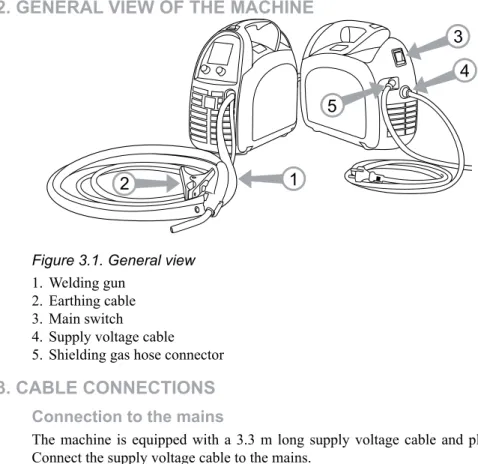
3.2. general VieW OF the Machine
Figure 3.1. General view 1. Welding gun
2. Earthing cable 3. Main switch
4. Supply voltage cable 5. Shielding gas hose connector
3.3. caBle cOnnectiOns
connection to the mains
The machine is equipped with a 3.3 m long supply voltage cable and plug. Connect the supply voltage cable to the mains.
NOTE! The fuse size needed is 16 A delayed.
If you use an extension cord, its cross-sectional area should be at least as large as the supply voltage cable’s (3 x 2.5 mm²). The maximum length for the extension cord is 50 m.
The machine can also be used with a generator. The minimum power for the generator is 4.2 kVA, and the recommended power 8.0 kVA in order for the machine to be used at maximum capacity.
earthing
The earthing cable is already connected to the machine. Clean the workpiece surface and fix the earthing cable clamp to the piece in order to create a closed and interference-free circuit needed for welding.
Welding gun
The welding gun is already connected to the machine. The welding gun leads the filler wire, shielding gas and electric current to the weld. When you press the welding gun trigger, shielding gas flow and wire feed begin. The arc ignites, when the filler wire touches the welded piece.
The factory-installed wire guide in the welding gun is best suited for steel wire welding. However, it can temporarily be used for stainless steel wire and aluminium wire welding. Then, however, friction is greater and thus the wire feed may tangle. If you mainly use stainless steel or aluminium wire, we recommend you change the wire guide to a plastic wire guide.
The gun neck can be rotated 360°. When turning the neck, always make sure that the neck is twisted almost all the way to the bottom. This prevents damaging and overheating the neck.
NOTE! If you use other than 0.8 mm diameter filler wire, change the
welding gun contact tip to match the wire thickness.
shielding gas
The shielding gas used for steel wires is carbon dioxide or a mixture of argon and carbon dioxide which replaces air in the arc’s area. Shielding gas for stainless steel wires is a mixture of argon and carbon dioxide (2%) and argon for aluminium wires. Thickness of the welded sheet and welding power define the flow rate of the shielding gas.
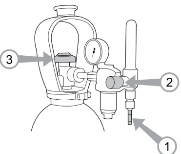
The machine is delivered with a 4.5 m long shielding gas hose. Connect the bayonet socket of the shielding gas hose to the machine’s hose connector and the hose connector end to the gas bottle’s control valve.
Figure 3.2. Connecting the gas hose to a typical control valve 1. Connect the hose to the gas bottle’s control valve and tighten the
connector.
2. Adjust the flow rate with the control valve screw. A suitable shielding gas flow rate is 8-15 l/min.
3. Close the bottle’s valve after use.
NOTE! Use a shielding gas suitable for the material’s welding. Fix the gas
bottle securely in an upright position before installing the control valve.
3.4. Filler Wire
The machine is delivered with the welding gun connected to +pole making it suitable for steel solid wire, stainless steel wire and aluminium wire welding without adjustments.
3.4.1. changing the feed roll groove
The feed roll groove is factory set for welding filler wires of 0.8-1.0 mm diameter. The feed roll groove must be changed if you use 0.6 mm thick filler wire.
Figure 3.3. Changing the feed roll groove 1. Open the feed roll from the pressure control lever. 2. Switch the machine on from the main switch.
3. Press the welding gun trigger and drive the feed roll in such a position that its locking screw is up and can be opened.
4. Switch the power off from the main switch.
5. Open the feed roll locking screw with a 2.0 mm Allen wrench approximately half a turn.
6. Pull the feed roll from its shaft.
7. Turn the feed roll and reinstall it to its shaft all the way to the bottom making sure that the screw is on the shaft’s level.
8. Tighten the feed roll locking screw.
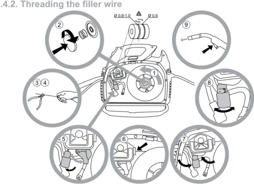
3.4.2. Threading the filler wire
Figure 3.4. Threading the filler wire
1. Open the reel housing by pressing on the opening button and install the wire reel in such a way that it rotates counter clockwise. You can use either a 5 kg (diameter 200 mm) or 1 kg (100 mm) wire reel in the machine. 2. Attach the reel with a reel lock.
3. Unfasten the wire end from the reel, but hold on to it all the time. 4. Straighten the wire end for approximately 20 cm and cut the wire in the
straightened location.
5. Open the pressure control lever which then opens the feed gear. 6. Thread the wire through the wire’s rear guide to the gun’s wire guide. 7. Close the feed gear and fasten it with the pressure control lever. Make sure
that the wire runs in the feed roll groove.
8. Adjust the compression pressure with the pressure control lever no higher than to the middle of the scale. If the pressure is too high, it removes metal fragments from the wire surface and may damage the wire. On the other hand, if the pressure is too low, the feed gear slips and the wire does not run smoothly.
9. Press the welding gun trigger and wait for the wire to come out. 10.Close the reel housing cover.
CAUTION! When driving the wire in to the gun, do not point the gun at yourself or others or put, for example, your hand in front of the tip, because the cut wire end is extremely sharp. Also, do not put your fingers near the feed rolls, because they might get squeezed between the rolls.
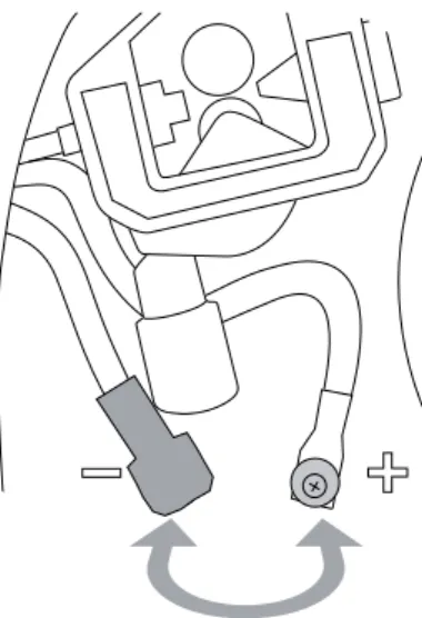
3.4.3. reversing polarity
Some filler wires are recommended to be welded with the gun in the –pole, so the polarity should be reversed. Check the recommended polarity from the filler wire package.
Figure 3.4. Reversing polarity
1. Disconnect the machine from the mains.
2. Bend the rubber cover of the earthing cable’s pole in such way that the cable can be disconnected.
3. Remove poles’ tightening nuts and washers. Note the correct order of the washers!
4. Interchange the cables.
5. Install the washers in place and close the tightening nuts to spanner tightness.
6. Put the rubber cover of the earthing cable’s pole firmly in place. The
3.5. cOntrOls anD inDicatOr lights
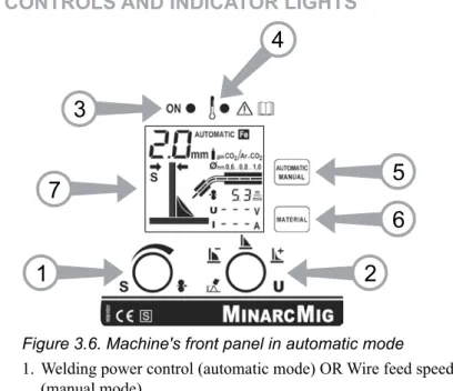
Figure 3.6. Machine's front panel in automatic mode
1. Welding power control (automatic mode) OR Wire feed speed control (manual mode)
2. Arc length trimmer (automatic mode) OR Welding voltage control (manual mode)
3. Standby indicator light 4. Overheating indicator light 5. Mode selection button
6. Material selection button (automatic mode) 7. Display
In automatic mode, the welding power is adjusted according to the thickness of the welded sheet. The machine also has a trimmer for arc length in automatic mode . There are three material options for filler wires and you can browse through them with the material selection button.
In manual mode, the wire feed speed and welding voltage are adjusted separately. Modes can be changed with the mode selection button. Note that material or sheet thickness selections made in the automatic mode are not valid in manual mode or manual mode’s selections in automatic mode.
Indicator lights display the machine’s standby mode and inform of a possible overheating.
�
�
�
�
�
�
�
When you switch the machine on, a green standby light switches on. Simultaneously, the main switch indicator light switches on. If the machine overheats or the supply voltage is too low or too high, the welding operation automatically switches off and the yellow overheating indicator light switches on. The light switches off when the machine is ready for operation again. Make sure that there is enough space around the machine allowing air to freely flow and cool the machine.
3.5.1. Display in automatic mode
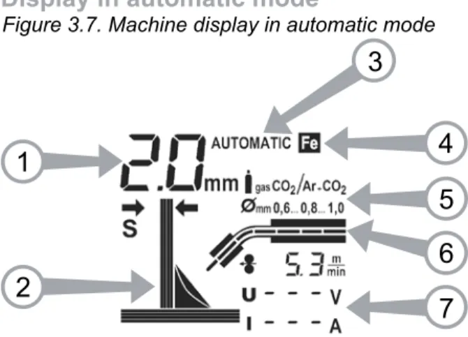
Figure 3.7. Machine display in automatic mode
1. Sheet thickness
2. Chart for sheet thickness and arc length trimmer 3. Operating mode
4. Material
5. Shielding gas and wire diameter recommendation 6. Wire feed speed chart
7. Welding values: wire feed speed, welding voltage and welding current Sheet thickness displays the selected welding power setting which is based on the fillet weld’s sheet thickness in millimetres. When you adjust the welding power according to sheet thickness, the sheet thickness in the chart changes thinner or thicker correspondingly.
The selected operating mode and material are shown on the display. The display also shows a recommendation as to what shielding gas and wire diameter should be used with the material in question.
During welding, the wire feed speed chart displays the wire’s speed.
Of all the welding parameters, only filler wire feed speed is visible on the display all the time. Welding voltage and welding current are visible on the display during welding. The last used values remain on the display until welding is restarted or settings are changed.
When adjusting the arc length, the voltage display shows a comparative scale (-9…0…9) which will disappear from the display after some time once the adjustment is made.
3.5.2. Welding power adjustment in automatic mode
Adjusting the welding power according to sheet thickness affects simultaneously both wire feed speed and amount of current lead to the wire. This is a good starting point for welding in different operating situations. However, connection type and root opening may influence the amount of welding power needed. Select the correct parameter with the welding power control according to the welded fillet weld’s sheet thickness. If the fillet weld’s sheets are of different thickness, use their average as a default parameter.
Sheet thickness display has been given in millimetres and it is based on , with steel and stainless steel wires, 0.8 mm wire diameter. When using a 0.6 mm wire, set the welding power control slightly higher than the used sheet thickness and correspondingly slightly lower with 0.9-1.0 mm wires. With aluminium wires, the welding power adjustment is based on 1.0 mm wire diameter.
NOTE! When welding for the first time, we recommend that you set the arc
length trimmer to 0.
3.5.3. arc length trimmer in automatic mode
The arc length trimmer adjusts the length of the arc shorter or longer and affects the welding temperature. A shorter arc is colder and a longer one hotter. The arc length trimmer also affects the arc’s welding properties and spatters with different combinations of filler wire diameters and shielding gases. The trimmer range is -9...0...9: negative values shorten and positive values lenghten the arc. The trimmer is preset at 0 which is, in most cases, a suitable basic setting. If the weld is too convex, the arc is too short or cold. Then adjust the arc longer or hotter by turning the control clockwise.
If, on the other hand, you want to weld with a colder arc to prevent for example the parent material from burning through, adjust the arc shorter by turning the control counter clockwise. You can also adjust the welding power, if need be. When adjusting the arc length, the weld on the arc trimmer chart on the display correspondingly changes more concave or convex.
Once the arc has been trimmed, it usually does not need to be changed when the welded sheet thickness changes.
3.5.4. Display in manual mode
Figure 3.8. Machine display in manual mode 1. Operating mode
2. Wire feed speed chart
3. Welding values: wire feed speed, welding voltage and welding current The selected operating mode is visible on the display. During welding, the wire feed speed chart displays the wire’s speed.
Wire feed speed is the only welding parameter always visible on the display. When adjusting welding voltage, the display shows the set value for the voltage, and only during welding does the display show the actual value. Welding current is visible on the display only during welding.
Values for actual welding voltage and welding current remain on the display after welding until welding is restarted or settings are changed.
3.5.5. Adjustments in manual mode
In manual mode, the wire feed speed and welding voltage are both adjusted separately. Welding current and power are defined according to wire feed speed. The desired arc and welding properties can be reached by adjusting the voltage.
3.6. threaDing the shOulDer strap
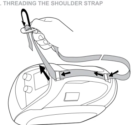
Figure 3.9. Threading the shoulder strap in place
The machine is delivered with a shoulder strap which helps carrying the machine. Thread the shoulder strap in place according to the picture.
NOTE! The machine should not be hung up from the shoulder strap.
4. serVice
When servicing the machine, its utilization degree and environmental circumstances should be taken into account. If you use the machine appropriately and service it regularly, you will spare yourself from unnecessary malfunctions.
CAUTION! Disconnect the machine from the mains before handling the electrical cables.
4.1. DailY Maintenance
• Remove welding spatters from the welding gun’s tip and check the condition of the parts. Change damaged parts to new ones immediately. Only use original Kemppi spare parts.
• Check that the insulating tips of the welding gun’s neck are undamaged and in place. Change damaged insulation parts to new ones immediately. • Check the tightness of the welding gun’s and earthing cable’s connections. • Check the condition of the supply voltage and welding cable and replace
faulty cables.
4.2. Maintenance OF the Wire FeeD MechanisM
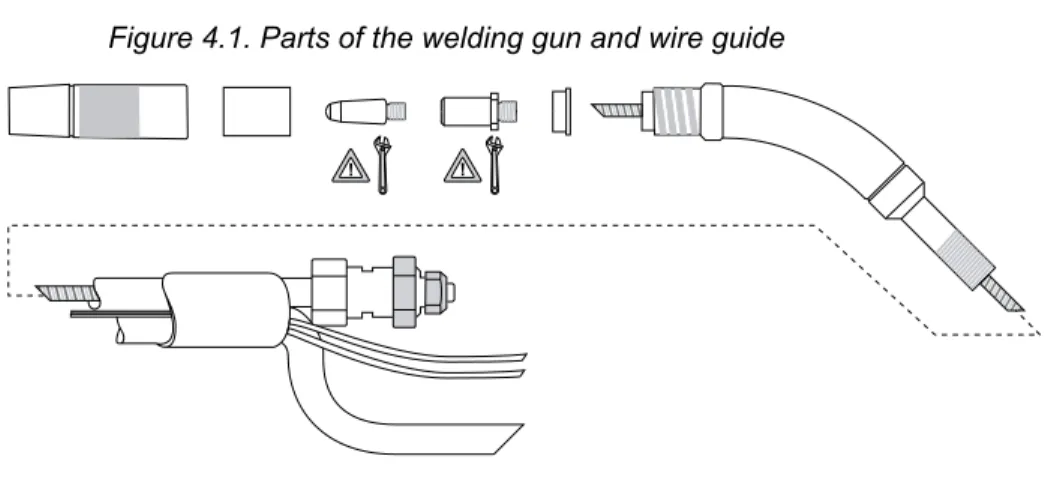
Figure 4.1. Parts of the welding gun and wire guideService the wire feed mechanism at least every time the reel is changed. • Check the wear of the feed roll groove and change the feed roll when
necessary.
• Clean the welding gun wire guide with compressed air.
Cleaning the wire guide
Pressure of the feed rolls remove metal dust from the filler wire’s surface which then finds its way to the wire guide. If the wire guide is not cleaned, it gradually clogs up and causes wire feed malfunctions. Clean the wire guide in the following manner:
1. Remove the welding gun’s gas nozzle, contact tip and contact tip’s adapter. 2. With a pneumatic pistol, blow compressed air through the wire guide. 3. Blow the wire feed mechanism and reel housing clean with compressed
air.
4. Reattach the welding gun’s parts. Tighten the contact tip and contact tip’s adapter to spanner tightness.
Changing the wire guide
If the wire guide is too worn or totally clogged, change it to a new one according to the following instructions. The wire guide should also be replaced with a plastic one, if you mainly use stailess steel or aluminium wire.
1. Disconnect the welding gun from the machine.
a. Disconnect the cable clamp of the gun’s power cable by opening the screws.
b. Disconnect the gun’s power cable from the machine’s pole.
c. Disconnect the connector of the trigger conductors from the machine. d. Open the gun’s mounting nut.
e. Extract the gun gently from the machine whereupon all parts come through the front part’s cable hole.
2. Open the mounting nut of the wire guide which exposes the end of the wire guide.
3. Straighten the welding gun’s cable and withdraw the wire guide from the gun.
4. Push a new wire guide in to the gun. Make sure that the wire guide enters all the way into the contact tip’s adapter and that there is an o-ring at the machine-end of the guide.
5. Tighten the wire guide in place with the mounting nut.
6. Cut the wire guide 2 mm from the mounting nut and file the sharp edges of the cut round.
7. Reattach the gun in place and tighten the parts to spanner tightness.
4.3. Machine DispOsal
Do not dispose of electrical equipment together with normal waste!
In observance of European Directive 2002/96/EC on Waste Electrical and Electronic Equipment and its implementation in accordance with national law, electrical equipment that has reached the end of its life must be collected separately and returned to an environmentally compatible recycling facility. As the owner of the equipment, you should get information on approved collection systems from our local representative.
By applying this European Directive you will improve the environment and human health.
prODuct OrDering nuMBer MinarcMig™ Adaptive 180
(includung gun, cables, gas hose and shoulder strap)
6108180
Welding gun MMG20 (3 m) 6250200
Earthing cable and clamp (3 m) 6184003 Shielding gas hose (4,5 m) W001077
Shoulder strap 9592162
Consumables for wire feed mechanism
Feed roll 0,6-1,0 mm W000749
Feed roll 0,8-1,0 mm, knurled W001692
Pressure roll 9510112
Wire rear guide W000651
Parts for wire reel hub
Reel flange W000728
Spring W000980
Wire reel lock W000727
Consumables for MMG20 gun
Gas nozzle 9580101
Gas nozzle insulating bush 9591010
Contact tip M6 ø 0,6 mm 9876634
Contact tip M6 ø 0,8 mm 9876635
Contact tip M6 ø 0,9 mm 9876633
Contact tip M6 ø 1,0 mm 9876636
Contact tip adapter 9580173
Neck insulating ring 9591079
Wire guide 0,6-1,0 mm (Fe) 4307650 Wire guide 0,6-1,0 mm (Ss, Al) 4307660
4.4. OrDering nuMBers
5. trOuBleshOOting
prOBleM cause
The wire does not move or wire feed entangles
Feed rolls, wire conduit or contact tips are defective • Check that feed rolls are not too tight or too loose • Check that the feed roll groove is not too worn • Check that the wire conduit is not blocked
• Check that the contact tip and wire guide are suitable for the wire used
• Check that there are no spatters on the conduit tip and that the hole is not cramped or worn loosei Main switch
indicator does not switch on
The machine has no supply voltage light • Check supply voltage fuses
• Check supply voltage cable and plug Machine welds
badly Welding outcome is influenced by several factors • Check that the wire feed is constant • Check the trimming settings of welding power
control and arc length
• Check the material selection setting
• Check that the earthing clamp is fixed properly, fixing point is clean, and both cable and its connections are undamaged
• Check that the shielding gas is suitable for the wire material used
• Check the flow of shielding gas from the tip of the welding gun
• Supply voltage is uneven, too low or too high Over-heating
indicator light switches on
The machine has over-heated
• Check that cooling air can flow without obstructions • Machine’s volume-capacity ratio has been exceeded;
wait for the indicator light to switch off • The supply voltage is too low or too high
If the machine’s malfunction can not be corrected with these measures, contact the KEMPPI maintenance service.
6. technical Data
The machine complies with the CE mark standards. MinarcMig™ aDaptiVe 180 Connection voltage 1 ~ 230 V ±15%, 50/60 Hz Connection power: • 25% ED 8,6 kVA 180 A • 60% ED 5,3 kVA 120A • 100% ED 4,2 kVA 100A
Connection cable/fuse 2,5 mm² S–3,3 m / 16 A delayed Load capacity:
• 25% ED 180 A / 23,0 V
• 60% ED 120 A / 20,0 V
• 100% ED 100 A / 19,0 V
Adjustment range 20-180 A / 12-23 V Wire feed adjustment range 1-12 m/min
Open-circuit voltage 15,5- 42,5 V Power ratio 0,60 (180 A / 23,0 V) Operating efficiency 0,81 (180 A / 23,0 V) Filler wires: • Fe solid wire ø 0,6...1,0 mm • Fe cored wire ø 0,8...1,0 mm • Ss ø 0,8...1,0 mm • Al ø 1,0 mm
Shielding gases CO², Ar, Ar+CO² -mixed Maximum size of the wire reel ø 200 mm / 5 kg Temperature class H (180°C) / F (155°C)
Dimensions L 400 x W 180 x H 340 mm
Weight (incl. gun and cables 3,0 kg) 9,8 kg Operating temperature range -20°C...+40°C Storage temperature range -40°C...+60°C
Protection class IP23C
7. terMs OF guarantee
Kemppi Oy provides a guarantee for products manufactured and sold by them if defects in manufacture and materials occur. Guarantee repairs must be carried out only by an Authorised Kemppi Service Agent. Packing, freight and insurance costs to be paid by orderer.
The guarantee is effected on the date of purchase. Verbal promises which do not comply with the terms of guarantee are not binding on guarantor.
limitations on guarantee
The following conditions are not covered under the terms of guarantee: defects due to natural wear and tear, non-compliance with operating and maintenance instructions, connection to incorrect or faulty supply voltage (including voltage surges outside equipment spec.), incorrect gas pressure, overloading, transport or storage damage, fire or damage due to natural causes i.e. lightning or flooding. This guarantee does not cover direct or indirect travelling costs, daily allowances or accommodation.
Under the terms of guarantee, welding torches and their consumables, feeder drive rolls and feeder guide tubes are not covered.
Direct or indirect damage due to a defective product is not covered under the guarantee.
The guarantee is void if changes are made to the product without approval of the manufacturer, or if repairs are carried out using non-approved spare parts. The guarantee is also void if repairs are carried out by non-authorised agents. undertaking guarantee repairs
Guarantee defects must be informed to Kemppi or authorised Kemppi Service Agents within the guarantee period.
Before any guarantee work is undertaken, the customer must provide proof of guarantee or proof of purchase , and serial number of the equipment in order to validate the guarantee. The parts replaced under the terns of guarantee remain the property of Kemppi.
Following the guarantee repair, the guarantee of the machine or equipment, repaired or replaced, will be continued to the end of the original guarantee period.
DK – 2740 SKOVLUNDE DANMARK
Tel 44 941 677 Telefax 44 941 536 e-mail: [email protected]
KEMPPI FRANCE S.A.S 65 Avenue de la Couronne des Prés 78681 EPONE CEDEX FRANCE Tel (01) 30 90 04 40 Telefax (01) 30 90 04 45 e-mail: [email protected] FIN – 15801 LAHTI FINLAND Tel (03) 0899 11 Telefax (03) 899 428 www.kemppi.com KEMPPIKONEET OY PL 13 FIN – 15801 LAHTI FINLAND Tel (03) 899 11 Telefax (03) 7348 398 e-mail: myynti.fi@kemppi.com KEMPPI SVERIGE AB Box 717 S – 194 27 UPPLANDS VÄSBY SVERIGE Tel (08) 59 078 300 Telefax (08) 59 082 394 e-mail: [email protected] KEMPPI NORGE A/S Postboks 2151, Postterminalen N – 3103 TØNSBERG NORGE Tel 33 34 60 00 Telefax 33 34 60 10 e-mail: [email protected] KEMPPI BENELUX B.V. Postbus 5603 NL – 4801 EA BREDA NEDERLAND Tel (076) 5717 750 Telefax (076) 5716 345 e-mail: [email protected] KEMPPI (UK) Ltd
Martti Kemppi Building Fraser Road Priory Business Park BEDFORD, MK443WH ENGLAND Tel 0845 6444201 Fax 0845 6444202 e-mail: [email protected] D – 35510 BUTZBACH DEUTSCHLAND Tel (06033) 88 020 Telefax (06033) 72 528 e-mail: [email protected]
KEMPPI AUSTRALIA PTY LTD. 25A Stennett Road, Ingleburn NSW 2565, AUSTRALIA Tel +61-2-9605 9500 Telefax +61-2-9605 5999 e-mail: [email protected] KEMPPI SP. z o.o. UI. Piłsudskiego 2 05-091 ZABKI POLAND Tel +48 22 781 6162 Telefax +48 22 781 6505 e-mail: [email protected]
www.kemppi.com
OOO KEMPPI127018 Moscow, Polkovaya str. 1, Building 6 ООО Кемппи
127018 Москва, ул. Полковая 1, строение 6 e-mail: [email protected]