RNS
®
System User Manual
ii
This Manual supports:
•
RNS
®Neurostimulator: model RNS-300M with firmware version 7.0
•
NeuroPace
®Cortical Strip Lead: models CL-315-10, CL-325-10, CL-335-10
•
NeuroPace
®Depth Lead: models DL-330-3.5, DL-330-10, DL-344-3.5,
DL-344-10
•
NeuroPace
®Programmer: model PGM-300 with software version 1.6
FCC Information
The following is communications regulation information on the model RNS-300M
neurostimulator and model W-02 wand.
Neurostimulator FCC ID: WBWRF300
Wand FCC ID:
WBW902
This device complies with Part 15 of the FCC Rules. Operation is subject to the
following two conditions: (1) This device may not cause harmful interference, and (2)
this device must accept any interference received, including interference that may
cause undesired operation.
IMPORTANT:
Changes or modifications to this product not expressly approved by
NeuroPace, Inc. could void the FCC Certification, and negate your authority to operate
them.
This equipment complies with FCC radiation exposure limits set forth for an uncontrolled
environment. This transmitter must not be co-located or operating in conjunction with
any other antenna or transmitter.
1
TABLE OF CONTENTS
INTRODUCTION ... 5
CONTACTING NEUROPACE ... 5
ABOUT THIS MANUAL ... 5
RNS® SYSTEM ... 9
INDICATIONS ... 9
CONTRAINDICATIONS ... 9
WARNINGS AND PRECAUTIONS ... 10
IMPLANTED RNS®SYSTEM ... 19
RNS®SYSTEM DESCRIPTION ... 19
RNS®NEUROSTIMULATOR ... 22
RNS®SYSTEM COMPONENTS AND ACCESSORIES ... 22
NEUROPACE®CORTICAL STRIP LEAD ... 23
NEUROPACE®DEPTH LEAD ... 23
LEAD COMPONENT AND ACCESSORIES ... 24
NEUROPACE®PROGRAMMER ... 24
TELEMETRY WAND ... 25
NEUROPACE®PATIENT DATA MANAGEMENT SYSTEM ... 25
STERILIZATION,STORAGE, AND HANDLING ... 26
RNS®SYSTEM LONGEVITY ... 27
PRODUCT REGISTRATION ... 28
CLINICAL USE OF THE RNS® SYSTEM ... 29
IDENTIFYING CANDIDATES FOR THE RNS®SYSTEM THERAPY ... 29
LOCALIZING THE SEIZURE FOCUS AND PLANNING LEAD LOCATION ... 29
PATIENT TRAINING ... 30
OVERVIEW OF IMPLANTATION AND PROGRAMMING OF THE RNS®SYSTEM ... 30
Implanting the RNS® Neurostimulator and Leads ... 30
Recommended Initial Detection and ECoG Storage Settings ... 30
Recommended Initial Responsive Therapy Settings ... 31
Modifying Detection and Responsive Therapy Settings... 32
SURGICAL PROCEDURES ... 33
PRE-IMPLANT ... 33
RECOMMENDED IMPLANT PROCEDURE FLOW CHART ... 35
RECOMMENDED NEUROPACE®DEPTH LEAD IMPLANTATION AND FIXATION ... 36
RECOMMENDED NEUROPACE®CORTICAL STRIP LEAD IMPLANTATION AND FIXATION ... 39
RECOMMENDED RNS®NEUROSTIMULATOR IMPLANTATION PROCEDURE ... 40
CONNECTING THE RNS®NEUROSTIMULATOR TO THE IMPLANTED LEAD(S) ... 44
REPLACING /EXPLANTING THE RNS®SYSTEM ... 48
CHANGING THE LEADS THAT ARE CONNECTED TO THE NEUROSTIMULATOR ... 51
PROGRAMMING INSTRUCTIONS ... 54
LOGGING ONTO THE NEUROPACE®PROGRAMMER ... 54
TESTING THE WAND SIGNAL ... 54
INTERROGATING THE RNS®NEUROSTIMULATOR ... 54
IMPEDANCE MEASUREMENTS ... 55
BATTERY VOLTAGE MEASUREMENTS ... 55
CAPTURING REAL-TIME ECOGS ... 55
OBTAINING NEUROSTIMULATOR ACTIVITY INFORMATION ... 56
REVIEWING ECOGRECORDS RETRIEVED FROM THE RNS®NEUROSTIMULATOR ... 56
DELIVERING TEST STIMULATIONS ... 57
SYNCHRONIZING THE PROGRAMMER WITH THE NEUROPACE®PATIENT DATA MANAGEMENT SYSTEM ... 58
2
Entering Patient Information into the Programmer ... 59
Entering Physician Emergency Contact Information ... 59
Programming Information ... 59
ASSIGNING LEAD LABELS AND CREATING THE MONTAGE ... 59
Assigning the Lead Labels ... 59
Recommended Initial Lead Labels ... 61
Creating a Montage ... 62
Recommended Initial Montage settings ... 62
Programming the Newly selected Settings ... 63
SETTING UP ECOGSTORAGE ... 63
Selecting ECoG Storage Settings ... 63
Recommended Initial ECoG Storage Settings ... 64
Recommended Modifications to ECoG Storage Settings ... 66
Programming the Newly Selected ECoGs Storage Settings... 67
SETTING UP DETECTION ... 68
Enabling, Disabling, or Changing the Detection Settings ... 68
Recommended Initial Detection Settings ... 69
Recommended Modifications to Detection Settings ... 69
Programming the Newly Selected Detection Settings ... 73
SETTING UP RESPONSIVE THERAPY ... 74
Enabling, Disabling, or Changing Responsive Therapy ... 75
Recommended Initial Responsive Therapy Settings ... 76
Recommended Modifications to Responsive Therapy Settings ... 79
Programming the Newly Selected Settings ... 79
REVIEWING REPORTS ... 80
MAGNET ... 81
PATIENT FOLLOW-UP ACTIVITIES ... 82
TROUBLESHOOTING ... 83
DAMAGED PRODUCTS ... 83
GENERAL TROUBLESHOOTING ACTIVITIES ... 83
Abnormal Lead Impedance (greater than 3500 Ohms or less than 250 Ohms) ... 83
Noise, Artifacts, Poor Signal Displayed, or No Signal Displayed in Real-time ECoG ... 85
Poor or No Communication Between the RNS® Neurostimulator and the Programmer ... 86
Programmer Turns OFF or Freezes ... 86
Low Battery Measurement ... 87
Impedance Measurement was Rejected / Test Request was Rejected ... 87
RNS® Neurostimulator Reset (DC Leak Detected) ... 87
SPECIFICATIONS ... 89
RNS®NEUROSTIMULATOR SPECIFICATIONS ... 89
RNS®SYSTEM WIRELESS SPECIFICATIONS ... 90
RNS®SYSTEM LEAD SPECIFICATIONS ... 90
RNS®SYSTEM LEAD SPECIFICATIONS ... 90
IMPLANTABLE RNS®SYSTEM COMPONENTS AND ACCESSORIES ... 91
NEUROPACE®PROGRAMMER ... 91
ELECTROMAGNETIC EMISSIONS AND IMMUNITY ... 92
SYSTEM PRODUCTS, COMPONENTS, ACCESSORIES, AND TOOLS ... 97
GLOSSARY ... 100
3
Explanation of symbols on product or package labeling
Refer to the appropriate product for symbols that apply.
Caution
Do Not Resterilize
MR Unsafe
Prescription Only
Pyrogen Free
Single Use
Sterilized Using Ethylene Oxide
Temperature Limits
Ethernet Connection (Network Connection)
Proposition 65, a State of California voter initiative, requires the following notice:
WARNING: Some product components may expose you to chemicals known to the State of California to cause cancer, or birth defects, or other reproductive harm.
Introduction
5
I
NTRODUCTION
CONTACTING NEUROPACE
All questions or concerns regarding the NeuroPace® RNS® System should be forwarded to: NeuroPace, Inc.
455 N. Bernardo Ave. Mountain View, CA 94043
Customer Support: 1-866-726-3876 (Toll Free in the United States) Fax: 650-237-2855
Website: www.NeuroPace.com
ABOUT THIS MANUAL
This manual is intended to provide guidelines for implanting the RNS® System, including the
NeuroPace® RNS® Neurostimulator, NeuroPace® Cortical Strip Leads and NeuroPace® Depth Leads, and instructions for using the NeuroPace® Programmer.
Manual Contents
• Introduction - Overview of the typographical conventions and contents of the manual • RNS® System Description - Indications, contraindications, product descriptions, theory of
system operation, warnings, and precautions
• Clinical Use of the RNS® System - Physician and center access, identifying candidates, pre-surgical planning, patient training, overview of implantation and initial programming recommendations
• Surgical Procedures - Instructions for implanting the RNS® System
• Instructions for Use - Description of the settings available in the neurostimulator and instructions for programming, instructions for individualizing patient detection settings, instructions for individualizing patient therapy settings
• Patient Follow-Up - Guidelines for follow-up appointments, follow-up activities, and patient counseling
• Troubleshooting - Information that may be helpful in solving problems encountered while implanting or operating the RNS® System
• Specifications - List of each product with its mechanical and electrical characteristics • Glossary - Alphabetical list of terms used in the manual with their definitions
Introduction
6
Typographic Conventions
This manual uses different formats and symbols to distinguish instructions, warnings, precautions, notes, lists, and figures.
WARNING: WARNING TITLE
Warnings alert the user to serious adverse events and potential safety hazards and situations that may cause injury.
Precaution: PRECAUTION TITLE
Precautions alert the user to exercise special care in the safe and effective use of the RNS® System.
Note: Notes provide additional information that is particularly useful or important.
1. Numbered paragraphs contain instructions that provide explanations and/or procedural information.
• Bullet points indicate items in a list.
Figure: Statements regarding a figure are located below the figure between double lines such as this.
Bold italicized text refers the user to a specific location in this manual for further details.
BOLD SMALL CAPS assist the user in navigating to the appropriate tab or button on the NeuroPace® Programmer screen.
Introduction
7
The tabs are displayed on the NeuroPace® Programmer screen as follows:
Page Tab
Responsive Neurostimulator System
9
RNS
®S
YSTEM
INDICATIONS
The RNS® System is an adjunctive therapy in reducing the frequency of seizures in individuals 18 years of age or older with partial onset seizures who have undergone diagnostic testing that localized no more than 2 epileptogenic foci, are refractory to two or more antiepileptic medications, and currently have frequent and disabling seizures (motor partial seizures, complex partial seizures and / or secondarily generalized seizures). The RNS® System has demonstrated safety and effectiveness in patients who average 3 or more disabling seizures per month over the three most recent months (with no month with fewer than two seizures), and has not been evaluated in patients with less frequent seizures.
CONTRAINDICATIONS
The RNS® System is contraindicated for:
• Patients at high risk for surgical complications such as active systemic infection, coagulation disorders (such as the use of anti-thrombotic therapies) or platelet count below 50,000. • Patients who have medical devices implanted that deliver electrical energy to the brain. • Patients who are unable, or do not have the necessary assistance, to properly operate the
NeuroPace® Remote Monitor or magnet.
The following medical procedures are contraindicated for patients with an implanted RNS® System. Energy from these procedures can be sent through the implanted brain stimulation system and cause permanent brain damage which may cause severe injury, coma, or death. Brain damage can occur from any of the listed procedures even if the RNS® Neurostimulator is turned off or if the leads are not connected to the neurostimulator, and can occur even if the neurostimulator has been removed and any leads (or any part of a lead) or the cranial prosthesis remain.
• MR imaging is contraindicated for patients with an implanted RNS® System. Do not perform an MRI on a patient with any implanted RNS® Neurostimulator or lead (or any portion of a lead). Even if the neurostimulator has been removed, you should not have an MRI if any part of a lead or the cranial prosthesis is still implanted.
The RNS® System is MR Unsafe. Testing has not been performed to define conditions of use to ensure safety of the RNS® System in an MR environment.
• Diathermy procedures are contraindicated in patients implanted with an RNS® Neurostimulator and associated leads. (Diathermy is any treatment that uses high-frequency electromagnetic radiation, electric currents, or ultrasonic waves to produce heat in body tissues.) Patients
absolutely CANNOT be treated with any type of shortwave, microwave, or therapeutic ultrasound diathermy device whether or not it is used to produce heat. These treatments should not be applied anywhere on the body.
• Electroconvulsive Therapy (ECT) is contraindicated for patients with an implanted RNS® System. • Transcranial Magnetic Stimulation (TMS) is contraindicated for patients with an implanted RNS®
Responsive Neurostimulator System
10
WARNINGS AND PRECAUTIONS
WARNINGS -CLINICAL USE
WARNING: PHYSICIAN AND CENTER ACCESS TO THE RNS®SYSTEM
The RNS® System should only be implanted by neurosurgeons with adequate experience in the implantation of subdural and stereotactic implantation of
intraparenchymal electrodes and in the surgical treatment of intractable epilepsy. The RNS® System should only be used by neurologists or neurosurgeons with adequate experience in the management of intractable epilepsy and in the localization of epileptic foci, including the use of scalp and intracranial electrodes.
Neurologists and neurosurgeons using the RNS® System must have completed the NeuroPace® RNS® System training program. To qualify to manage patients with the RNS® System, physicians must demonstrate specific expertise related to epilepsy, video-EEG monitoring, interpretation of electrocorticograms (ECoGs), the
pharmacology of antiepileptic medications and selection of patients for epilepsy surgery. Implantation of the RNS® System should be performed only by qualified neurosurgeons at centers capable of providing comprehensive epilepsy care, i.e. “Comprehensive Epilepsy Centers”. These centers should have the expertise to provide diagnostic services that include video-EEG monitoring with scalp and
intracranial electrodes and neuroimaging, and are experts in the treatment of epilepsy with antiepileptic medications, epilepsy surgery and devices.
WARNING: MANAGEMENT OF PATIENTS WITH THE RNS®SYSTEM BY PHYSICIANS AT CENTERS THAT DO NOT PROVIDE THE SERVICES PROVIDED AT COMPREHENSIVE EPILEPSY CENTERS
In some instances, post-implant programming may be conducted by neurologists meeting the experience and certification requirements for neurologists at
Comprehensive Epilepsy Centers, but who are not practicing in such centers. This situation might occur if the patient is not able to travel to a Comprehensive Epilepsy Center for regular follow-up (e.g. because of distance from the Center or limited access to transportation). These neurologists will be qualified by NeuroPace to provide post-implant programming. After NeuroPace® RNS® System training is complete, the qualified programming neurologist may receive external NeuroPace products
(programmer, remote monitor).
WARNINGS –SURGICAL
WARNING: COMPATIBILITY WITH SIMILAR IMPLANTABLE PRODUCTS
The NeuroPace® RNS® Neurostimulator, NeuroPace® Cortical Strip Lead, and NeuroPace® Depth Lead are not compatible with non-NeuroPace leads and/or pulse generators. Incompatible configurations may cause damage to the products and may result in unsafe current densities delivered to the patient.
WARNING: CORTICAL STRIP LEAD EXPLANTATION
Explanting a chronically implanted cortical strip lead may cause tissue damage.
WARNING: INFECTION
Infection, including bacterial meningitis, may occur as a result of the RNS® System implant procedures and/or the RNS® System materials. Standard surgical infection prevention measures (antibiotics etc.) should be taken both pre- and post-implantation.
Responsive Neurostimulator System
11
WARNING: INTRACRANIAL HEMORRHAGE
Intracranial hemorrhage may occur when implanting the RNS® System. Placing the leads, ferrule, and/or neurostimulator in an area where excess pressure may occur to the underlying blood vessels may cause intracranial hemorrhage. Patients with underlying risk factors for intracranial hemorrhage, such as patients with previous head trauma, anticoagulant use, or who experience head injury with seizures should be taken into specific consideration.
WARNING: SURGICAL PROCEDURE SIDE EFFECTS
Surgical procedure risks may include, but are not limited to, temporary pain at the implant site, CSF leakage and although rare, epidural hemorrhage, seroma, subdural or epidural hematoma and paralysis.
WARNINGS –RNS®SYSTEM AND THERAPY
WARNING: ADVERSE TISSUE REACTION
Allergic reaction to the RNS® System materials and/or leads implanted is possible.
WARNING: CHRONIC TISSUE STIMULATION
The effects of long-term brain stimulation are not completely known and may present some risks to the patient.
WARNING: EROSION
Skin erosion may occur on and/or around the neurostimulator and/or lead implant site, particularly in the case of protrusion of the implanted RNS® System products above the surface of the skull.
WARNING: LEAD MIGRATION
The implanted lead(s) may migrate from their desired implant location. Lead migration can result in changes in detections and stimulation effectiveness, and may require additional surgical procedures to modify the lead location.
WARNING: PREGNANT WOMEN
The safety and effectiveness of the RNS® System has not been studied in pregnant women.
WARNING: RNS®SYSTEM FAILURE
As with any electronic device, the RNS® System may malfunction (not work). Potential causes include battery malfunctions, an electrical short, open circuits, lead fractures, lead insulation failures, or damage as a result of head trauma. These malfunctions are unpredictable, and may result in too little stimulation or no stimulation. A lead failure may result in the lead needing to be removed or repositioned, which would require surgery. A malfunctioning neurostimulator may need to be replaced, which would require surgery. Although the neurostimulator is designed to turn off if overstimulation or excess current occurs, there is a possibility that product failure could result in brain tissue damage.
WARNING: PATIENT DATA COLLECTION
The patient must be willing to collect data daily from their neurostimulator and send the data to the PDMS database at least once a week.
Responsive Neurostimulator System
12
WARNING: CASE DAMAGE
If the neurostimulator case is ruptured or pierced due to outside forces, severe brain tissue damage could result from exposure to the battery chemicals.
WARNING: ELECTROMAGNETIC INTERFERENCE (EMI)
Electromagnetic interference is a field of energy generated by equipment found in the home, work, medical, or public environments that is strong enough to interfere with neurostimulator function. Sources of strong electromagnetic interference can result in the following effects:
• Serious patient injury or death - It is possible for the interference sources to couple enough energy into a neurostimulator system to damage brain tissue
• System damage - resulting in a loss or change in symptom control and requiring reoperation
• Operational changes to the neurostimulator - causing stimulation to turn on or off, or resetting or reprogramming the neurostimulator resulting in a return of symptoms
• Unexpected changes in stimulation - causing a momentary increase in stimulation which may be felt by the patient
Patients should exercise caution in avoidance of devices which generate a strong electric or magnetic field. Refer to Electromagnetic Emissions and Immunity for more information.
WARNING: RADIO FREQUENCY IDENTIFICATION (RFID)INTERFERENCE
Sources of RFID can result in signals that appear as ECoG activity to the
neurostimulator. Signals that appear as ECoG activity could also result in delivering the programmed stimulation to the patient (per the device detection programming). The physician should be aware of possible sensing artifacts when assessing the ECoG recordings. Potential sources of RFID may occur in a health care environment, retail stores, public libraries, airports and business environments.
Refer to Electromagnetic Emissions and Immunity for more information.
WARNING: SECURITY AND ELECTRONIC TRACKING SYSTEMS
Security screening devices (such as theft detectors and airport security screening devices) can result in signals that appear as ECoG activity to the neurostimulator. Signals that appear as ECoG activity could also result in delivering the programmed stimulation to the patient (per the device detection programming). Such devices may be found at retail stores, public libraries and airports. The physician should be aware of possible sensing artifacts when assessing the ECoG recordings. Patients should be instructed to walk through the center of such security screening units without stopping, when possible, and exit the area of the screening device as soon as possible.
Responsive Neurostimulator System
13
WARNING: INTERACTION WITH IMPLANTED CARDIAC DEVICES
Possible effects of implanted device interaction with an implanted cardiac device (e.g., pacemaker or defibrillator) include the following:
• Defibrillation therapy from an implanted defibrillator may damage the device.
• The electrical pulses from the neurostimulation system may interact with the sensing operation from a cardiac device and could result in an inappropriate response of the cardiac device and vice versa.
WARNINGS –PROGRAMMER
WARNING: POTENTIAL SHOCK
Submerging any part of the programmer, or operating the programmer in or near a wet environment, may result in an electrical shock.
The programmer must be disconnected from the electrical outlet prior to cleaning to avoid the potential of electrical shock.
Electrical shock may occur if the programmer AC adapter and power cord are not properly connected to a grounded power source.
WARNINGS –MEDICAL ENVIRONMENT
WARNING: LITHOTRIPSY
The effects of extracoporeal shock wave lithotripsy on the RNS® System have not been studied. Exposure to high-output ultrasonic frequencies may damage the RNS® System. This could result in loss of therapy, and additional surgery to remove or replace components of the RNS® System. Prior to any administration of lithotripsy, the administering physician should consult with the physician prescribing the RNS® System.
WARNING: RADIATION
The effects of high radiation sources (such as cobalt 60 or gamma radiation used in cancer therapy) on the RNS® System have not been studied. Exposure to high levels of radiation may damage the RNS® System. This could result in loss of therapy, and additional surgery to remove or replace components of the RNS® System. Prior to any course of radiation therapy, the radiation oncologist should consult with the physician prescribing the RNS® System.
WARNING: ELECTROLYSIS
The effects of electrolysis on the RNS® System have not been studied. Electrolysis on the head or neck should be avoided.
Responsive Neurostimulator System
14
WARNING: COMPUTERIZED TOMOGRAPHY (CT)SCANS
For CT procedures on a patient with an implanted RNS® Neurostimulator, the operator should:
• Ask the patient to have the neurostimulator temporarily shut off with a programmer while the scan is performed, if possible.
• Minimize x-ray exposure to the implanted electronic medical device by:
• Using the lowest possible x-ray tube current consistent with obtaining the required image quality.
• Making sure that the x-ray beam does not dwell over the device for more than a few seconds.
Important note: For CT procedures that require scanning over the medical device continuously for more than a few seconds, as with CT perfusion or interventional exams, attending staff should be ready to take emergency measures to treat adverse reactions if they occur.
After CT scanning, the operator should:
• Ask the patient to have the neurostimulator turned back on with a programmer if it had been turned off prior to scanning.
• Advise the patient to contact their healthcare provider as soon as possible if they have questions or suspect their device is not functioning properly after any medical procedure.
Responsive Neurostimulator System
15
PRECAUTIONS –SURGICAL
Precaution: Connector Plug
A vacant port in the connector cover must be filled with a connector plug (provided in the connector cover kit). There is an increased risk of neurostimulator failure if a connector cover port is vacant.
Precaution: Epidural Lead Placement
Leads placed epidurally may cause pain during electrical stimulation.
Precaution: Lead Damage
Bending, kinking, and stretching of the lead may cause lead damage. Handle the lead with care.
Precaution: Sub-galeal Lead Placement
Wrapping the lead(s) on/around the neurostimulator or placing excess lead near the neurostimulator may result in lead damage during subsequent surgical procedures.
Precaution: Suture Sleeves
Suture sleeves are provided for use if sutures are used to stabilize the lead. Suturing directly on the lead may cause lead body damage and malfunction.
PRECAUTIONS –RNS®SYSTEM AND THERAPY
Precaution: Afterdischarge Activity
If evidence of afterdischarge activity resulting from stimulation is seen either on stored ECoGs or during test stimulation delivery, stimulation parameters should be adjusted to prevent such occurrence.
Precaution: Battery Depletion
For continued operation, the RNS® Neurostimulator needs to be surgically replaced when the battery is depleted.
Precaution: Neurostimulator Longevity
High and frequent levels of stimulation reduce neurostimulator battery longevity.
Precaution: Draining the Neurostimulator Battery
Testing the wand placement over the RNS® Neurostimulator for more than 10 minutes per day may drain the neurostimulator battery prematurely.
Precaution: Frequency of Remote Monitoring
The patient shouldinterrogate the RNS® Neurostimulator with the remote monitor and wand daily and synchronize the remote monitor with the PDMS at least once a week.
Responsive Neurostimulator System
16
Precaution: Explantation and EMI Considerations
If any system components (neurostimulator, leads, lead fragments, or cranial
prosthesis) remain implanted in the patient after a partial system explant, the patient is still susceptible to possible adverse effects from strong sources of EMI. It is possible for the interference sources to couple enough energy into a neurostimulator system to damage brain tissue, resulting in serious patient injury or death.Patients who have system components implanted should exercise caution in avoidance of devices which generate a strong electric or magnetic field.
Refer to Electromagnetic Emissions and Immunity for more information.
Precaution: Lead Replacement and Abandoned Leads
The long-term safety associated with leads left in place without use, replacement of leads, and lead explant is unknown.
PRECAUTIONS –PROGRAMMER
Precaution: Programmer Failure
As with any electronic device, the programmer may be damaged or malfunction if the programmer AC adapter and power cord are not properly connected to a grounded power source.
PRECAUTIONS –MEDICAL ENVIRONMENT
Precaution: Medical Procedures
Patients should always inform any healthcare personnel that they have an implanted RNS® System (and show their medical implant identification card) before any procedure is performed.
Advise the patient to contact their healthcare provider as soon as possible if they have questions or suspect their device is not functioning properly after any medical
procedure.
Precaution: Electrocautery
The use of electrocautery (electrosurgery) can affect the operation of neurostimulators. The RNS® System has been designed to prevent or minimize the effects of
electrocautery, however the energy levels used in electrocautery can temporarily interfere with or cause permanent damage to device operation.
Electrocautery applied near the RNS® Neurostimulator may cause it to temporarily stop sensing, delivering therapy, or may reset the neurostimulator. Under these conditions the neurostimulator may require interrogation and possible reprogramming. Electrocautery applied directly to the neurostimulator or leads may couple enough energy into a neurostimulator system to damage brain tissue.
If electrocautery is necessary, the following recommendations may be effective in minimizing potential complications.
Before the procedure:
Responsive Neurostimulator System
17
During the procedure:
• Use of bipolar electrocautery is recommended and should be considered, whenever possible.
• Keep the electrocautery tip more than 2 cm (approximately one inch) from the implanted device.
• The selected output power of the electrocautery unit should be as low as possible for the relevant application and not used for greater than 10 seconds in any one burst.
After the procedure:
• If stimulation was temporarily disabled before the procedure, re-enable stimulation with the programmer and synchronize the programmer with the PDMS.
• Advise the patient to contact their healthcare provider as soon as possible if they have questions or suspect their device is not functioning properly after any medical procedure.
Precaution: Dental Therapy and Procedures
Dental therapy and procedures that do not involve any of the procedures in the contraindications or warnings sections of this manual should be performed with caution. The dentist or dental technician should be informed that the patient is implanted with the RNS® System.
Advise the patient to contact their healthcare provider as soon as possible if they have questions or suspect their device is not functioning properly after any medical
procedure.
The following medical procedures may be performed without affecting the RNS® System:
• Diagnostic x-rays
• Diagnostic ultrasound
Precaution: Other Active Implanted Medical Devices
RNS® System interactions with other active implantable medical devices (such as pacemakers, defibrillators, implanted spinal cord and peripheral nerve stimulators, cochlear implants, and vagus nerve stimulators) are not known. Exercise caution when other implanted devices are operating concurrently with the RNS® System. Possible effects include sensing problems and inappropriate device responses.
Precaution: Incompatibility of NeuroPace® Programmer with Other Medical Devices
The effects of using the NeuroPace® Programmer to interrogate other electronic, programmable devices such as pacemakers, defibrillators, cochlear implants, and other neurostimulators or CPAP machines are unknown. It could result in
reprogramming of the other device and therefore, the physicians familiar with each device should check the programmed parameters of each device before the patient is discharged and after each programming session of either device.
Responsive Neurostimulator System
18
Precaution: Electronic Interference
Communications between the programmer and the implanted neurostimulator may be interrupted by emissions from nearby electronic devices. Examples of sources of EMI are lithotripsy, computer monitors, cellular telephones, motorized wheel chairs, x-ray equipment and other monitoring equipment. Interruption of telemetry can result in incomplete communication. If EMI disrupts programming, move the programmer away from the likely source of EMI. Refer to the Poor or No Communication Between the
RNS® Neurostimulator and the Programmer section for more information.
Precaution: Placement of the Programmer Power Cords
Make sure nothing rests on the programmer power cable and that the cable is not located where it can be tripped over or stepped on.
Precaution: Heating
The programmer AC adapter and the bottom of the laptop computer may become hot during normal operation. Use care when handling the adapter during or immediately after operation.
PRECAUTIONS –HOME OR OCCUPATIONAL
Precaution: Keep Magnets at least 4 inches Away from the Implanted RNS® Neurostimulator
Magnets that are contained in such products as stereo speakers, AM/FM radios, power tools, cellular, cordless and conventional phones, as well as magnets used therapeutically or worn on the body, should be kept at least 4 inches away from the neurostimulator. The neurostimulator may not deliver stimulation while these magnets are closer than 4 inches. Most headsets and earphones available in stores do not interfere with the RNS® System, but not all have been tested.
Precaution: Magnet
Use care when handling the magnet as it may break if dropped and the broken pieces may have sharp edges.
Precaution: Scuba diving or hyperbaric chambers
Patients should not dive below 10 meters (33 feet) of water or enter hyperbaric chambers above 2.0 atmospheres absolute (ATA). Such pressures could damage the system.
Precaution: Patient Population for which safety and efficacy have not been established
The safety and effectiveness of the device has not been established for the following:
• Patients with generalized epilepsy
• Patients with a seizure focus that cannot be adequately localized
• Pregnant women
• Nursing mothers
• Less than age 18
• Patients with simple partial sensory seizures only
• Patients with less than three seizures a month on average
• Patients who have more than two epileptic foci
• Patients who have not failed two antiepileptic drugs
Precaution: Safety and Effectiveness beyond 24 months
Responsive Neurostimulator System
19
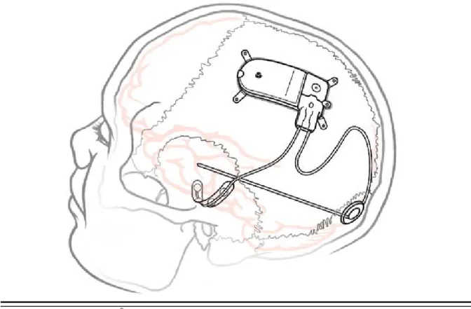
IMPLANTED RNS®SYSTEM
Figure 1: The Implanted RNS® System.
RNS®SYSTEM DESCRIPTION
The RNS® System automatically delivers responsive electrical stimulation to reduce the frequency of partial onset seizures. Note that the RNS® System is not a seizure detection device. The RNS® System comprises sterile, implantable and non-sterile, external products.
Implantable RNS® System Products The sterile, implantable products are the
• RNS® Neurostimulator
• NeuroPace® Cortical Strip Lead(s) and NeuroPace® Depth Lead(s)
• Implantable components and accessories External RNS® System Products
The non-sterile, external products are the
• NeuroPace® Programmer (laptop computer with proprietary software) and telemetry component (wand model W-02) used for communication with the implanted RNS® Neurostimulator
• NeuroPace® Patient Data Management System (PDMS) used for storage and access to historical neurostimulator and patient data
Responsive Neurostimulator System
20
• NeuroPace® Remote Monitor (laptop computer with proprietary software) and telemetry component (wand model W-02) used by the patient to gather information from the implanted RNS® Neurostimulator and upload it to the NeuroPace® Patient Data Management System. For additional information, refer to the remote monitor user manual.
• Magnet used by the patient to withhold therapy or to trigger electrocorticographic (ECoG) storage
Figure 2: RNS® Neurostimulator with two NeuroPace leads.
Cortical Strip Lead
Connector Cover Depth Lead
Lead Strain Relief
Depth Lead Depth Lead
Responsive Neurostimulator System
21
Theory of Operation
The RNS® Neurostimulator and implanted intracranial leads are designed to monitor electrical activity of the brain and deliver therapy in the form of electrical stimulation when appropriate. The
neurostimulator is implanted in the patient and communicates with the programmer (and remote monitor).
Figure 3: The RNS® Neurostimulator senses and delivers therapy via the implanted patient leads. Communication with the neurostimulator is available using the programmer (and remote monitor).
Responsive Neurostimulator System
22
RNS®NEUROSTIMULATOR
RNS® Neurostimulator (Model RNS-300M)
The NeuroPace® RNS® Neurostimulator is a responsive electrical stimulation medical device. The neurostimulator senses and records electrocorticographic (ECoG) patterns from up to four amplifier channels. Upon detection of previously identified ECoG patterns, the neurostimulator delivers short trains of current pulses through the leads to interrupt those ECoG patterns. This is referred to as responsive electrical stimulation.
The RNS® Neurostimulator is a battery powered, microprocessor-controlled medical device that is surgically implanted in the cranium and is covered by the scalp. The neurostimulator is connected to one or two leads that are surgically implanted within (depth lead) or on the surface (cortical strip lead) of the brain in the area of the epileptic seizure focus. Each lead contains four electrodes that can be assigned to one or two of four amplifier channels.
The RNS® Neurostimulator can be programmed to monitor and deliver responsive stimulation to one or two epileptic foci. Up to five individually configured sequential stimulations can be delivered when a specific ECoG pattern is detected. Each stimulation can contain two bursts that can be independently configured.
The RNS® Neurostimulator can store segments of electrocorticographic activity (electrocorticograms, ECoGs), neurostimulator status indicators, and records of events (including detection and therapies) detected by the neurostimulator. The neurostimulator can store up to a maximum of 30 minutes of ECoG activity segments.
A test stimulation function allows the user to test the current output of the neurostimulator and its effect on the patient
WARNING: COMPATIBILITY WITH SIMILAR IMPLANTABLE PRODUCTS
The NeuroPace® RNS® Neurostimulator, NeuroPace® Cortical Strip Lead, and NeuroPace® Depth Lead are not compatible with non-NeuroPace leads and / or pulse generators. Incompatible configurations may cause damage to the products and may result in unsafe current densities delivered to the patient.
RNS®SYSTEM COMPONENTS AND ACCESSORIES
Cranial Prosthesis (Model P-01)
The cranial prosthesis occupies a vacant ferrule if the neurostimulator has been explanted and not replaced.
Craniectomy Template (Model CT-01)
The craniectomy template may be used as a pattern to mark and delineate the shape of the ferrule on the skull prior to making a craniectomy.
Connector Cover (Model CC-01)
The connector cover secures the proximal lead contacts to the neurostimulator. Connector Plug (Model CP-01)
Responsive Neurostimulator System
23
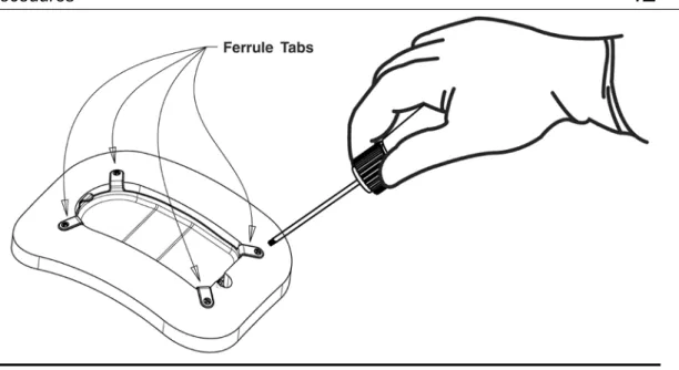
Ferrule and Ferrule Clamp (Model F-01 and Model FC-01)
The ferrule is installed in a craniectomy to secure and mechanically support the RNS®
Neurostimulator in the skull. The ferrule clamp is used to secure the neurostimulator to the ferrule. Lead Strain Relief (Model LSR-01)
The lead strain relief supports the proximal end(s) of the lead(s) at their exit from the neurostimulator connector cover, protecting the lead from stress near the connector.
Magnet (Model M-01)
The magnet is a doughnut-shaped magnet which, when placed over the implanted RNS®
Neurostimulator, suppresses therapy as long as the magnet is in position and, if the neurostimulator is programmed to do so, triggers an electrocorticogram (ECoG) storage.
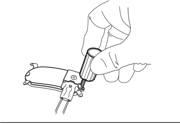
Torque Driver (Model TD-01)
The torque driver is used to tighten the screw that secures the connector cover to the neurostimulator and to tighten the ferrule clamp that secures the neurostimulator to the ferrule.
NEUROPACE®CORTICAL STRIP LEAD
The NeuroPace® Cortical Strip Lead is intended for subdural implant to provide an interface through which electrical activity of the brain can be monitored and electrical stimulation can be delivered. Cortical Strip Leads
NeuroPace® Cortical Strip Leads are available in the following lengths: 15 centimeters (model CL-315-10)
25 centimeters (model CL-325-10) 35 centimeters (model CL-335-10)
There are four electrodes spaced 10 millimeters apart from each other. All four electrodes can be configured for sensing, detection, and stimulation.
WARNING: COMPATIBILITY WITH SIMILAR IMPLANTABLE PRODUCTS
The NeuroPace® RNS® Neurostimulator, NeuroPace® Cortical Strip Lead, and NeuroPace® Depth Lead are not compatible with non-NeuroPace leads and / or pulse generators. Incompatible configurations may cause damage to the products and may result in unsafe current densities delivered to the patient.
NEUROPACE®DEPTH LEAD
The NeuroPace®Depth Lead is intended for implant into the brain to provide an interface through which electrical activity of the brain can be monitored and electrical stimulation can be delivered. Depth Leads
NeuroPace® Depth Leads are available in the following configurations: 30 centimeter length, 10 millimeter electrode spacing (model DL-330-10) 30 centimeter length, 3.5 millimeter electrode spacing (model DL-330-3.5) 44 centimeter length, 10 millimeter electrode spacing (model DL-344-10)
Responsive Neurostimulator System
24
44 centimeter length, 3.5 millimeter electrode spacing (model DL-344-3.5) All four electrodes can be configured for sensing, detection, and stimulation.
WARNING: COMPATIBILITY WITH SIMILAR IMPLANTABLE PRODUCTS
The NeuroPace® RNS® Neurostimulator, NeuroPace® Cortical Strip Lead, and NeuroPace® Depth Lead are not compatible with non-NeuroPace leads and / or pulse generators. Incompatible configurations may cause damage to the products and may result in unsafe current densities delivered to the patient.
LEAD COMPONENT AND ACCESSORIES
Tunneling Tool (Model TT-01), Tunneling Tool Tip (Model TTT-01), Tunneling Straw (Model TTS-01) The tunneling tool components are used to tunnel an implanted lead from its cranial exit point, through a sub-galeal pathway, to the implanted RNS® Neurostimulator location.
Lead Cap (Model LC-01)
The lead cap protects the proximal end of a lead when it is not connected to the RNS® Neurostimulator.
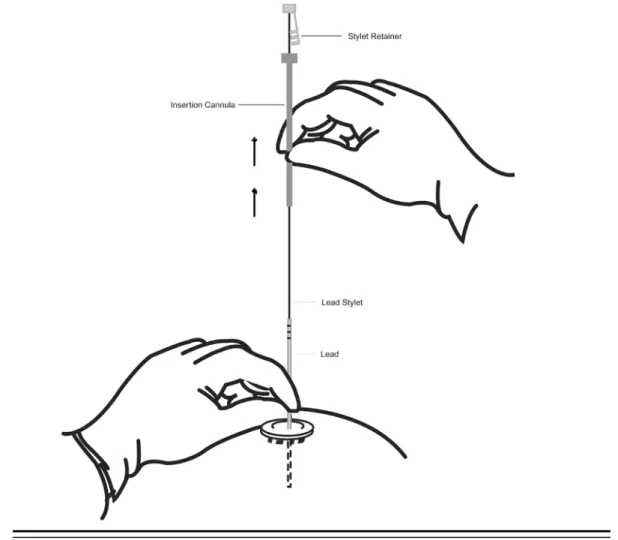
Stop Gauge (Model SG-01)
The stop gauge is placed on a depth lead prior to implantation to indicate the appropriate depth of its insertion.
Suture Sleeve (Model SS-01)
The suture sleeves protect the lead body when sutures are used to secure a lead.
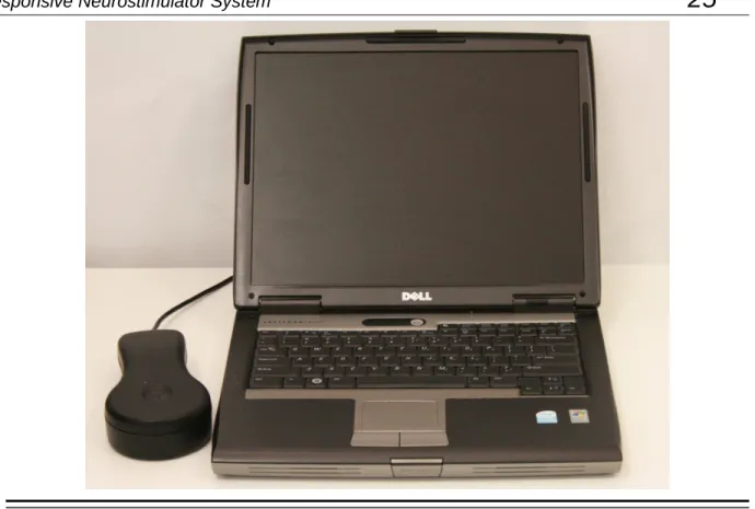
NEUROPACE®PROGRAMMER
NeuroPace® Programmer (Model PGM-300)
The programmer includes a laptop personal computer that runs software developed by NeuroPace, and uses custom telemetry components to communicate with the RNS® Neurostimulator.
The programmer is used to prescribe how the neurostimulator operates. Settings include, but are not limited to, the implanted system configuration, detection settings adapted to the patient's ECoG patterns, ECoG record storage, and the settings of the therapies.
The NeuroPace® Programmer may also be used on its own to review previously retrieved neurostimulator activity information, perform detection analysis, and to communicate with the NeuroPace® Patient Data Management System (PDMS) via connection over the Internet.
Responsive Neurostimulator System
25
Figure 4: The NeuroPace® Programmer and wand are used to communicate with the RNS® Neurostimulator.
TELEMETRY WAND
Wand (Model W-02)
The wand is placed over the implanted RNS® Neurostimulator to facilitate communication with the programmer. It is connected to the laptop component of the programmer via a USB cable.
NEUROPACE®PATIENT DATA MANAGEMENT SYSTEM
NeuroPace® Patient Data Management System (Model 4340)
The Patient Data Management System (PDMS) maintains patient and product data obtained from the programmer and remote monitor.
Authorized users may access the PDMS via the Internet using a personal computer. An electronic signature in the form of a user name and password are required for user authentication. For additional information on using the PDMS, refer to the Patient Data Management System User Manual.
Responsive Neurostimulator System
26
STERILIZATION,STORAGE, AND HANDLING
Handling Products
The products of the RNS® System are to be handled with extreme care. • Handle the lead with care.
• Bending, kinking, and stretching of the lead may cause lead damage. • Do not reinsert stylet into the lead once it has been removed.
• Do not tighten sutures over the lead body.
• Only use the torque driver to secure the connector cover. Resterilization of Implantable Products
The RNS® Neurostimulator is provided sterile. DO NOT RESTERILIZE. Implantable RNS® System products are single-use-only. Do not resterilize or re-implant any explanted products of the RNS® System. Return the explanted neurostimulator and leads to NeuroPace.
“Use by” Date
Do not implant or use any system component after the “Use by” date. Return all such product to NeuroPace.
Damaged Packaging
Prior to product use, inspect the sterile packages for seal integrity. If the packaging appears to be wet, punctured, or damaged, the contents may no longer be sterile and these product(s) should be returned to NeuroPace for replacement.
Product Storage
Components should be stored in a clean and secure area with a room temperature of approximately 14 to 28 degrees Celsius.
Explant and Disposal
Program all detection and therapy functions to DISABLED prior to explanting and shipping the RNS® Neurostimulator. Return the explanted neurostimulator and leads to NeuroPace. NeuroPace will provide shipping containers if requested.
DO NOT incinerate the neurostimulator; explosion can occur if the neurostimulator is exposed to incineration or cremation temperatures.
Wand Cleaning and Sterilization
The wand can be cleaned by wiping with water. It can be placed in a sterile bag for use in the sterile field. DO NOT STERILIZE the wand.
Electrostatic Discharge (ESD) / Static Electricity
The ports on the programmer laptop may be sensitive to electrostatic discharge (ESD) / static electricity. Handle the programmer laptop ports carefully. If exposed to electrostatic discharge, the programmer may experience telemetry artifacts or errors, or may freeze. In the event of a
Responsive Neurostimulator System
27
RNS®SYSTEM LONGEVITY
RNS® Neurostimulator Battery
Neurostimulator longevity depends on the amount of stimulation delivered to the patient. Each time the neurostimulator delivers stimulation, a small amount of charge is drained from the battery. The battery information for each neurostimulator can be obtained through the PDMS. Battery
measurements can be taken using a programmer.
RNS® Neurostimulator Battery Life Estimation for Model RNS-300M
The following battery information is theoretical. In actual use, the programmed stimulation parameters and other factors, such as lead impedance, may vary. Therefore, the following battery longevity estimates from beginning of battery life to end of service were calculated utilizing three patient-use profiles: Low (5th Percentile), Medium (50th Percentile), and High (95th Percentile). It is important to note that the RNS® Neurostimulator is a responsive neurostimulator and does not have high, medium, and low operating settings.
Calculated Battery Longevity to End of Service (EOS) (Model RNS-300M)
Patient Use Profile Battery Capacity (mAh) Longevity Estimate * (years) Low (5th Percentile) 705 4.26 Medium (50th Percentile) 705 3.91 High (95th Percentile) 705 2.64
* Estimated battery longevity following 9 months of shelf storage.
These patient-use profiles were derived from data collected during the RNS® System Clinical Investigations in Epilepsy through May 12, 2011. The data (battery use in mAh/day) at the 5th, 50th, and 95th percentile levels were used to calculate the battery longevity estimates presented in the table above.
These same data have been converted into the profiles in the table below to illustrate typical therapy parameters that would lead to the specified battery use. (Note that, e.g., half as many bursts per day with twice the burst duration would provide identical battery life.)
Patient Use Profiles
Parameter Unit Low
(5th Percentile) Medium (50th Percentile) High (95th Percentile) Current mA 6 6 12 Frequency Hz 200 200 200
Pulse Width µsec 160 160 200
Burst Duration msec 100 100 100
Responsive Neurostimulator System
28
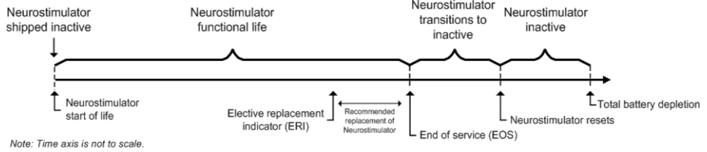
Elective Replacement Indication (ERI)
The programmer reports the neurostimulator battery voltage each time it is interrogated. The elective replacement indicator is displayed upon interrogation of the neurostimulator. The neurostimulator should be replaced promptly after the ERI notification. The ERI indicator is displayed approximately three months prior to the neurostimulator end of service (see below).
End of Service (EOS)
End of service is the point at which the RNS® Neurostimulator is no longer guaranteed to meet its specifications. The neurostimulator resets (and no longer detects or stimulates) within one week of EOS detection. The programmer can be used to indicate when the EOS battery level has been reached.
RNS® Neurostimulator Reset
When the neurostimulator resets, all of the neurostimulator functions are suspended except telemetry and battery measurement functions. The neurostimulator does not detect or deliver stimulation, measurements are disabled (except battery), and no records are stored. The neurostimulator resets if an internal problem is detected or the neurostimulator battery voltage is at end of service. The
programmer notifies the user of a reset upon neurostimulator interrogation. RNS® Neurostimulator Inactive
The sterile, packaged neurostimulator is shipped in an inactive state during which all neurostimulator functions are suspended except telemetry and battery measurement functions. The neurostimulator does not detect or deliver stimulation, measurements are disabled (except battery), and no records are stored. The first interrogation of a sterile, packaged neurostimulator by the programmer activates the neurostimulator.
Figure 5: The sequence of RNS® Neurostimulator battery life events.
PRODUCT REGISTRATION
Registration of implanted medical products is required by U.S. federal regulations. A registration form is provided with the RNS® Neurostimulator and leads. Complete the registration information as soon as possible and return it to NeuroPace.
Clinical Use of the RNS
®System
29
C
LINICAL
U
SE OF THE
RNS
®S
YSTEM
IDENTIFYING CANDIDATES FOR THE RNS®SYSTEM THERAPY
Clinical trials have shown that the RNS® System is safe and effective in patients who are 18 years of age or older with disabling partial onset seizures from no more than two foci and have medically intractable epilepsy, defined by the International League Against Epilepsy (ILAE) as a failure to control seizures after 2 seizure medications that have been appropriately chosen and used. Patients benefiting from the RNS® System have partial onset epilepsy with one or more of the following seizure types:
• Simple partial motor: seizures characterized by alteration in motor function without change in awareness
• Complex partial: seizure includes impairment in awareness
• Generalized tonic, clonic or tonic-clonic seizures
The RNS® System is appropriate only in patients whose seizures begin in one or two foci that can be implanted with NeuroPace® Depth Leads and/or NeuroPace® Cortical Strip Leads. Only 2 leads can be connected to the neurostimulator and therefore detection and stimulation can occur in no more than 2 locations.
The RNS® System should not be considered in patients who are likely to require MRIs of the brain in the future because an MRI is contraindicated in patients implanted with the RNS® System. The RNS® System is also contraindicated in patients who have implanted medical devices that deliver electrical energy to the head. Patients who have medical or neurological conditions that place them at high risk for surgical complications are not good candidates for the RNS® System. For a complete list see the
Contraindications section.
LOCALIZING THE SEIZURE FOCUS AND PLANNING LEAD LOCATION
The RNS® System delivers responsive stimulation to one or two seizure foci. In order to accomplish this, a precise detection of the electrocorticographic activity of interest must be achieved to provide stimulation to the seizure focus. If electrocortiocographic activity of interest is not detected as
intended, and / or stimulation cannot be delivered to the focus, it is possible that the seizure focus will not be adequately treated. Therefore, it is essential that the seizure focus be sufficiently well localized to guide placement of the lead or leads.
Localization of the seizure focus is accomplished using standard localization tests available at qualified Comprehensive Epilepsy Centers. This will always include in-patient video-EEG monitoring with scalp electrodes with or without supplemental electrodes such as sphenoidal electrodes, as well as MRI with appropriate magnet strength and sequences for the detection of mesial temporal
sclerosis and other common epileptogenic lesions.
Non-invasive EEG and MRI imaging may be adequate to determine the number and location of seizure foci. However, some patients may require additional testing with video-EEG monitoring with intracranial electrodes to identify or refine the localization of the seizure focus. This may also include intraoperative or extraoperative stimulation with subdural electrodes for functional cortical mapping. Additional imaging studies may include Positron Emission Tomography (PET), ictal single photon emission computed tomography (SPECT), functional MRI (fMRI) or magnetoencephalography (MEG). Neuropsychological testing and intracarotid amytal (Wada) testing is included in many
Comprehensive Epilepsy Centers’ localization evaluation.
Patients with medically refractory partial epilepsy following resective surgery should have had appropriate studies following the surgery to adequately localize the seizure focus or foci prior to implantation of the RNS® System.
Clinical Use of the RNS
®System
30
The leads to be implanted are selected based on the location of the seizure focus. NeuroPace® Cortical Strip Leads are recommended for seizure onsets on the surface of the cortex, where the cortical strip leads may be placed over the focus. NeuroPace® Depth Leads are recommended for seizure onsets beneath the cortical surface, such as within the mesial temporal lobe or within
subcortical lesions such as dysplasias, where the depth lead may be placed within the seizure focus. Several lead lengths are available (refer to the NeuroPace® Cortical Strip Lead section and the
NeuroPace® Depth Lead section). The lead model selected should be the appropriate length to
reach from the seizure focus to the neurostimulator with as little excess lead as possible.
Up to four leads can be implanted (no more than two depth leads). For example, two depth leads and two cortical strip leads, or one depth lead and three cortical strip leads could be implanted. Only two leads can be connected to the neurostimulator at a given time; unconnected leads should be capped. Leads connected to the neurostimulator can be changed at a subsequent procedure if desired.
PATIENT TRAINING
• Prior to the implant surgery, train the patient and / or caregiver how to use the NeuroPace® Remote Monitor and wand, as well as how to use the magnet to mark clinical seizures.
• After implantation, provide the patient with the medical implant identification card.
• Instruct the patient and/or caregiver to interrogate the neurostimulator every day using the remote monitor and wand, and to synchronize the remote monitor with the PDMS at least once a week (preferably every day).
OVERVIEW OF IMPLANTATION AND PROGRAMMING OF THE RNS®SYSTEM
Implanting the RNS® Neurostimulator and Leads
The RNS® Neurostimulator is cranially implanted. A ferrule is secured to a full thickness craniectomy and then the neurostimulator is placed within the ferrule. The recommended location of the
neurostimulator is in the parietal skull but this can be modified based on the location of the leads and the curvature of the patient’s skull. The neurostimulator may be implanted and secured in the ferrule before or after the Leads are implanted. Instructions for implanting the RNS® Neurostimulator are provided in the Surgical Procedures section.
Leads are placed using standard neurosurgical techniques. NeuroPace® Depth Leads may be implanted using standard stereotactic techniques through a burr hole in the skull, then secured by a burr hole cover such as the NeuroPace® Burr Hole Cover Model 8110. NeuroPace® Cortical Strip Leads are implanted through a craniectomy, in a manner similar to standard strip lead placements, then secured using suture sleeves. Leads are tunneled under the scalp to the craniectomy.
Instructions for implanting NeuroPace® Depth Leads and NeuroPace® Cortical Strip Leads are provided in the Surgical Procedures section.
When the implantation procedure is complete and while still in the operating room, the programmer is used to test lead impedances and to capture real-time ECoG to ensure that there is good lead-tissue contact. Instructions for checking lead impedances and for real-time ECoG are provided in the
Impedance Measurements section and the section describing Capturing Real-time ECoGs.
Recommended Initial Detection and ECoG Storage Settings
The neurostimulator is initially programmed in the operating room to detect electrocorticographic activity (ECoG) and to store ECoG segments.
A bipolar electrode montage is used for sensing. The sensing montage must be configured in a bipolar manner. The recommended initial montage is to sense between neighboring contacts. For
Clinical Use of the RNS
®System
31
example, channel 1 should be programmed to sense the difference between electrode 1 on lead 1 and electrode 2 on lead 1.
The recommended initial detection settings are the default settings in the programmer. These settings detect changes in frequency and power of the ECoG (line Length detector with a 75% threshold). The neurostimulator is programmed to store segments of the ECoG when specific events occur. The physician selects which types of events trigger ECoG storage – these are called ECoG triggers. There are three recommended ECoG triggers to be programmed at implant. The first is a magnet swipe by the patient, which could indicate that a clinical seizure has occurred. The others are saturation (high amplitude ECoG) and long episode (sustained changes in the ECoG), both of which could indicate an electrographic seizure.
Instructions for setting up the initial detection and ECoG storage parameters are provided in the sections titled Setting up Detection and Setting up ECoG Storage.
After implantation, the patient should be instructed to interrogate their neurostimulator daily using the remote monitor and to transfer that data to the PDMS at least weekly so that sufficient data are stored for the physician’s review. The patient should be seen approximately 2 weeks after implant so that the physician can review the detections using the stored ECoGs.
Recommended Initial Responsive Therapy Settings
Responsive stimulation therapy should be enabled once the physician has determined the electrographic activity of interest is being detected.
Recommended initial responsive therapy settings are a frequency of 200 Hz, pulse width of 160 µsec and burst duration of 100 ms. Current amplitude should be initially programmed at 1.0 mA. In general, stimulation should be delivered to the leads and electrodes from which electrographic patterns of interest are observed. For example, if electrographic activity of interest is observed on all channels, then the stimulation pathway should be configured to stimulate across all electrodes. However, if electrographic activity of interest is observed on only 2 channels, then the stimulation pathway should be configured such that current is delivered through only those electrodes with electrographic activity of interest.
Recommended Initial Responsive Therapy Settings
Frequency 200 Hz
Pulse Width 160 µs
Burst Duration 100 ms
Current 1.0 mA and adjusted as necessary
Electrodes Those from which patterns of interest are observed
Stimulation should be tested while the patient is in the physician’s office by using the therapy testing function. This ensures that the patient tolerates the stimulation settings and that there are no undesired changes in the ECoG. If the patient cannot tolerate the stimulation settings or there are changes of concern in the ECoG, the current amplitude should be reduced.
Instructions for setting up the initial stimulation parameters are provided in the section titled Setting
Clinical Use of the RNS
®System
32
Modifying Detection and Responsive Therapy Settings
Once the neurostimulator is programmed to provide responsive stimulation, the patient should be seen at approximately 3 month intervals to determine whether detection and/or responsive therapy settings should be modified. At each patient visit, the physician reviews ECoGs that are stored on the PDMS or programmer.
The physician decides whether the detection settings should be modified based on the ECoG review. In addition to the line length detector, the neurostimulator has bandpass and area detectors
(described in the section titled Setting up Detection). If the physician wishes to change which ECoG patterns are detected, the detectiors may be adjusted or a different detection tool may be selected. For example, if the physician wishes to detect smaller changes in the ECoG amplitude, the line length detector can be programmed to be more sensitive. If the physician wishes to detect specific ECoG frequencies, the bandpass detector could be used. Different detection settings can be simulated on the ECoG segments that have been stored on the PDMS or programmer. This allows the physician to see how the modified detection settings perform, before deciding to program these settings into the neurostimulator.
Instructions for modifying detection settings are provided in the section titled Setting up Detection.
The physician may choose to modify stimulation to improve the patient’s clinical response, Although modifications can be made to the stimulation frequency, burst duration or pulse width, it is
recommended that initial modifications be to increase the current amplitude by 0.5 mA increments, with each stimulation setting tested using the therapy testing function to ensure that it is well tolerated by the patient and there are no undesired changes in the ECoG such as afterdischarges.
Instructions for modifying responsive therapy settings are provided in the section titled Setting up
Surgical Procedures
33
S
URGICAL
P
ROCEDURES
Implanting physicians should have adequate experience in the implantation of subdural and stereotactic implantation of intraparenchymal electrodes, in the surgical treatment of intractable epilepsy, have completed the NeuroPace® RNS® System training program, and be thoroughly familiar with all product labeling.
PRE-IMPLANT
Patient and Family Information
The potential risks and benefits of implanting the RNS® System and responsive electrical stimulation therapy should be discussed with the patient, legal guardians, and family members before the implant procedure and during follow-up. The patient should be counseled that diathermy procedures, Magnetic Resonance Imaging (MRI) procedures, ElectroConvulsive Therapy (ECT) and Transcranial Magnetic Stimulation (TMS) are contraindicated, even if the neurostimulator is turned off or has been removed, or if any leads or any part of a lead remain. The patient should also be counseled on other medical procedures to avoid and on RNS® System care and environmental hazards. The RNS® System Patient Manual outlines this information and should be provided to and reviewed with the patient prior to the RNS® System implant.
Pre-surgical Antibiotics
To reduce the risk of infection, it is recommended that antibiotics be administered prior to surgery. Product Preparation
1. Order and obtain the RNS® Neurostimulator and appropriate lead(s) for the implant, as determined in the surgical planning for this procedure.
2. Before opening the RNS® Neurostimulator and leads packaging, verify model numbers, use-by dates and product sterility.
3. It is recommended that additional products be available in case product sterility or function is compromised.
Number of Leads
A maximum of four leads may be implanted, only two of which may be depth leads. Only two leads may be connected to the neurostimulator at any time; it is recommended that a unique identifier be attached to each lead.
Programmer Preparation
The programmer should be in the operating room. It is used for the following activities:
• Assigning lead type(s) and serial number(s) to the corresponding neurostimulator port(s). • Programming the montage, detection and ECoG storage.
• Confirming lead integrity by performing lead impedance measurements. • Viewing real-time ECoGs to verify sufficient lead-tissue contact.
Surgical Procedures
34
Pre-Implant RNS® Neurostimulator Interrogation
The sterile, packaged neurostimulator should be interrogated using the programmer prior to implantation to verify battery voltage.
To interrogate the sterile, packaged neurostimulator: 1. Turn on the programmer and login.
2. Place the wand over the neurostimulator, which is visible from the bottom (clear side) of the neurostimulator sterile packaging tray.
3. Select the INTERROGATE button on the programmer MAIN MENU screen.
4. Review MEASURED BATTERY VOLTAGE on the summary screen. If interrogation fails or the battery voltage is < 2.85 V, return the neurostimulator to NeuroPace, and continue the procedure with another sterile, packaged neurostimulator.
To manually measure battery voltage after interrogating: 1. Go to the REVIEW DATA tab.
2. Select the MEASUREMENTS tab.
3. Select the MEASURE button in the battery section of the MEASUREMENTS tab screen. Opening the Sterile Product Package
Prior to opening the sterile packaging, inspect for any damage or breach in package seal
integrity. If the packaging appears to be wet, punctured, or damaged, the contents may no longer be sterile. Product(s) with damaged packaging should be returned to NeuroPace for replacement. Packages containing sterile product(s) should be opened into a sterile surgical field. Products should not leave the sterile surgical field once the package is opened.
Figure 6: Handing the sterile product tray to a surgeon in the sterile field.
Bone screws
It is recommended that 1.5 mm diameter, 4 mm long bone screws (not provided) be used to secure the ferrule to the skull. If necessary, 5 mm or 7 mm long bone screws may be used. If the 1.5 mm diameter screws do not securely anchor the ferrule in the skull, 1.8 mm diameter screws should be used.
Surgical Procedures
35
RECOMMENDED IMPLANT PROCEDURE FLOW CHART
Make scalp incision at the desired implant location
Trace the Craniectomy Template on the skull at the implant location
Neurostimulator Implant
Make craniectomy around template drawing
Secure the Ferrule in the craniectomy Perform appropriate craniotomy
to implant Cortical Strip Lead
Separate and resect dura
Implant Cortical Strip Lead subdurally
Stabilize Cortical Strip Lead using Suture Sleeves as appropriate Attach Burr Hole Cover
base to skull
Advance insertion cannula to appropriate depth
Advance Depth Lead to target depth
Secure Depth Lead using Burr Hole Cover Cap Make Burr Hole at appropriate location to implant Depth Lead
Cortical Strip Lead Implant Depth Lead Implant
Tunnel Leads to Neurostimulator
Place the excess Lead under the scalp in a pocket area near the burr hole or craniectomy area. Do not place the Leads on or around the Neurostimulator
Insert the Lead(s) into the Connector Cover and secure the cover onto the Neurostimulator. A Connector Plug must be placed in the
Connector Cover if only one Lead is implanted.
Secure the Neurostimulator in the Ferrule
Using the Programmer, confirm the integrity of the system
Record the Lead serial numbers and Neurostimulator port numbers in the Programmer