Development of Standard Specification and Standard
Details for Local Highway Maintenance
Appendix 1 – Specification & Notes for Guidance
i
Development of Standard Specification and Standard Details for Local Highway Maintenance Appendix 1 – Standard Specification and Notes for Guidance Version 1 - November 2012 Although this report was commissioned by the Department for Transport (DfT), the
findings and recommendations are those of the authors and do not necessarily represent the views of the DfT. The information or guidance in this document (including third party information, products and services), is provided by DfT on an 'as is' basis, without any representation or endorsement made and without warranty of any kind whether express or implied.
Department for Transport Great Minster House 33 Horseferry Road London SW1P 4DR Telephone 0300 330 3000 Email: Website © Crown Copyright 2012
Copyright in the typographical arrangement rests with the Crown.
You may re-use this information (not including logos or third-party material) free of charge in any format or medium, under the terms of the Open Government Licence. To view this
licence, visit
the Information Policy Team, The National Archives, Kew, London TW9 4DU, or e-mail:
Where we have identified any third-party copyright information you will need to obtain permission from the copyright holders concerned.
ii
Development of Standard Specification and Standard Details for Local Highway Maintenance Appendix 1 – Standard Specification and Notes for Guidance Version 1 - November 2012
REVISION SCHEDULE
Rev Date Details Prepared by Reviewed by Approved by
This document is released as an Interim Document to allow its use by local highway authorities as early enablers in the development of their term service contracts, feeding into the ongoing development of the Highways Maintenance Efficiency Programme Standard Term Maintenance Contract and Document Compiler work package.
If you wish to make a comment or contribute to the development of the document, please send an email to
iii
Development of Standard Specification and Standard Details for Local Highway Maintenance Appendix 1 – Standard Specification and Notes for Guidance Version 1 - November 2012
CONTENTS
FOREWORD IV
INTRODUCTION 1
SERIES 500 – DRAINAGE AND SERVICE DUCTS 5 SERIES 700 – ROAD PAVEMENTS - GENERAL 90 SERIES 900 – BITUMINOUS BOUND MATERIALS 93 SERIES 1100 – FOOTWAYS AND PAVED AREAS 152 SERIES 1200 – TRAFFIC SIGNS ROAD MARKINGS AND ROAD STUDS 159 SERIES 1300 – ROAD LIGHTING COLUMNS AND BRACKETS 161
SERIES 1700 – STRUCTURAL CONCRETE 171
SERIES 1800 – STRUCTURAL STEELWORK 199
WINTER MAINTENANCE MATERIALS 201
iv
Development of Standard Specification and Standard Details for Local Highway Maintenance Appendix 1 – Standard Specification and Notes for Guidance Version 1 - November 2012
FOREWORD
ABOUT THE HIGHWAYS MAINTENANCE EFFICIENCY
PROGRAMME
The Highways Maintenance Efficiency Programme (HMEP) is a sector-led transformation initiative that will maximise returns from investment and deliver efficiencies in highway maintenance services. The Programme started in April 2011 with sponsorship from the Department for Transport and is intended to run until 2018.
The Programme is offering local highway practitioners benefits from different ways of working. The vision is that over time, those involved in highways maintenance delivery, the local authorities as clients and their service providers, be they from the private or public sector will adopt an ambitious and longer-term approach to enable them to:
• Continuously find new and improved ways of delivering services to highway users and managing highways assets.
• Make use of collaborative partnerships to improve processes and outcomes. Deliver a sustainable balance between meeting the needs of highways users, improving quality and minimising costs.
The overall programme has been developed by the Programme Board through key personnel who support HMEP’s development. This will ensure that:
• The Programme is truly being driven by what the whole sector needs and wants (‘by the sector for the sector’).
• The solutions identified by the sector are relevant, realistic, repeatable, scalable and sustainable.
• HMEP is benefits-led, driving true transformation of the sector with tangible efficiency gains and a lasting legacy.
As a transformation initiative HMEP is targeting the ways local highway authorities conduct their business. It invites the sector to adopt new ways of working to deliver efficiency savings through:
• Collaboration & Change - looking at how alliances between authorities, and clients and their providers, can be formed to deliver efficiencies in the delivery of highway maintenance services. Other projects are looking at changing business processes; for instance by applying Lean thinking to the processes behind service delivery and how services or processes can be streamlined to realise efficiencies.
v
Development of Standard Specification and Standard Details for Local Highway Maintenance Appendix 1 – Standard Specification and Notes for Guidance Version 1 - November 2012
• Procurement, Contracting and Standardisation – advising on the routes to procurement enabling authorities to determine how their current service is aligned to current thinking and which is the best procurement option to realise their future service ambitions. It also provides the tools so that efficiencies can arise through the use of, for instance, a standardised form of contract and highway maintenance specification which are better aligned to the activities that local highway authorities undertake.
• Asset Management – by providing advice to the sector in the form of updated asset management guidance; for both a simplistic and, where appropriate, more complex lifecycle planning tool to determine whole life asset costs, thus moving away from a reactive to a longer-term approach for maintaining highways assets. To provide training specifically targeted at practitioners to help them move towards an asset management approach and to adopt the new HMEP guidance and tools.
• Benchmarking & Performance – collecting, sharing and comparing performance data on Customer/Quality/Cost to help both understanding to show how effective local highway authorities are in delivering Value for Money services and drive targeted efficiencies.
Products and tools are being developed for each of these themes and are being designed to be interdependent, but complementary, so that authorities can maximise their returns from their investments.
ABOUT THIS TOOLKIT
The HMEP survey of the sector of October 2011 indicated that 97% of those local highway authorities responding wanted a specification that was more aligned to the maintenance activities that they undertake, as opposed to the current Specification for Highway Works which is aimed at new road construction. In response to this, HMEP has prepared this guidance for the development of a Standard Specification and Standard Details for Local Highway Maintenance.
This is the first release of the document and is aimed at the areas where local highway authorities incur the greatest maintenance expenditure; namely in highway drainage, kerbing and footway works, bituminous surfacing, structural concrete, structural steelwork and winter maintenance activities. The guidance is based on documents returned as part of each authority’s response to the survey. The content of this guidance draws on the good practice within specifications developed for recent tenders and for contracts that are about to be procured, making the content as current as possible.
This guidance represents the beginning of a review of the full range of services local highway authorities undertake. A new product is currently in development that will expand on the scope of the guidance to all series of the specification and incorporate outcome specifications. This is programmed for release towards the end of 2013. However, the sector is encouraged to start to move towards a standardised approach by using this document.
vi
Development of Standard Specification and Standard Details for Local Highway Maintenance Appendix 1 – Standard Specification and Notes for Guidance Version 1 - November 2012 A consistent approach will help to align the documents to the range of services that local
highway authorities undertake with associated pricing schedules, method of measurement and bill item generation. This product will be presented with the HMEP suite of procurement documents (IfT, OJEU, PQQ and Form of Contract) within a document compiler platform to enable local highway authorities to procure Term Service Contracts as well as individual projects while moving towards an e-tendering solution. Significant savings are expected through adopting a standard specification across the sector. The many bespoke forms that currently exist will be rationalised to a single common form. The HMEP version will also be maintained centrally and be updated regularly, saving the resource commitment within each authority to update and maintain their own standard forms. There is also the potential for wider savings throughout the supply chain as all become familiar with the new specification and move away from bespoke forms towards a consistent approach. Authorities are therefore encouraged to start using this guidance now to move towards the aims and ambitions of the wider programme for the sector.
Authorities should resist the temptation to bespoke the specification to suit their particular local needs. If you consider that certain aspects need to be included, please relay the information with the rationale for its inclusion back to the Programme for consideration. If deemed appropriate, it will be included within the next update.
ABOUT THIS DOCUMENT
This document forms Appendix 1 to the Guidance for the Development of Standard Specification and Standard Details for Local Highway Maintenance Contracts, and contains the Specification and Notes for Guidance clauses developed as part of the HMEP.
Users should refer to the original document for references to the specification and notes for guidance.
COMMENTS AND FEEDBACK
The HMEP Programme Board would welcome any comments and feedback on this document so that the final product may be reviewed, improved and refined to give the sector the best advice possible. If you wish to make comments please email them to
[email protected]
with the header ‘Feedback on the Standard1
Development of Standard Specification and Standard Details for Local Highway Maintenance Appendix 1 – Standard Specification and Notes for Guidance Version 1 - November 2012
INTRODUCTION
The Guidance for the Development of Standard Specification and Standard Details for local highway maintenance Contracts has been prepared on behalf of the Highways Maintenance Efficiency Programme to provide a series of standard specification items and drawings for local highway authority maintenance works.
The Department for Transport published Manual of Contract Documents for Highways Works was originally developed for the specification of new works on the motorway and trunk road systems, and has been recognised that it has limitations in its use when specifying maintenance materials for local highway authorities.
Many local highway authorities have, either individually or collaboratively, developed their own variations to the Manual of Contract Documents for Highways Works, illustrating the need for specific items to cover the works undertaken on non-motorway or trunk road routes.
The Highways Maintenance Efficiency Programme (HMEP) has collated these variations, drawn the common themes from the information provided by local authorities, and identified examples of good practice. Material specifications have been standardised where possible to enable cost savings and increased confidence in material quality to be achieved through a consolidation or rationalisation of the available information.
DOCUMENT RELEVANCE
During the development of this document it has been recognised that, to bring maximum benefit to users, additional work is required to expand the current HMEP specification to cover all works undertaken by local highway authorities. In addition it is noted that the Department for Transport is in the process of updating the Specification for Highways Works. The nature and extent of this update is not known at present. As a result this document will require updating within 12 to 18 months.
This work will contribute to a new HMEP product comprising a Standard Term Maintenance Contract and Document Compiler. The scope of this package is to provide Term Maintenance Contract, Method of Measurement and Bill of Quantities for highway maintenance services associated with two other HMEP products (the Form of Contract and Specification).
This document is therefore released as an Interim Document to allow its use by local highways authorities as early enablers in the development of their term service contracts, feeding into the ongoing development of the Highway Maintenance Efficiency Programme Standard Term Maintenance Contract and Document Compiler work package.
Following completion of the Highway Maintenance Efficiency Programme Standard Term Maintenance Contract and Document Compiler this document will be revised to take into account feedback over the development period.
2
Development of Standard Specification and Standard Details for Local Highway Maintenance Appendix 1 – Standard Specification and Notes for Guidance Version 1 - November 2012
DOCUMENT LAYOUT
The Guidance for the Development of Standard Specification and Standard Details for Local Highway Maintenance Contracts document has been developed in three sections: Section 1: Guidance for the Development of Standard Specification and
Standard Details for Local Highway Maintenance Contracts
The main document provides information on the background to the HMEP work undertaken to date, and on the development of this product.
Section 2: Appendix 1 - Specification and Notes For Guidance (This Appendix) The Standard Specification document has been sub-divided into the relevant Specification for Highways Works series. The work has been further divided within each series into:
Specification - The HMEP guidance provides two forms of specification clauses. These are numbered as HMEP Cl. Xxx, and may be used as Substitute Clauses, SR, replacing the current Specification for Highways Works Clause, or as an Additional Clause, AR, to the existing Specification for Highways Works. Where additional Notes for Guidance for the Specification clause have been provided the full specification clause has been supplied.
Notes for Guidance – Where applicable notes for guidance for the alternate clause have been produced. These are highlighted in an orange box (shown below) and follow the relevant clause. These are numbered as HMEP NG Cl. Xxx
Additional Guidance – Additional guidance notes have been included where information has been obtained that can be used to aid decisions on the adoption of specification items, or where additional guidance is available from other sources.
These are also highlighted in an orange box (as above), and are numbered as HMEP AG xxx.xx.
Section 3: Appendix 2 - Standard Details
Standard detail drawings have been prepared to supplement those provided in the Manual of Contract Documents for Highways Works Highways Construction Details and to expand on the HMEP Standard Specification above. These provide additional standard details for local highways works on non-motorway or non-trunk road systems. They include additional drainage details for minor roads and footway construction details. The standard details drawings are numbered HMEP – XXX – YYY, where XXX is the Specification for Highways Works series number, and YYY is the sequential numbering for the drawings. These are available separately from this document for download from
3
Development of Standard Specification and Standard Details for Local Highway Maintenance Appendix 1 – Standard Specification and Notes for Guidance Version 1 - November 2012 the HMEP website as .pdf and .dwg files. These drawings may be referred to either in
their original form in this document, or imported into specific contract documents.
In the event that the drawings are imported into contract documents the drawings should be renumbered as contract specific drawings in Appendix 0/4 of the new contract.
SPECIFICATION AND NOTES FOR GUIDANCE
The intention of this document is to provide a set of current standard details that can be used as a core document in specifying highway maintenance services for local highway networks, complementing local details and methods of work.
When referring to a HMEP specification clause in your documentation use the following description
“in accordance with HMEP Clause xxx”
This means that the reference in your document will be taken from the HMEP Clause, which will ensure that it is up to date with any revisions.
Alternatively, consent is given for you to copy the clause from this document into your authorities’ document. If you wish to copy items within this document this is acceptable, but will mean that your clause is only as up to date as the version of the document that you hold. References to the HMEP clause numbers should also be removed from the HMEP standard detail drawings and replaced with your clause number taken from your Specification document.
The following apply to each clause unless otherwise stated thereon:
1. Specification for Highways Works means the Specification for Highway Works published by The Stationery Office as Volume 1 of the Manual of Contract Documents for Highway Works.
2. HMEP means the Highways Maintenance Efficiency Programme Standardised Specification and Standard Details For local highway authorities
3. Reference to a Clause prefaced by Cl. is a reference to a Clause of the Specification for Highway Works.
4. Reference to a Clause prefaced by HMEP Cl. is a reference to a Clause of the Highways Maintenance Efficiency Programme Standard Specification.
5. Reference to a Numbered Appendix (e.g. Appendix 3/1) is a reference to a Numbered Appendix to the contract Specification.
The relevant publication date of each Clause is to be determined from the Schedule of Pages and Relevant Publication Dates in the Specification.
4
Development of Standard Specification and Standard Details for Local Highway Maintenance Appendix 1 – Standard Specification and Notes for Guidance Version 1 - November 2012 The relevant publication date of each British Standard (BS) and other reference
document referred to in the HCD is to be determined in accordance with Clause 004 of the Specification.
5
Development of Standard Specification and Standard Details for Local Highway Maintenance Appendix 1 – Standard Specification and Notes for Guidance Version 1 - November 2012
SERIES 500 – DRAINAGE AND SERVICE
DUCTS
Following review of the information provided by the contributing local authorities from the survey in October 2011 it became apparent that there were limited alterations to the Manual of Contract Documents for Highways Works, Specification for Highways drainage works, and that these could be attributed to individual projects or local variations. For the purposes of the project these were considered in light of their possible provenance and a judgement on their use taken, based upon common themes from other authorities.
One area that was highlighted as needing attention for highway maintenance activities was the specification of methods and materials for the reinstatement of carriageway ironwork following localised failures. This has been carried forward into the work in Series 900, Bituminous Bound Materials.
Another area where additional information was identified was in the provision of standard detail drawings for drainage works. While this area is fully covered in the Manual of Contract Documents for Highways Works - Highways Construction Details these details relate to works on new carriageways. After examining the standard details used by local highways authorities provided by the contributing authorities it became apparent that many of the details had been developed over time from a common source, possibly from details used for foul and surface water sewers when local authorities were responsible for their maintenance. These details have been collated and a series of standard details prepared to cover the majority of uses.
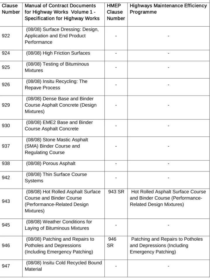
The table below lists the current Clauses from the Specification for Highways Works and alternate Clauses developed by the HMEP for local highways authority use. As noted above, in addition a range of standard detail drawings have been developed to cover the detailing of drainage works for local authority highway works.
6
Development of Standard Specification and Standard Details for Local Highway Maintenance Appendix 1 – Standard Specification and Notes for Guidance Version 1 - November 2012 Contents List
Series 500 – Specification for Highways Works to HMEP Comparison
Clause Number
Manual of Contract Documents for Highway Works Volume 1 - Specification for Highway Works HMEP Clause Number Highways Maintenance Efficiency Programme
501 (05/01) Pipes for Drainage and Service Ducts
501 SR Pipes for Drainage and Service Ducts
502 Excavation for Pipes and Chambers
502 SR Excavation for Pipes and Chambers
503 (11/05) Bedding, Laying and Surrounding of Pipes
503 SR Bedding, Laying and Surrounding of Pipes
504 Jointing of Pipes 504 SR Jointing of Pipes 505 Backfilling of Trenches and Filter
Drains
505 SR Backfilling of Trenches and Filter Drains
506 Connecting to Existing Drains
Chambers and Channels - -
507 (05/01) Chambers 507 SR Chambers
508 Gullies and Pipe Junctions 508 SR Gullies and Pipe Junctions 509 Testing and Cleaning 509 SR Testing and Cleaning 510 Surface Water Channels and
Drainage Channel Blocks
510 SR Surface Water Channels and Drainage Channel Blocks 511 Land Drains 511 SR Land Drains
512 Backfilling to Pipe Bays and Verges on Bridges
512 SR Backfilling to Pipe Bays and Verges on Bridges
513 Permeable Backing to Earth Retaining Structures
513 SR Permeable Backing to Earth Retaining Structures
514 Fin Drains 514 SR Fin Drains
515 Narrow Filter Drains 515 SR Narrow Filter Drains 516 Combined Drainage and Kerb
Systems
516 SR Combined Drainage and Kerb Systems
7
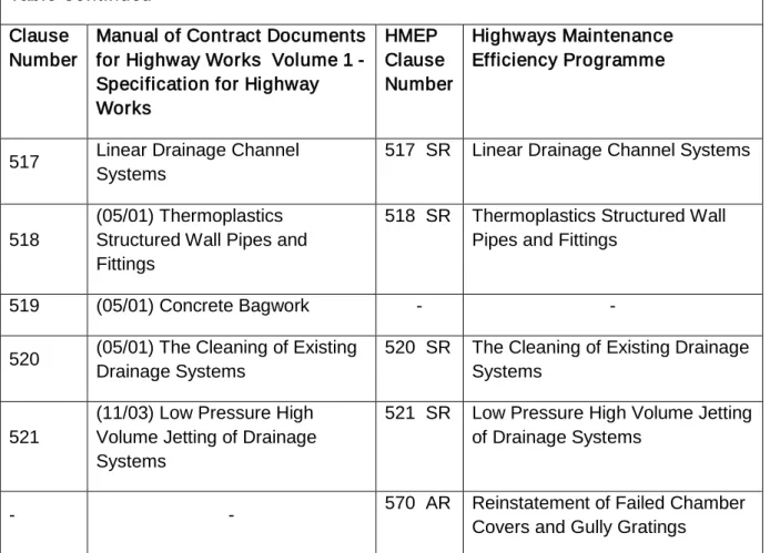
Development of Standard Specification and Standard Details for Local Highway Maintenance Appendix 1 – Standard Specification and Notes for Guidance Version 1 - November 2012 Table Continued
Clause Number
Manual of Contract Documents for Highway Works Volume 1 - Specification for Highway Works HMEP Clause Number Highways Maintenance Efficiency Programme
517 Linear Drainage Channel Systems
517 SR Linear Drainage Channel Systems
518
(05/01) Thermoplastics Structured Wall Pipes and Fittings
518 SR Thermoplastics Structured Wall Pipes and Fittings
519 (05/01) Concrete Bagwork - -
520 (05/01) The Cleaning of Existing Drainage Systems
520 SR The Cleaning of Existing Drainage Systems
521
(11/03) Low Pressure High Volume Jetting of Drainage Systems
521 SR Low Pressure High Volume Jetting of Drainage Systems
- - 570 AR Reinstatement of Failed Chamber
Covers and Gully Gratings
HMEP CL 501 SR - PIPES FOR DRAINAGE AND FOR SERVICE
DUCTS
General
1. Where the term drain is used in this Series it shall be deemed to include the terms sewer and piped culvert.
The Contractor shall design the piped culverts listed in Appendix 1/10 in accordance with the requirements of Clause 106.
Series 8000 (Manual of Contract Documents for Highway Works 5.8.2) applies to the installation by trenchless techniques of highway drainage, service ducts, sleeves and culverts with internal diameters up to and including 900 mm nominal internal diameter or width.
2. All drains constructed of pipes as well as piped culverts up to and including 900 mm internal diameter shall comply with this Series and any additional requirements in Appendix 5/1. Drains constructed using pipes exceeding 900 mm internal diameter as well as box and piped culverts shall comply with Series 2500. Unless otherwise
8
Development of Standard Specification and Standard Details for Local Highway Maintenance Appendix 1 – Standard Specification and Notes for Guidance Version 1 - November 2012 described in Appendix 5/1 only one type of pipe shall be used within any individual
drain or service duct between consecutive chambers. The Contractor shall ensure that plastic pipes are not subject to deterioration due to sunlight during the period Pipes for Drainage
3. Pipes for drainage shall be selected from the alternatives in Table 5/1 and shall comply with the standards and particular requirements therein. The Contractor shall show that the pipes selected have hydraulic flow capacity equal to that adopted in the hydraulic design of the system as described in Appendix 5/1. Pipes and fittings other than those included in Table 5/1 shall be permitted provided that they hold a current British Board of Agrément Roads and Bridges Certificate (or equivalent) stating that they are a suitable alternative for the usage specified in Table 5/1. On completion of the whole of the drainage works, the Contractor shall provide the Overseeing Organisation with a schedule showing details of all pipe types used, including quality, joints and name of manufacturer.
Corrugated Steel Pipes
4. Corrugated steel pipes shall be manufactured from either:
(i) Bolted segmental plate pipes complying with sub-Clause 6 of this Clause and having plate thicknesses as described in Appendix 5/1; or
(ii) Galvanized steel sheet suitable for lock seam fabrication complying with BS EN 10327 grade DX51D + Z600, or aluminium coated steel sheet complying with AASHTO specification M274-87(2004).
Corrugated steel pipes complying with (ii) above shall be manufactured from steel of minimum thickness 1.25 mm unless otherwise described in Appendix 5/1.
5. Where described in Appendix 5/1 corrugated steel pipes shall be provided with additional protection of hot applied bitumen complying with AASHTO specification M190-95(2000), or an equivalent coating system.
6. Bolted segmental plate pipes shall meet the following requirements:
(i) Steel for the plates shall comply with BS 1449 : Part 1.1, Grade 3 or Grade 4, Condition HR.
(ii) After forming, the depth of the corrugations shall be within a tolerance of ± 6% and the pitch of the corrugations within a tolerance of ± 4% of the nominal dimensions. Plates shall have a minimum lip of 45 mm beyond each end crest. Cut edges shall be free from notches, gouges, rust or burrs.
(iii) Bolts and nuts for connecting plates shall comply with BS EN ISO 4014, BS EN 4017 and BS EN ISO 4032, for BS EN ISO 898-1 and BS EN 20898-2, ISO 898-2 property class 8.8, nominal size M20; or with BS 4395: Part 2, nominal size M20; or with BS EN ISO 898-1 and BS EN 20898-2, ISO 898-2 property class 10.9.
9
Development of Standard Specification and Standard Details for Local Highway Maintenance Appendix 1 – Standard Specification and Notes for Guidance Version 1 - November 2012 (iv) When all the plates have been assembled, the nuts shall be tightened against
a domed washer. The tightening shall be repeated if necessary to achieve the torque recommended by the manufacturer.
(v) Steel plate shall be galvanized in compliance with Clause 1909. Plates shall be galvanized after forming the corrugations and completing all necessary cutting, punching and drilling. Units in which the zinc coating has been burned by welding or otherwise damaged in fabrication, transport or handling at Site shall be made good in compliance with Clauses 1907 and 1908. Bolts and nuts shall be galvanized in compliance with Clause 1909.
Table 5/1 SR – Pipes for Drainage
Material Usage Standard Particular Requirements
Vitrified clay Foul drains BS 65 or BS EN 295
“Normal” pipes as defined in BS 65
Surface water drains
BS 65 or BS EN 295
“Normal” or “surface water” pipes as defined in BS 65
Filter drains BS 65 BS EN 295
Unperforated, not exceeding 2.0 m in length with spigot and socket open joints
OR
Perforated with flexible mechanical joints Concrete (With Portland cement or sulphate-resisting cement when required in Appendix 5/1. Super-sulphated cement shall not be used)
Foul & surface water drains not exceeding 900 mm internal diameter BS 5911-1 and BS EN 1916 (Ordinary reinforced or unreinforced) BS 5911-5 Surface water drains not exceeding 900 mm internal diameter
BS 5911-110 For use with joints complying with sub-Clause 504.4
Filter drains BS 5911-114 (Porous with ogee or rebated joints)
10
Development of Standard Specification and Standard Details for Local Highway Maintenance Appendix 1 – Standard Specification and Notes for Guidance Version 1 - November 2012 Table 5/1 SR – Pipes for Drainage: continued
Material Usage Standard Particular Requirements
BS 5911-110 Unperforated not exceeding 2 m in length with open joints or castellated rebated joints with the total slot area between
castellations being at least 1000 mm2
OR
per metre length of pipe
Perforated with circular holes not greater than 10 mm nor less than 3 mm in diameter
Glass reinforced plastics (GRP)
Foul & surface water drains
BS 5480 Class to be as specified in Appendix 5/1
Iron Foul & surface water drains BS 437 (Cast iron) BS EN 598 (Ductile iron) Thermoplastics
solid wall pipes and fittings not exceeding 900 mm diameter Unplasticised polyvinyl-chloride (PVC-U) Polypropylene (PP) Polyethylene (PE)
Foul & surface water drains BS 4660 or BS 5481 or BS EN 1401 (PVC-U) BS EN 1852-1 (PP) BS EN 12666-1 (PE)
See the UK national guidance for the relevant BS EN. The grade appropriate for use without structural calculations shall be used i.e. SN8 for PP & PE and SN4 (SDR 41) for PVC-U Filter drains BS 4660 or BS 5481 or BS EN 1401 (PVC-U) BS EN 1852-1 (PP) BS EN 12666-1 (PE)
Perforated with not less than 1000 mm2 of holes per metre length of pipe. The perforations shall not reduce the pipe stiffness by more than 5%. Circular perforations not greater than 10 mm nor less than 3 mm in diameter or rectangular slots not greater than 4 mm nor less than 0.6 mm in width
11
Development of Standard Specification and Standard Details for Local Highway Maintenance Appendix 1 – Standard Specification and Notes for Guidance Version 1 - November 2012 Table 5/1 SR – Pipes for Drainage: continued
Material Usage Standard Particular Requirements
Thermoplastics structured wall pipe and fittings not exceeding 900 mm diameter
Surface water drains
Clause 518 Unperforated with watertight joints and with a pipe stiffness class, creep ratio and impact resistance as described in Appendix 5/1 Filter drains Clause 518 Perforated with not less than
1000 mm2 of holes per metre length of pipe. The perforations shall not reduce the pipe ring stiffness by more than 5%. Circular perforations neither greater than 10 mm nor less than 3 mm in diameter or rectangular slots neither greater than 4 mm nor less than 0.6 mm in width Subsoil field
drains
BS 4962 or Clause 518 Corrugated steel Surface water
drains, filter drains not exceeding 900 mm internal diameter AASHTO specification M36M-01 except as otherwise required in sub-Clauses 501.4, 5 and 6
All drains exceeding 900 mm internal diameter shall comply with Series 2500.
Pipes for Service Ducts
7. Pipes for service ducts shall be selected from the alternatives in Table 5/2 and shall comply with the standards and particular requirements therein. Pipes for other service ducts installed using trenchless methods shall conform to Series 8000 Manual of Contract Documents for Highway Works 5.8.2. Pipes for service ducts shall have a smooth internal bore without any sharp edges to the ends of pipes. They shall comply with any additional requirements described in Appendix 5/2, and be of 100 mm internal diameter unless otherwise described therein. Their alignment shall be tested in accordance with sub-Clause 509.9. The use of pipes and fittings other than those included in Table 5/2 shall be permitted provided that they hold a current British Board of Agrément Roads and Bridges Certificate (or equivalent) stating that they are a suitable alternative to those listed in Table 5/2.
8. Each duct shall be fitted with a pigmented, stranded polypropylene or equivalent rot-proof material draw rope of 5 kN breaking load and having a design life of not less
12
Development of Standard Specification and Standard Details for Local Highway Maintenance Appendix 1 – Standard Specification and Notes for Guidance Version 1 - November 2012 than 20 years, the ends of which shall be either made fast to marker blocks as shown
on HCD Drawing Number I1 or secured inside chambers. The ends of a duct shall be either sealed by removable stoppers immediately it has been laid, or terminated in chambers of the type specified in Appendix 5/2.
Table 5/2 SR – Pipes for Service Ducts
Material Standard Particular Requirements
Vitrified clay BS 65 or BS EN 295
Plain-ended, self-aligning flexible sleeve jointed with internal ends radiused to 3 mm minimum
Iron BS EN 598
(Ductile iron)
Glass reinforced plastics BS 5480 Class to be as specified in Appendix 5/2
Thermoplastics solid wall Unplasticised polyvinyl-chloride (PVC-U) Polypropylene (PP) Polyethylene (PE) BS 4660 or BS 5481 or BS 3506 (Class C) or BS EN 1401, BS EN 1452-1 to 5 as appropriate class PN10. BS EN 1852-1 (PP) BS EN 12666-1 (PE) When pipes BS 3506 (Class C) are used, joints shall comply with BS EN 1452-1 to 5 as appropriate
Thermoplastics single wall corrugated
(Restricted to ducts buried a minimum of 600 mm below the surface)
BS EN 50086-2-4 Ducts to BS EN 50086-2-4 shall be classified as normal duty, have a degree of protection against ingress of foreign objects classification rating of 3 or 4 and a degree of protection against ingress of water classification rating of 7. Appendix 5/2 shall state the resistance to bending requirements.
13
Development of Standard Specification and Standard Details for Local Highway Maintenance Appendix 1 – Standard Specification and Notes for Guidance Version 1 - November 2012 Table 5/2 SR – Pipes for Service Ducts: continued
Material Standard Particular Requirements
Thermoplastics structured wall BS EN 50086-2-4 and Clause 518 Ducts to BS EN 50086-2-4 shall be classified as normal duty, classification rating of 3 or 4 and a degree of protection against ingress of water classification rating of 7. Appendix 5/2 shall state the resistance to bending requirements.
HMEP NG 501 PIPES FOR DRAINAGE AND SERVICE DUCTS
1. Pipes can be made of materials that deflect relatively little under load before cracking (rigid pipes) or of materials that will tolerate large deflections under load before inward buckling occurs (flexible pipes). Flexible joints enable either type of pipe to take up differential settlement within the ground.
2. The Specification includes a wide range of pipe materials. The Contractor should normally be offered in Appendix 5/1 the full selection of alternative pipe and bedding combinations determined in accordance with Advice Note HA 40 (DMRB 4.2.5) as detailed in the HCD for pipes up to 900 mm internal diameter. The required pipe stiffness and impact resistance for plastics pipes should be specified in Appendix 5/1. The requirements for thermoplastics pipes and fittings will normally be as in Clause 518 with raw material and quality control requirements as in NG 518.
Piped culverts up to 900 mm internal diameter should be specified in Series 500. Drains, box culverts, piped culverts (and other drains) of clear span or internal diameter exceeding 900 mm are subject to the Overseeing Organisation’s technical approval and should comply with Series 2500. A box culvert should not be specified where either a (concrete) box culvert or a (corrugated steel) piped culvert would be technically acceptable. Wherever possible, the Contractor should be offered a choice and the Overseeing Organisation should be consulted during the scheme preparation. Box culverts, piped culverts (and other drains) of clear span or internal diameter exceeding 900 mm are structures subject to the Overseeing Organisation’s technical approval. Care should be taken to ensure that there are no inconsistencies between any specific requirements included in an outline Approval in Principle form and the general requirements of Series 500. Where necessary, Contract-specific amendments should be included in Appendix 0/1 or 0/2 to achieve consistency. Most of the pipes included in the Specification will normally be satisfactory from the hydraulic flow capacity factor. However some products, especially corrugated pipes, can
14
Development of Standard Specification and Standard Details for Local Highway Maintenance Appendix 1 – Standard Specification and Notes for Guidance Version 1 - November 2012 vary from the norm clay/ concrete and between manufacturers. The effect of a rougher pipe should be considered on the system as a whole and not just on the length in question. A pipe which is not acceptable on a straight exchange basis may be acceptable if diameters on adjacent lengths are adjusted. Appendix 5/1 should provide the basis on which the Contractor is to submit his proposals for pipe types and makes.
3. Any tendency to attack by acidic ground water or sulphates present in the backfill or the ground should be taken into account when the use of concrete, asbestos cement, steel or iron pipes is being considered for inclusion in the schedule of acceptable alternatives in Appendix 5/1.
The advice described in Clause NG 1704 should be considered regarding the risk of thaumasite sulphate attack on concrete used in drainage.
When acid soils (pH less than 6.5) are encountered, expert advice should be sought. There is some evidence that pipes made of sulphate-resisting cement and asbestos cement pipes will tolerate a pH as low as 6.0. The limiting value may be reduced to pH 5.5 when a bitumen coating is applied to the pipe. Sulphate attack on concrete is dealt with in Building Research Establishment Special Digest 1. Asbestos cement pipes will tolerate the same order of sulphates as concrete made from sulphate-resisting cement. More detailed information may be obtained from the manufacturers.
Protection to the lower third of the inside of corrugated steel piped culverts by means of an asphalt or insitu concrete coating will be required where stones and rocks are likely to be carried by the flow. Iron pipes are treated with a pitch or bitumen coating and have high durability in most soils, but when acid conditions are known to be present the additional protection of a polyethylene sleeve is desirable. Clay, GRP, pitch fibre and PVC-U pipes are resistant to a wide range of groundwater chemicals.
4. For corrugated steel pipes of lock seam fabrication with a diameter not exceeding 900 mm, the specification of metal thickness should be given in Appendix 5/1. The tables issued by manufacturers recommend thicknesses corresponding to the diameter and depth of fill above the pipe.
5. Pipes of more than one type within any individual drain or service duct between consecutive chambers will be exceptional. Whatever the circumstance giving rise to the proposal, consideration should be given to whether the joint between the two pipes will provide an appropriately watertight joint and a smooth inner transition for rodding purposes.
6. Plastics pipes may deteriorate after a long period in sunlight. Where pipes have been manufactured and stored before being delivered to the Site, it may be necessary for the Contractor to cover them until they are installed.
15
Development of Standard Specification and Standard Details for Local Highway Maintenance Appendix 1 – Standard Specification and Notes for Guidance Version 1 - November 2012 7. Any individual cable duct under a road may have to accept a power or a communication
cable although these are normally placed in separate ducts. Certain pipe materials have been excluded from the Specification for use as ducts because cables cannot be readily drawn through them. Clauses NG 518, NG 1421 and NG 1530 give further information on the use of ducts for electrical work. Ducts should be scheduled in a similar way to pipes in Appendix 5/2. Any special requirements of Statutory Undertakers etc. should be stated clearly.
8. Trenchless and minimum dig installation is the means of installing, replacing and renovating pipes, ducts and small tunnels with minimal or no excavation from the surface. Manual of Contract Documents for Highway Works 5, Series 8000 covers the requirements for trenchless and minimum dig installation of highway drainage, service ducts, sleeves and culverts up to and including 900 mm nominal internal diameter or width.
The information required from the designer/compiler that will detail the performance required from the trenchless installation should be given in NG Sample Appendix 80/1 (Manual of Contract Documents for Highway Works 5.8.3).
HMEP CL 502 SR - EXCAVATION FOR PIPES AND CHAMBERS
1. Excavation shall comply with Clause 602 and with the following:
(i) soft spots existing below the bottom of an excavation shall be removed and the resulting voids backfilled with Type 1 unbound mixture for sub base complying with Clause 803 or pipe bedding material complying with Clause 503, both well compacted, or ST1 concrete in compliance to Clause 2602; (ii) any additional excavation below the bottom of an excavation that is required
because the Contractor has allowed the bottom to become soft or otherwise unacceptable for the construction of the pipeline or chambers shall be made good as described in sub-Clause 1(i) of this Clause;
(iii) any excavation greater than the net volume required for the Permanent Works below the level of any pipe surround shall be made good as described in sub-Clause 1(i) of this sub-Clause.
2. Unless otherwise described in Appendix 5/1, all pipes in or under new embankments shall be laid only when the embankment has been formed and compacted to formation level under paved areas, to finished earthworks level in other areas, or to a level which will give a minimum cover of 1.2 m to the pipes, whichever is the lowest.
16
Development of Standard Specification and Standard Details for Local Highway Maintenance Appendix 1 – Standard Specification and Notes for Guidance Version 1 - November 2012
HMEP CL 503 SR - BEDDING, LAYING AND SURROUNDING OF
PIPES
1. Immediately following the excavation of the trench, the pipes shall be laid and jointed on the pipe bed. Pipes shall be laid so that each one is in contact with the bed throughout the length of its barrel. The pipes shall be laid at the level and gradients shown on the Drawings and schedules. The deviation in level from that specified at any point shall not exceed 20 mm and in addition the algebraic difference of the deviation in level at any two points on each pipe shall not exceed 30 mm. In the case of socketed or sleeve jointed pipes the bed shall be cut away and removed at each socket or sleeve to give a clearance of at least 50 mm, or 100 mm for trenches in material designated as Hard Material, so that the socket or sleeve does not bear on the bed. Pipes shall be laid on setting blocks only where a concrete bed or cradle is used.
Pipes and fittings shall be examined for damage and the joint surfaces and components shall be cleaned immediately before laying. Measures shall be taken to prevent soil or other material from entering pipes, and to anchor each pipe to prevent movement before the work is complete.
2. Pipes complying with BS 4962 : 1989 which are corrugated coilable perforated pipes shall, unless otherwise permitted in Appendix 5/1, be laid only by automatic single pass drain laying machines.
3. Drainage pipe and bedding combinations shall be selected from the alternatives described in Appendix 5/1. The granular material shall consist of natural and/or
HMEP NG 502 EXCAVATION FOR PIPES AND CHAMBERS
1. In the preparation of Appendix 6/3, it may be considered appropriate to permit battering of slopes where this would not affect adversely the Permanent Works or the basis of structural design of the pipe/ trench.
2. In the event of excavation to a greater depth than necessary the Contractor is obliged to reinstate. The use of ST1 concrete to remedy excess excavation should be restricted to areas where compaction is impracticable. Where the floor of the trench passes through a localised area of disturbed and uncompacted soil or softened clay further excavation and replacement with appropriate material may be required to allow pipe laying to proceed.
3. Where pipes are to be installed beneath heavily trafficked existing roads, etc, where it is undesirable that the existing ground surface should be disturbed, consideration should always be given to the possibility of inserting the pipe by suitable thrust boring or jacking processes.
17
Development of Standard Specification and Standard Details for Local Highway Maintenance Appendix 1 – Standard Specification and Notes for Guidance Version 1 - November 2012 recycled coarse aggregate or recycled concrete aggregate complying with BS EN
13242. Where recycled coarse aggregate or recycled concrete aggregate is used in this Clause, it shall have been tested in accordance with Clause 710 and shall not contain more than 1% other materials (Class X). Pipe bedding, haunching and surrounding material shall be as shown on HCD Drawing Numbers F1 and F2, and shall comply with the following:
(i) For pipes on beds shown on HCD Drawing Number F1 as Types B, F and S the aggregate shall have:
(a) geometrical requirements in accordance with Table 5/3; (b) a resistance to fragmentation in Category LA50
(c) a water-soluble sulphate content of less than 0.38% of sulphate (as SO3) when tested in accordance with BS EN 1744-1, clause 10;
in accordance with BS EN 13242, clause 5.2 and Table 9;
(d) all other requirements in Category NR
(ii) For pipes on beds shown on HCD Drawing Number F1 as Types N and T the aggregate shall comply with the geometrical requirements of either Table 5/3 or with Table 5/4, and with the fragmentation, water-soluble sulphate content and other requirements of (i) above.
.
TABLE 5/3: BS EN 13242, Coarse aggregate for pipe bedding, haunching and surrounding material
BS EN 13242, Coarse aggregate (clause 4.3.2) Category for general grading
requirements
GC80-20 Category for tolerances at mid-size
sieves
GTNR (no requirements) Category for maximum values of fines
content
Gravel – f
Crushed rock, recycled aggregate - f4 1.5
Nominal pipe diameter, mm Aggregate size, mm
Graded Single sized
Not exceeding 140 - 4/10
Exceeding 140 but not exceeding 400 2/14 or 4/20 4/10, 6/10 or 10/20
18
Development of Standard Specification and Standard Details for Local Highway Maintenance Appendix 1 – Standard Specification and Notes for Guidance Version 1 - November 2012 TABLE 5/4: BS EN 13242, Fine and all-in aggregated for pipe bedding, haunching and
surrounding material
BS EN 13242, Fine and all-in aggregate (clause 4.3.3)
Fine All-in
Category for general grading Category
requirements GF80
Category GA80 Category for tolerances on
manufacturer’s declared typical grading
GTF NR (no GT requirement)
A NR (no requirement) Category for maximum values of fines
content
Gravel – f
Crushed rock, recycled aggregate – f 3
11
Nominal pipe diameter, mm Aggregate size, mm
Fine All-in
Not exceeding 140 0/10
Exceeding 140 but not exceeding 400 0/1, 0/2, 0/4 or 0/6 0/10 or 0/20
Exceeding 400 0/10, 0/20 or 0/40
(iii) For pipes on beds shown on HCD Drawing Number F1 as Types A and Z concrete shall be ST4 and ST2, in compliance to Clause 2602, respectively. Backfilling shall not be carried out until after the concrete has cured.
(iv) Except for filter drains a further surround above the bed, haunch and surround described above shall be provided to a height of 300 mm above the top of the pipe consisting of Class 8 lower trench fill material as described in Table 6/1 and in compliance with Series 600.
(v) Unless otherwise described in Appendix 5/1 the materials used for the bedding, haunching and surrounding of filter drains shall comply with the appropriate bedding, haunching and surrounding materials specified in sub-Clauses 503.3.(i) to 503.3.(iv) and with the requirements for backfilling specified in sub-Clause 505.3.
4. Material for bedding, haunching and surrounding pipes shall not be deposited within 500 mm, or any other distances described in Appendix 5/1, of concrete, cement bound materials, other cementitious materials or stabilised capping forming part of the Permanent Works if, when tested in accordance with TRL Report 447 either:
(i) the water-soluble sulphate (WS) content exceeds 1500 mg of sulphate (as SO4
(ii) the oxidisable sulphate (OS) content exceeds 0.5% of sulphate (as SO ) per litre (Test No.1); or
4) (Test No.2 and Test No.4); or
19
Development of Standard Specification and Standard Details for Local Highway Maintenance Appendix 1 – Standard Specification and Notes for Guidance Version 1 - November 2012 (iii) the 2:1 water to soil extract prepared for the determination of water-soluble
sulphate in (i) has a pH value of less than 7.2, when tested using the electrometric method of pH determination in accordance with BS 1377-3. At least five samples of each material shall be tested for WS, OS and pH value. The mean of the highest two values shall be used for comparison with the limiting values. This also applies if six to nine results are available. If ten or more results are available, the mean of the highest 20% of the results shall be used for comparison with the limiting values.
5. Material for bedding, haunching and surrounding pipes shall not be deposited within 500 mm, or any other distances described in Appendix 5/1, of metallic structural elements forming part of the Permanent Works if, when tested in accordance with TRL Report 447 either:
(i) the water-soluble sulphate (WS) content exceeds 300 mg of sulphate (as SO4
(ii) the oxidisable sulphides (OS) content exceeds 0.06% of sulphate (as SO ) per litre (Test No.1); or
4
At least five samples of each material shall be tested for WS and OS. The mean of the highest two values shall be used for comparison with the limiting values. This also applies if six to nine results are available. If ten or more results are available, the mean of the highest 20% of the results shall be used for comparison with the limiting values.
) (Test No.2 and Test No.4).
The requirements in (i) and (ii) above shall not apply to metallic items protected by concrete and ancillary metallic items such as the tops of chambers and gullies.
6. Except where the pipeline is to be tested in compliance with Clause 509 before backfilling, the completion of the bedding, haunching and surrounding of the pipes is to be carried out immediately after jointing. The bed, haunch and surround shall be brought up equally on both sides of the pipe ensuring that it is in contact with the underside of the pipe barrel and be carefully compacted in layers not exceeding 150 mm thickness ensuring full compaction next to the trench walls. Pipes shall be maintained to line and level during the bedding, haunching and surrounding operations. Where pipelines are to be tested before being covered the bedding haunching and surrounding material shall only be brought up sufficiently to support the pipeline and the joints shall be left exposed until the test is completed satisfactorily. 7. Duct construction shall comply with the requirements of Appendix 5/2.
20
Development of Standard Specification and Standard Details for Local Highway Maintenance Appendix 1 – Standard Specification and Notes for Guidance Version 1 - November 2012
HMEP NG 503 BEDDING, LAYING AND SURROUNDING OF
PIPES
1. Pipe bedding material should be readily obtainable since a wide range of gradings and sizes complying with BS EN 13242 are permitted. Pipe bedding material needs to flow readily and compact uniformly, thus a low coefficient of uniformity is necessary. In order to make savings in coarser granular materials a sand bed may be adopted. Surround to pipes should be in bedding material or acceptable material (Class 8) as appropriate to the alternatives shown in the HCD. Coarse granular material may consist of natural aggregate, recycled coarse aggregate, recycled concrete aggregate, artificial or blended combinations of these aggregates, which satisfy the requirements of the specification.
2. The limiting values in sub-Clauses 503.4 and 503.5 have been chosen to ensure that problems do not occur due to oxidation of reduced sulphur compounds such as pyrite. Further guidance is given in sub-Clause NG 601.8 and Clause NG 644.
3. A distinction is to be made between the requirements of bedding, haunching and surrounding and those of backfilling. The former comprise all operations of trench fill up to a level 300 mm above the top of the barrel of the pipe. Backfilling constitutes the remaining operations up to ground level in verges and open ground and up to formation or sub-formation level under carriageways. Work above formation level constitutes construction or reinstatement of the pavement (see NG 706).
4. Concrete surround should be used exceptionally, e.g. for protection of pipes against mechanical damage from subsequent operations after construction of the pipeline and where remedial measures due to over excavation are required. Protection of existing pipes where necessary may take the form of a concrete arch or slab above the pipe.
21
Development of Standard Specification and Standard Details for Local Highway Maintenance Appendix 1 – Standard Specification and Notes for Guidance Version 1 - November 2012
HMEP CL 504 SR - JOINTING OF PIPES
1. Rigid joints shall mean joints made solid by caulking the sockets, or bolting together flanges integral with the pipes. Flexible joints shall mean joints made with deformable rings or gaskets held between pipe spigots and sockets, sleeves or collars.
2. Joints in surface water drains shall be watertight complying with sub-Clause 3 of this Clause or partly watertight complying with sub-Clause 4 of this Clause as described in Appendix 5/1. Foul drains shall have watertight joints. Filter drains shall have joints complying with sub-Clause 6 of this Clause. Ducts need not have watertight joints unless otherwise described in Appendix 5/2.
3. Watertight joints shall comply with the appropriate British Standards, the manufacturer’s instructions and the following:
(i) Rigid joints shall be used only where permitted in Appendix 5/1. Spigots and sockets of rigid joints may be caulked with tarred rope yarn or equivalent and the socket completely filled with mortar designation (i) complying with Clause 2404, excluding lime; a fillet of mortar being worked around the socket extending for a length of not less than 50 mm from the face of the socket. Iron pipes with open sockets shall have rigid joints caulked with lead wool or equivalent.
(ii) Joints in PVC-U pipes shall not be made with plastic solvent.
(iii) Flexible mechanical joints may be used with surface water pipes complying with BS 65.
(iv) Joints for cast iron pipes to BS 437 shall comply with BS EN 877.
(v) Joints in thermoplastics structured wall pipe shall comply with Clause 518. 4. Partly watertight joints for surface water drains shall be tested in accordance with
sub-Clause 509.7 and shall be British Standard joints or non-British Standard joints. Push fit joints shall have a register to ensure that the pipe is fully pushed into the joint.
Corrugated steel pipes of lock seam fabrication, not exceeding 900 mm internal diameter, shall be joined in accordance with the manufacturer’s instructions. Bolted segmental plate pipe arches or circular pipes, not exceeding 900 mm internal diameter, shall be joined in accordance with sub-Clause 501.6 (iv) and the manufacturer’s instructions.
5 Where a concrete bed, cradle, arch or surround is used with rigid pipes having flexible joints, joint filler board complying with Clause 1015 shall be placed in contact with the end of the socket at a pipe joint and shall extend through the full thickness of the concrete in contact with the pipe.
22
Development of Standard Specification and Standard Details for Local Highway Maintenance Appendix 1 – Standard Specification and Notes for Guidance Version 1 - November 2012 Such joints in the concrete bed, haunch or surround shall be at intervals not exceeding
5 metres except where the spacing of joints in the pipe exceeds 5 metres when they shall be at each pipe joint.
6. Joints in pipes for filter drains shall comply with the appropriate British Standard and with the following:
(i) Non-porous and unperforated concrete and clay pipes with spigot and socket, rebated or ogee joints shall be laid with unsealed joints and with a gap of 10 mm between the end of the pipe and the inner end of the socket or rebate. The pipes shall be supported with tarred rope yarn or equivalent flexible jointing material within the sockets over the lower third of the circumference so that there are no vertical steps between one pipe and another. Such pipes shall only be used with Type B filter material as described in Clause 505. (ii) The ends of perforated, castellated or porous concrete pipes with rebated
joints and perforated clay ware pipes with rebated or with flexible sleeve joints shall be pushed tightly together. The width of slots measured along the length of the pipeline formed by jointing castellated pipes shall not exceed 10 mm.
(iii) Perforated or slotted thermoplastics pipes with spigots and sockets or sleeves may be dry-jointed or jointed as described in sub-Clauses 3 and 4 of this Clause.
(iv) Other perforated pipes shall be jointed as unperforated pipes of the same material.
7. Joints in pipes for service ducts shall comply with the appropriate British Standard and with the following:
(i) Pipes for ducts shall be jointed so that no silt, grit, grout or concrete surround is able to enter the duct. Pipes with push-fit joints shall have a register to ensure that the pipe is fully pushed into the joint.
(ii) Joints in pipes to BS 3506 shall comply with BS EN 1452-1 to 5 as appropriate.
23
Development of Standard Specification and Standard Details for Local Highway Maintenance Appendix 1 – Standard Specification and Notes for Guidance Version 1 - November 2012
HMEP NG 504 JOINTING OF PIPES
1. Pipe joints for surface water drains, unlike foul drains, do not always have to be completely watertight. Small amounts of seepage as allowed in sub-Clause 509.7 can be tolerated particularly where pipes are laid in cuttings or below the water table. However, joints in pipes in soils that are predominantly fine sands or coarse silts should have watertight joints to prevent soil particles passing through the joint into the pipe leaving voids on the outside of the pipe.
Where fine sands or coarse silts might be a problem but the more expensive rubber ring flexible joint is unwarranted, consideration can be given to certain proprietary wrap type joints that are available. These may also be specified where root penetration needs to be prevented. Requirements should be given in Appendix 5/1. 2. Most watertight joints will be flexible joints although rigid joints are occasionally used
on clay pipes. In and under embankments, or if differential settlement is expected in compressible soils subject to non-uniform loading, then flexible joints and (except for pipes below the water table laid in non-erodible soils) watertight joints should be specified. The maximum length of pipe between flexible joints may have to be limited where considerable movement is expected. The limits of the exclusions should be shown in Appendix 5/1.
3. Culverts are generally considered to be drains but they do not necessarily require watertight joints. Where watertight joints are required for culverts this should be stated in Appendix 5/1.
4 Where seepage occurs from surface water pipes it will drain naturally through the pipe bedding materials and may be collected by means of a weep pipe placed at the down stream manhole.
HMEP CL 505 SR - BACKFILLING OF TRENCHES AND FILTER
DRAINS
1. Backfilling shall be undertaken immediately after the required operations preceding it have been completed.
2. Except where otherwise described in Appendix 5/1, trenches other than filter drain trenches shall be backfilled above the pipe surround material described in Clause 503, with Class 1, 2, or 3 general fill material complying with Series 600.
3. Filter drains shall be backfilled as described in Appendix 5/1 with Type A, Type B or Type C filter material which shall consist of natural or recycled coarse aggregate or recycled concrete aggregate complying with BS EN 13242 and the following:
(i) for Type A and C, grading requirements for unbound mixtures in accordance with Table 5/5 and BS EN 13285;
24
Development of Standard Specification and Standard Details for Local Highway Maintenance Appendix 1 – Standard Specification and Notes for Guidance Version 1 - November 2012 (ii) for Type B, geometrical requirements in accordance with Table 5/5 and BS
EN 13242;
(iii) a resistance to fragmentation in Category LA50
(iv) a water-soluble sulphate content of less than 0.38% of sulphate (as SO in accordance with BS EN 13242, clause 5.2 and Table 9;
3
(v) all other requirements in Category
) when tested in accordance with BS EN 1744-1, clause 10;
NR
(vi) be non-plastic when tested in accordance with BS 1377 : Part 2. ;
Where recycled coarse aggregate or recycled concrete aggregate is used in accordance with this Clause, it shall have been tested in accordance with Clause 710 and shall not contain more than 1% other materials (Class X).
Table 5/5: Grading and geometrical requirements for filter drain material
Type A Type B Type C
Standard BS EN 13285 BS EN 13242 BS EN 13285 Size, mm 0/20 20/40 As described in Appendix 5/1 Grading and oversize categories GF (with an G additional sieve) C 80-20 Oversize category OC80 - Category for tolerances at mid-size sieves - GTNR (no requirement) Category for maximum fines UF3 fNR (no requirement) Summary grading requirements
Sieve size, mm Percentage by mass passing 80 63 40 20 10 - - 100 80 – 99 50 – 90 100 98 – 100 80 – 99 0 – 20 0 – 5 As described in Appendix 5/1
25
Development of Standard Specification and Standard Details for Local Highway Maintenance Appendix 1 – Standard Specification and Notes for Guidance Version 1 - November 2012 Table 5/5: Grading and geometrical requirements for filter drain material:
continued
Sieve size, mm Percentage by mass passing 4 2 0.500 0.125 0.063 30 – 75 15 – 60 0 – 35 0 – 4 0 - 3 - - - - - As described in Appendix 5/1 % in size fraction 4/10 5 - 35 - 2/4 5 - 35 -
Filter materials, when tested in accordance with sub-Clause 509.8 shall have permeability requirements as described in Appendix 5/1.
When Type A material is used with pipes other than porous pipes at least 15% of the material shall be larger than the diameter of hole or larger than 1.2 times the width of slot in the pipe.
4. Material for backfilling trenches and filter drains shall not be deposited within 500 mm, or any other distances described in Appendix 5/1, of concrete, bound materials, other cementitious materials or stabilised capping forming part of the Permanent Works if, when tested in accordance with TRL Report 447 either:
(i) the water-soluble sulphate (WS) content exceeds 1500 mg of sulphate (as SO4
(ii) the oxidisable sulphate (OS) content exceeds 0.5% of sulphate (as SO ) per litre (Test No.1); or
4
(iii) the 2:1 water to soil extract prepared for the determination of water-soluble sulphate in (i) has a pH value of less than 7.2, when tested using the electrometric method of pH determination in accordance with BS 1377-3.
) (Test No.2 and Test No.4); or
At least five samples of each material shall be tested for WS, OS and pH value. The mean of the highest two values shall be used for comparison with the limiting values. This also applies if six to nine results are available. If ten or more results are available, the mean of the highest 20% of the results shall be used for comparison with the limiting values.
26
Development of Standard Specification and Standard Details for Local Highway Maintenance Appendix 1 – Standard Specification and Notes for Guidance Version 1 - November 2012 5. Material for backfilling trenches and filter drains shall not be deposited within 500 mm,
or any other distances described in Appendix 5/1, of metallic structural elements forming part of the Permanent Works if, when tested in accordance with TRL Report 447 either:
(i) the water-soluble sulphate (WS) content exceeds 300 mg of sulphate (as SO4
(ii) the oxidisable sulphate (OS) content exceeds 0.06% of sulphate (as SO ) per litre (Test No.1); or
4
At least five samples of each material shall be tested for WS and OS. The mean of the highest two values shall be used for comparison with the limiting values. This also applies if six to nine results are available. If ten or more results are available, the mean of the highest 20% of the results shall be used for comparison with the limiting values.
) (Test No.2 and Test No.4).
The requirements in (i) and (ii) above shall not apply to metallic structural elements protected by concrete and ancillary items such as the tops of chambers and gullies. 6. Backfilling shall be deposited and compacted in compliance with Clause 612. Filter
material for filter drains shall be deposited in layers not exceeding 225 mm loose depth; each layer then being compacted in compliance with Table 6/4 Method 3.
7. Material shall be deposited in even layers and shall not be heaped in the trench before being spread. Spreading and compaction shall be carried out evenly without dislodging, distorting or damaging the pipe. Power rammers shall not be used within 300 mm of any part of the pipe or joint.
8. Except in carriageways, other paved areas and locations described in Appendix 5/1, backfill of trenches shall be brought up to ground level. Where topsoil is at the surface on the line of the trench the upper section of the backfill shall be topsoil of the thickness described in Appendix 6/8, or of the same thickness and quality of topsoil as the surrounding ground where no thickness is specified. For trenches in carriageways or other paved areas the backfill shall be brought up to formation level, or sub-formation level where capping is required, unless a lower level is described in Appendix 5/1. Sheeting and other excavation supports shall be removed as the filling proceeds unless otherwise described in Appendix 6/3.
9. The position of service ducts shall be marked when the trenches are backfilled and permanent marker blocks and location posts provided as described in Appendix 5/2.