Linux
Software Developer's Kit (SDK)
User Guide
Part Number 900-548
Revision D March 2011
EDS1100/2100
Copyright & Trademark
© 2011 Lantronix. All rights reserved. No part of the contents of this book may be transmitted or reproduced in any form or by any means without the written permission of Lantronix. Printed in the United States of America.
Linux is a registered trademark of Linus Torvalds. µClinux is a registered trademark of Arcturus Networks Inc. Coldfire is a registered trademark of Freescale Semiconductor, Inc. Ubuntu is a registered trademark of Canonical Ltd. The Fedora trademark is a trademark of Red Hat, Inc.
Warranty
For details on the Lantronix warranty replacement policy, please go to our Web site at
Contacts
Lantronix Corporate Headquarters 167 Technology Irvine, CA 92618, USA Phone: 949-453-3995 Fax: 949-450-7249 Technical Support Online: Sales Offices
For a current list of our domestic and international sales offices, go to the Lantronix Web site at
Disclaimer
This product has been designed to comply with the limits for a Class B digital device pursuant to Part 15 of FCC and EN55022:1998 Rules when properly enclosed and grounded. These limits are designed to provide reasonable protection against radio interference in a residential
installation. This equipment generates, uses, and can radiate radio frequency energy, and if not installed and used in accordance with this guide, may cause interference to radio
communications.
The information in this guide may change without notice. The manufacturer assumes no responsibility for any errors that may appear in this guide.
For the latest revision of this product document, please check our online documentation at
Revision History
Date
Rev.
Comments
5/09 A Initial Document
9/09 B Updated for the XPort Pro support.
6/10 C Updated for SDK Version 2.0 and support for EDS 1100/2100 3/11 D Updated SDRAM information.
Contents
Copyright & Trademark ... 2
Warranty ... 2 Contacts ... 2 Disclaimer ... 2 Revision History ... 2 List of Figures ... 6 List of Tables ... 6
1.
Overview
8
Hardware Specifications ... 9 Software ... 9Terms and Abbreviations ... 10
2.
Installing the SDK
11
Host Requirements ... 11Linux Distributions ... 11
Host TFTP Server Configuration ... 14
CD Contents ... 15
Installation ... 16
Installed Directories ... 18
3.
dBUG Boot loader
19
Introduction ... 19Installing dBUG ... 19
Basic Configuration ... 21
Boot Failure Detection ... 23
Silent Boot Option ... 23
Restoring Ethernet Address ... 23
Dual Bank ... 23
dBUG Command Summary ... 24
dBUG Set Command Options ... 24
dbug-config Linux Utility ... 25
4.
Supported File Systems
27
Introduction ... 27 ROMFS ... 27 JFFS2 ... 28 NFS ... 295.
Flash Partitioning
32
Intro to Partitioning ... 32 Dual Bank ... 32Default Flash Memory Map for MatchPort AR, EDS1100, and EDS2100 ... 33
Default Flash Memory Map for XPort Pro ... 34
kernel + ROMFS root + blank JFFS2 ... 36
kernel + ROMFS root, preserving the JFFS2 partition ... 37
kernel + JFFS2 root ... 38
kernel + ROMFS root + JFFS2 + AUFS ... 39
Custom Layout ... 39
6.
Building µClinux
42
Configuration Profiles ... 42Kernel and Application Options ... 43
Building ... 46
7.
µClinux Startup Scripts
48
Introduction ... 48 etc/inittab ... 48 etc/init.d/rcS ... 48 etc/start ... 488.
µClinux Networking
49
Introduction ... 49 DHCP ... 49Static Address Configuration ... 49
DNS ... 49 inetd ... 50 telnetd ... 50 ftpd ... 50 dropbear ... 50 axhttpd ... 50
Contents ifconfig ... 50 mDNSResponder ... 50
9.
BusyBox
51
Intro to BusyBox ... 51 Enabling/Disabling Utilities ... 5110.
Sample Applications
54
Intro to Sample Applications ... 54s2e (Serial to Ethernet) ... 55
s2e-ssh ... 56
s2e-ssl ... 57
s2e-gpio ... 58
cpm (CP Manager) ... 59
LED ... 61
Check the Process Stack ... 61
Adding a New Application ... 62
11.
VIP Access Software
63
Introduction ... 63Enable VIP Access Software ... 63
Register the device on DSM ... 63
Bootstrap ... 63
Demo application ... 63
12.
Profiling & Debugging
66
Introduction ... 66gdbserver ... 66
syslog ... 66
iperf ... 67
Other Profiling and Debugging Utilities ... 67
13.
Firmware Updates
68
Introduction ... 68Firmware Updates by File System ... 68
Lantronix’ Sample Update Process Implementation ... 68
14.
Resources
72
Lantronix Open Linux SDK Forum ... 72Links to Related Web Sites ... 72
B.
Differences Between µClinux and Standard Linux
75
C.
Troubleshooting
76
Technical Support ... 76
List of Figures
Figure 2-1. Values ... 14Figure 3-1. DeviceInstaller Window ... 19
Figure 3-2. Firmware Upgrade Window ... 20
Figure 3-3. Serial Recovery Window ... 20
Figure 3-4. Serial Recovery Status Window Example for a MatchPort AR ... 21
Figure 3-5. Serial Recovery Results Window ... 21
Figure 3-6. dBug Configuration Window ... 22
Figure 3-7. Output from dbug-config program ... 25
Figure 5-1. Flash Layout – MatchPort AR, EDS1100, and EDS2100 ... 33
Figure 5-2. Flash Layout – XPort Pro ... 34
Figure 6-1. uClinux Kernel/Library/Defaults Window ... 43
Figure 6-2. uClinux Customize Application/Library Settings Window ... 44
Figure 6-3. uClinux Save Configurations Window ... 44
Figure 6-4. uClinux Save Configurations Window ... 45
Figure 6-5. uClinux Distribution Configuration Window ... 45
Figure 9-1. uClinux Distribution Configuration Window ... 51
Figure 9-2. uClinux Kernel/Library/Defaults Selection Window ... 52
Figure 9-3. uClinux Save Settings Window... 52
Figure 9-4. uClinux BusyBox Selection Window ... 53
Figure 9-5. uClinux BusyBox Configuration Window ... 53
Figure 10-1. Lantronix Applications Configuration Window ... 54
Figure 10-2. Serial-To-Ethernet Converter Screen ... 55
Figure 10-3. Serial-To-Ethernet Tunnel Setup Screen ... 55
Figure 10-4. Serial-To-Ethernet Tunnel Setup Screen with SSH ... 56
Figure 10-5. Serial-To-Ethernet SSH Setup Screen ... 56
Figure 10-6. Serial-To-Ethernet Tunnel Setup Screen with SSL ... 57
Figure 10-7. Serial-To-Ethernet SSL Setup Screen ... 58
Figure 10-8. Serial-To-Ethernet GPIO Setup Screen ... 59
Figure 10-9. CP Manager Interface Overview ... 61
Figure 11-1. Lantronix Applications Configuration Window ... 64
Contents
List of Tables
Table 1-1. Terms and Abbreviations ... 10
Table 2-1. CD Files ... 15
Table 2-2. Pre-built Images ... 16
Table 3-1. dBug Command Summary ... 24
Table 3-2. dBug Set Command Options ... 24
Table 6-1. Configuration Profiles ... 42
Table 12-1. Other Profiling and Debugging Utilities ... 67
Table A-1. Important Configuration Switches ... 73
1
1
.
.
O
O
v
v
e
e
r
r
v
v
i
i
e
e
w
w
The Lantronix Linux Software Developer's Kit (SDK) is an embedded hardware and software suite that enables Linux developers to create applications on Lantronix embedded networking modules. Detailed instructions for installing the SDK on your host Linux system are provided in this guide. It also describes the embedded module, its boot loader, flash partitioning schemes, and the build environment in detail. Information about many common embedded Linux utilities and configuration tasks is included. Sample programs, in addition to debugging and profiling tools, are provided and described in order to assist in the application development process.
1 Overview
Hardware Specifications
MatchPort AR
Memory:
RAM 8MB
FLASH 8MB Serial Interface:
Two COM ports (CON1 using console)
Max baud rate 230400 bps (default115200 bps)
Ethernet:
10/100 base TX with Auto Negotiation GPIO:
7 pinsXPort Pro
Memory:
SDRAM 8/16MB
FLASH 16MB Serial Interface:
One COM port
Max baud rate 921600 bps (default 115200 bps)
Ethernet:
10/100 base TX with Auto Negotiation GPIO:
3 pins(2 shared with serial driver)
EDS1100 Specs
Memory:
RAM 8MB
FLASH 8MB Serial Interface:
One COM port
Max baud rate 921600 bps (default 115200 bps)
Ethernet:
10/100 base TX with Auto NegotiationEDS2100 Specs
Memory:
RAM 8MB
FLASH 8MB Serial Interface:
Two COM ports(CON1 using console)
Max baud rate 921600 bps (default 115200 bps)
Ethernet:
10/100 base TX with Auto NegotiationSoftware
Boot loader: customized dBUG
OS: custom µClinux distribution
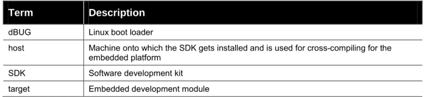
Terms and Abbreviations
Table 1-1. Terms and Abbreviations
Term
Description
dBUG Linux boot loaderhost Machine onto which the SDK gets installed and is used for cross-compiling for the embedded platform
SDK Software development kit target Embedded development module
2
2
.
.
I
I
n
n
s
s
t
t
a
a
l
l
l
l
i
i
n
n
g
g
t
t
h
h
e
e
S
S
D
D
K
K
Host Requirements
Please make sure that at least 2.5 GB of disk space are available before installation.
Root permissions are needed for very few operations. Please refer to the following section on ‘sudo Configuration’ for details.
Linux Distributions
This SDK was validated on these Linux distributions:
Redhat-based distributions
Fedora 9, 10, 11, 12, Fedora Core 5 & 6
CentOS 5.2, 5.3, 5.4
groupinstall 'Development Tools' (installs a lot of additional development tools not necessary for the SDK) or gcc, make, glibc-devel python sudo libacl-devel tftp-server or tftpd-hpa libtasn1-devel zlib-devel rsync
Optional but recommended packages
openssh, openssh-clients, openssh-server
nfs-utils
ncurses-devel (for the ncurses-based configuration utility)
libglade2-devel (for the GTK-based graphical configuration utility)
qt-devel (for the Qt3-based graphical configuration utility)
Debian-based distributions
Debian Lenny 5.0.2 & 5.0.4
Ubuntu 8.04, 8.10, 9.04, 9.10, 10.04
build-essential python sudo libacl1-dev tftpd or tftpd-hpa patch libtasn1-3-dev zlib1g-dev rsyncOptional but recommended packages
ssh
nfs-kernel-server
libncurses5-dev (for the ncurses-based configuration utility)
libglade2-dev (for the GTK-based graphical configuration utility)
libqt3-mt-dev (for the Qt3-based graphical configuration utility)
Other distributions
OpenSUSE 11.2
pattern install devel_C_C++
pattern install devel_kernel python sudo libacl-devel tftp or tftpd-hpa libtasn1-devel zlib-devel rsync
Optional but recommended packages
openssh, openssh-clients, openssh-server
nfs-utils
ncurses-devel (for the ncurses-based configuration utility)
libglade2-devel (for the GTK-based graphical configuration utility)
2 Installing the SDK
NOTE
If you are able to compile the Linux kernel on your host machine, you will also be able to build the SDK images. Lantronix highly recommends that the machine also act as an NFS-server.
sudo Configuration
Root permissions are needed for these operations that might need to be performed occasionally:
installation of additional packages on the host
configuring the TFTP- and NFS-servers
creating the target file system so it can be mounted via NFS
If you plan to use the NFS functionality then we recommend making sure that the sudo package is installed. Configure it so your user can run sudo [command] without having to provide root’s password. This can be achieved by adding an entry for your login (in the example below: sally) or for one of the groups you belong to (in the example below: adm) to /etc/sudoers. Beware that this might be considered a security risk in your organization.
A sample /etc/sudoers could look like this:
# /etc/sudoers #
# This file MUST be edited with the 'visudo' command as root. #
# See the man page for details on how to write a sudoers file. # Host alias specification
# User alias specification
# Cmnd alias specification
# Defaults
Defaults !lecture,tty_tickets,!fqdn
# User privilege specification root ALL=(ALL) ALL
sally ALL=(ALL) NOPASSWD: ALL
# Members of the admin group may gain root privileges %adm ALL=(ALL) NOPASSWD: ALL
Host TFTP Server Configuration
To transfer files from your host system to the target you may need to setup a TFTP server on your host machine. The following steps describe how to setup a TFTP server on a Fedora based distribution. The details of how to configure this server may vary among platforms. Consult your distribution’s documentation for further information.
To run the following commands as root or with sudo: 1. Install the tftp-server package (rpm)
yum install tftp-server
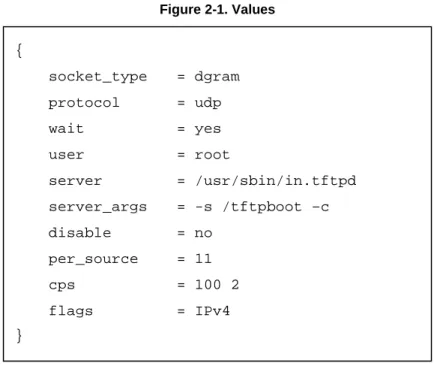
2. Edit /etc/xinetd.d/tftp and change the value of disable to “no”.
service tftp
Figure 2-1. Values
3. Restart the xinetd service.
service xinetd restart { socket_type = dgram protocol = udp wait = yes user = root server = /usr/sbin/in.tftpd server_args = -s /tftpboot –c disable = no per_source = 11 cps = 100 2 flags = IPv4 }
2 Installing the SDK
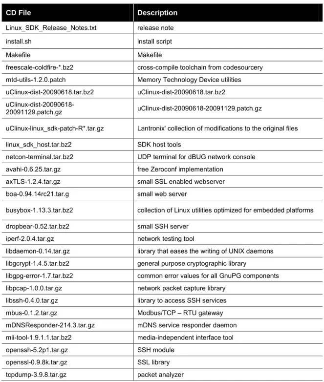
CD Contents
Files
Below is a brief description of the files on the CD. Filenames printed in italic are unmodified. All necessary modifications Lantronix has made to make them run better under the µClinux environment are in uClinux-linux_sdk-patch-R*.tar.gz.
Table 2-1. CD Files
CD File Description
Linux_SDK_Release_Notes.txt release note install.sh install script
Makefile Makefile
freescale-coldfire-*.bz2 cross-compile toolchain from codesourcery mtd-utils-1.2.0.patch Memory Technology Device utilities uClinux-dist-20090618.tar.bz2 uClinux-dist-20090618.tar.bz2
uClinux-dist-20090618-20091129.patch.gz uClinux-dist-20090618-20091129.patch.gz
uClinux-linux_sdk-patch-R*.tar.gz Lantronix' collection of modifications to the original files linux_sdk_host.tar.bz2 SDK host tools
netcon-terminal.tar.bz2 UDP terminal for dBUG network console avahi-0.6.25.tar.gz free Zeroconf implementation
axTLS-1.2.4.tar.gz small SSL enabled webserver boa-0.94.14rc21.tar.g small web server
busybox-1.13.3.tar.bz2 collection of Linux utilities optimized for embedded platforms dropbear-0.52.tar.bz2 small SSH server
iperf-2.0.4.tar.gz network testing tool
libdaemon-0.14.tar.gz library that eases the writing of UNIX daemons libgcrypt-1.4.5.tar.bz2 general purpose cryptographic library
libgpg-error-1.7.tar.bz2 common error values for all GnuPG components libpcap-1.0.0.tar.gz network packet capture library
libssh-0.4.0.tar.gz library to access SSH services mbus-0.1.2.tar.gz Modbus/TCP – RTU gateway mDNSResponder-214.3.tar.gz mDNS service responder daemon mii-tool-1.9.1.1.tar.bz2 media-independent interface tool openssh-5.2p1.tar.gz SSH module
openssl-0.9.8k.tar.gz SSL library tcpdump-3.9.8.tar.gz packet analyzer
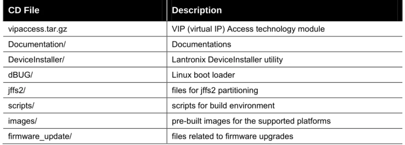
CD File Description
vipaccess.tar.gz VIP (virtual IP) Access technology module Documentation/ Documentations
DeviceInstaller/ Lantronix DeviceInstaller utility
dBUG/ Linux boot loader
jffs2/ files for jffs2 partitioning scripts/ scripts for build environment
images/ pre-built images for the supported platforms firmware_update/ files related to firmware upgrades
Pre-built Images
For each supported platform there are 6 pre-built images in <cdrom directory>/images/<platform>.
Table 2-2. Pre-built Images
Image Description
linux.bin Linux kernel This is just the Linux kernel. linuz.bin Compressed Linux kernel This is gzip compressed linux.bin
linux.without_header linux.bin without header This is for dBUG of Linux SDK 1.0.0.5 or before. romfs.img romfs image This is just the romfs image.
image.bin Linux kernel + romfs. Linux kernel and romfs image
imagez.bin Compressed Linux kernel + romfs. This is gzip compressed image.bin
image.without_header image.bin without header This is for dBUG of Linux SDK 1.0.0.5 or before. rootfs.img
JFFS2 image (full image).
This is JFFS2 root filesystem image that built user application directory. It's assumed that this is used without romfs (use linux.bin for kernel).
imageu.bin Compressed Linux Kernel + uncompressed romfs
Copy these files to your TFTP server directory.(e.g. '/tftpboot/')
Installation
To install software on your host machine:
2 Installing the SDK
$ mount | grep iso9660
If you see a line similar to:
/dev/hdc on /media/CDROM type iso9660 (ro,nosuid,nodev,uid=500)
Then the CD is already mounted. Please pay attention to the highlighted options in the brackets behind type iso9660. If it contains noexec, you have to issue the following command to allow the execution of scripts directly from the CD:
$ sudo mount -o remount -o exec /media/CDROM
3. Validate that the noexec flag is gone with:
$ mount | grep iso9660
If you forget this step you will get an error message like:
bash: /media/CDROM/install.sh: /bin/sh: bad interpreter: Permission denied
If you have access to the ISO image of the installation CD, then you can mount the ISO file directly with:
$ sudo mount -o loop <iso image>.iso <cdrom directory>
If you only have the CD use:
$ sudo mount -rt isofs9660 /dev/cdrom <cdrom directory>
4. Choose an <install directory> wherever you want and have write access to. This will also be your development directory.
$ cd <install directory>
$ <cdrom directory>/install.sh
If you run into an error message like this:
bash: /media/CDROM/install.sh: /bin/sh: bad interpreter: Permission denied
Then your media was mounted with the noexec option. Please check the previous paragraph carefully about mounting the installation CD.
5. Verify that the following message appears, which indicates that everything is working fine:
Install directory [<install directory>] ? (Y/n) : Y
6. Specify the full path to the <cdrom directory>.
If you see the questions, do the following:
You are using /bin/sh -> dash.
To use Linux SDK, you cannot use /bin/sh -> dash.
Attempt to automatically relink /bin/sh -> bash? (y/N): y
Missing needed host development packages.
Note that sudo privileges are required for installation. Attempt to automatically install missing packages? (y/N): y
After the installation your directory structure should look as described in the following section, Installed Directories
Installed Directories
<install directory> |
|- dBUG/ boot loader binary |- Documentation/ documents |- host/ host tools
|- hostsrc/ source code for host tools |
|- linux/ µClinux directory
| |- images/ kernel, romfs, and jffs2 images | |- linux-2.6.x/ Linux kernel
| |- uClibc C library | |- user Applications
| |- lantronix Lantronix applications |
|- pre-built-images/ pre built images |- toolchains/ toolchains directory |- Makefile Makefile
3
3
.
.
d
d
B
B
U
U
G
G
B
B
o
o
o
o
t
t
l
l
o
o
a
a
d
d
e
e
r
r
Introduction
Linux on the supported platform (MatchPort AR, XPort Pro, or EDS1100 / 2100) is loaded through two boot loader stages. The first stage is the Lantronix boot loader, which is present on both the Evolution OS and Linux based products. The Lantronix boot loader is marked as read-only, so it cannot be overwritten accidentally. The second stage is the dBUG boot loader, which is
responsible for loading Linux. It also contains options for downloading and flashing new kernel and filesystem images. This section describes dBUG in more detail.
Installing dBUG
The dBUG boot loader comes pre-installed with the Linux development kits. Replacing the boot loader image should not be necessary, but instructions for doing so are given below.
1. Connect an RS232 cable between a Windows PC COM Port (e.g. COM1 for the following steps) and one of serial ports on the target device e.g. MatchPort AR (CON1 on the eval board), XPort Pro (Port A on the demo board), EDS1100 (Serial), or EDS2100 (Serial 1). Close any existing software connections to COM1.
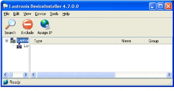
2. Run the Lantronix DeviceInstaller Utility on the Windows computer. The most recent version at the time of publication is provided on the installation CD for your convenience under DeviceInstaller/. The latest version can be downloaded from our Web site:
Figure 3-1. DeviceInstaller Window
3. From the Tools menu, select Advanced, then Recover Firmware. 4. Set the Port on PC to COM1.
5. Set the Device Model to match your embedded module (MatchPort AR, XPort Pro, or EDS1100/2100).
6. Click Browse to select the path to the dBUG image file. For example, the path for the MatchPort AR would be:
c:\install directory>/dBUG/dbug-R<ver>.romz
Figure 3-2. Firmware Upgrade Window
7. Click OK and follow the prompts for power cycling the target.
Figure 3-3. Serial Recovery Window
3 dBUG Boot loader
Figure 3-4. Serial Recovery Status Window Example for a MatchPort AR
8. Click OK when prompted. The dBUG boot loader should now be installed on the target.
Figure 3-5. Serial Recovery Results Window
Basic Configuration
1. Connect an RS232 cable between your host computer COM1 and any of the MatchPort AR (CON1 on the eval board), XPort Pro (Port A on the demo board), EDS1100 (Serial), or EDS2100 (Serial 1). Serial port settings are as follows:
baud rate: 115200 data length: 8 parity: None stop bit: 1
flow control: None
2. Turn on the target.
4. At the dBUG> console prompt, configure the dBUG settings. Use the following instructions for
configuring dBUG to boot an image containing the kernel and a ROMFS root file system over the network.
NOTE
A TFTP server with the image.bin file must be configured on the server with the specified address.
dBUG> set watchdog off dBUG> set base hex dBUG> set baud 115200 dBUG> set autoboot net
dBUG> set server <TFTP server address(e.g. 192.168.0.10)> dBUG> set client <target IP address(e.g. 192.168.0.1)> dBUG> set gateway <gateway address(e.g. 0.0.0.0)> dBUG> set netmask <network mask(e.g. 255.255.255.0]> dBUG> set filename image.bin
dBUG> set filetype image dBUG> set ethaddr default
dBUG> set dns <DNS server address(e.g. 0.0.0.0)> dBUG> set kcl rootfstype=romfs
5. Display the dBUG configuration using the ‘show’ command.
3 dBUG Boot loader 6. Issue a 'reset' at the dBUG prompt for the changes to take effect. Repeat step 3 to get back
to the dBUG prompt.
7. Clear the flash space for the JFFS2 partition using the ‘fl e’ command. The command below erases 4MB of flash starting at address 0x00400000. This can be mounted as a JFFS2 partition from Linux.
For the MatchPort AR or EDS1100 / 2100
dBUG> fl e 0x00400000 0x00400000
For the XPort Pro
dBUG> fl e 0x00400000 0x00C00000
8. Download the firmware image with ‘dn’ and boot Linux using the ‘go’ command. The target should now boot Linux via TFTP.
dBUG>dn dBUG>go
Boot Failure Detection
When enabled, the dBUG boot failure counter (bootfc) parameter is incremented each time dBUG starts booting, and reset from within Linux after a successful boot. When Linux fails to boot successfully, bootfc will increment each boot. When bootfc reaches maxbootfc dBUG will stop trying to boot Linux, and will await manual recovery. To enable the boot failure counter, set the maxbootfc parameter to the desired numeric value. Set maxbootfc to 0 or ‘off’ to disable the boot failure counter.
Silent Boot Option
The dBUG silent boot option disables both the display of dBUG boot messages, and the autoboot countdown. To enable the silent booting perform the following:
dBUG> set silentboot on
When silent boot mode is enabled, it is still possible to break into the dBUG command line. To do so, reset the target unit by cycling the unit's power (turning the power off and back on).
Immediately upon resetting the device, enter three ^x (Ctrl+x) characters.
Restoring Ethernet Address
To reset the Ethernet address used by dBUG and Linux back to the factory default setting, perform the following:
dBUG> set ethaddr defaults
Dual Bank
When dual bank is disabled, Linux can use the entire flash memory for the kernel and root file system.
When dual bank is enabled, flash is divided into two banks. Linux boots using a bank and keeps another bank unused. The second bank is used automatically during a firmware upgrade and provides redundant flash storage space that is useful in recovery scenarios when firmware upgrade fails. For more information about Flash mapping, see Chapter 5 Flash Partitioning.
To use dual bank: 1. Disable dual bank.
dBUG> set bootbank single
2. Enable dual bank and use bank 1 as boot bank.
dBUG> set bootbank 1
3. Enable dual bank and use bank 2 as boot bank.
dBUG> set bootbank 2
dBUG Command Summary
Table 3-1. dBug Command Summary
Command Description
dnfl download and write a kernel containing image file to flash dn download an image file into RAM
fl write ‘w’ or erase ‘e’ flash gfl boot from flash
go boot from RAM
help display available commands and their descriptions set set dBUG configuration option
show display dBUG configuration reset reset device
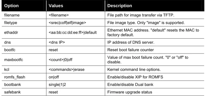
dBUG Set Command Options
Table 3-2. dBug Set Command Options
Option Values Description
watchdog on|off Enable/disable watchdog timer. silentboot on|off Enable/disable dBUG silent booting.
netcon on|off Enable/disable netcon (see Netcon section below) tftpsvr on|off Enable/disable TFTP server to allow firmware update pushes base hex|dec|bin|oct|unknown Radix of numerical arguments
baud 9600|19200|38400|… Serial baud rate.
autoboot stop|net|flash Boot source after reset, if any.
server <host IP> IP address of TFTP server to load image from. client <board IP> IP address to be used by target. "0.0.0.0" for BOOTP gateway <gateway IP> IP address of gateway (default router).
3 dBUG Boot loader
Option Values Description
filename <filename> File path for image transfer via TFTP. filetype <srec|coff|elf|image> File image type. Only "image" is supported. ethaddr <aa:bb:cc:dd:ee:ff>|default Ethernet MAC address. "default" resets the MAC to factory default. dns <dns IP> IP address of DNS server.
bootfc reset Reset boot failure counter
maxbootfc <count>|0|off Value of max boot failure count. "0" or "off" to disable. kcl <commands>|erase Kernel command line options.
romfs_flash on|off Enable/disable XIP for ROMFS bootbank single|1|2 Enable/disable Dual bank safebank reset Firmware upgrade status
dbug-config Linux Utility
The dbug-config program is a Linux utility for viewing and updating the dBUG configuration parameters. To display the current dBUG settings, run dbug-config with no arguments. To change settings run dbug-config with the setting name as the first argument and its new value as the second. Multiple attribute value pairs may be combined with the dbug-config command line. Values containing spaces must be enclosed within double quotes.
Netcon
The netcon network console program allows dBUG console access over the network. This is useful in situations where the device (MatchPort AR, XPort Pro, or EDS1100 / 2100) is remote, or when the console is otherwise unavailable. The path to the netcon client program in the SDK is
<install_directory>/host/usr/sbin/netcon.
By default the dBUG netcon server is active during the autoboot countdown and when the dBUG shell is active. This includes the failure recovery case where the max boot failure count has been triggered (if maxbootfc is enabled).
To connect to the dBUG netcon server:
4. Issue the following command on the host system.
$ netcon <target-ip>
5. Press Enter to get the dBUG prompt. If this does not work, it may be necessary to reset the target, and press enter repeatedly within the netcon client session until the dBUG prompt appears. The netcon program uses the connectionless UDP protocol, which makes it possible for a session to persist across target resets.
6. Press the ESC key to exit the netcon session.
Disabling netcon
In some situations it may be desirable to disable netcon access for security reasons. To disable netcon, issue the following command at the dBUG prompt.
dBUG> set netcon off
The change will take effect after the next reset. Use 'set netcon on' to re-enable netcon access.
Updating the Target IP Address with netcon
When the target's MAC address is known and its IP address is unknown, it is possible to update the target's IP address using netcon. Note that the host system must be on the same subnet as the target for this to work. The procedure for doing this is given below.
1. Set a static arp entry on the host, associating it's MAC address with the new IP address. Note that the arp syntax may differ depending on the platform. Consult the arp man page on your host machine for the exact syntax
$ /sbin/arp -s <new-IP> <target-MAC-address>
2. Start the netcon client.
$ netcon <new-IP>
3. Power on the target and press the Enter key repeatedly within the netcon client session. Once the dBUG prompt appears, the IP address will have been updated. Note that the updated IP will be lost upon a reset unless the 'set client <target-IP>' command is executed to write the new value to flash.
4
4
.
.
S
S
u
u
p
p
p
p
o
o
r
r
t
t
e
e
d
d
F
F
i
i
l
l
e
e
S
S
y
y
s
s
t
t
e
e
m
m
s
s
Introduction
Linux supports a wide range of file systems. Most of them were created with certain
characteristics in mind: high performance, reliability, compatibility with other operating systems, general purpose, etc.
Raw flash devices have inherently different characteristics than block devices such as hard drives and USB flash drives:
Flash areas have to get explicitly erased before they can be overwritten
Erase blocks, the smallest entities that can be erased on a flash, are usually considerably larger then sectors on hard drives
Limited number of rewrites (memory wear)
To address these constraints numerous file systems for raw flash devices exist. Among the most popular are: ROMFS JFFS2 CRAMFS SQUASHFS
ROMFS and JFFS2 are supported in this SDK and described in detail below. Both CRAMFS and SQUASHFS are read-only file systems that support compression. They are not currently
supported in this SDK since they are not part of the standard Linux kernel as of version 2.6.30. It should be relatively straightforward for the adventurous to add support for them.
information about raw flash devices.
ROMFS
What Does ROMFS Offer
ROMFS is the default file system for the µClinux distribution. It is a read-only uncompressed file system with minimal overhead.
The boot loader copies or decompresses the Linux kernel and the ROMFS into RAM (if romfs_flash is disabled) before jumping into the kernel. This has a few implications:
Since the root file system and the kernel are in RAM they can be easily overwritten on the fly by the firmware update process (unless ROMFS is executed from flash fr).
Only applications that need to run all the time should be kept in ROMFS because everything consumes valuable RAM space.
This may compensate easily for the waste of RAM if multiple instances of an application run at the same time.
ROMFS being a read-only file system, makes it easy to guarantee its integrity during runtime. On the other hand, all variable data like configuration files that might need to be updated during runtime need to be stored on a separate file system.
All applications in ROMFS can be run with XIP: eXecute In Place (set romfs_flash to on in
dBug) – see
All applications in the distribution get compiled with the XIP flag set by default.
Configure the Boot Loader for ROMFS as Root Partition
To tell µClinux kernel to look for a ROMFS root file system, the kernel command line (kcl) has to be set accordingly. To validate this, boot the target into dBUG and issue the following:
dBUG> show watchdog: on silentboot: off romfs_flash: off bootbank: Single safebank: 0 netcon: on tftpsrv: on base: 16 baud: 115200
autoboot: Stop at prompt
server: 172.19.239.1 client: 172.19.239.77 gateway: 172.19.0.1 netmask: 255.255.0.0 filename: /tftpboot/image.bin filetype: Image ethaddr: 00:20:4A:80:8C:7E dns: 172.19.1.1 bootfc: 0 maxbootfc: off kcl: rootfstype=romfs
If kcl is not set to rootfstype=romfs it can be fixed by issuing the command dBUG> set kcl rootfstype=romfs
and the target will try to mount the ROMFS.
JFFS2
What Does JFFS2 Offer
JFFS2 is a sophisticated writeable log-structured file system that supports wear-leveling. JFFS2 does not support XIP. One disadvantage of having a JFFS2 root file system is that it is extremely difficult to upgrade the firmware from within Linux without sufficient flash space (see Chapter 13
Firmware Updates). At minimum, the configuration files should be stored in a separate file system
that does not get overwritten by a firmware update.
UBIFS, LogFS, and YAFFS are promising new file systems trying to become the heir to JFFS2. They attempt to resolve many of its shortcomings.
4 Supported File Systems
Configure the Boot Loader for JFFS2 as Root Partition
To tell µClinux kernel to look for a JFFS2 root file system, the kernel command line (kcl) has to be set accordingly. To validate this, boot the target into dBUG and issue the following command:
dBUG> show watchdog: on
...
kcl: rootfstype=romfs
If kcl is not set to “noinitrd rw rootfstype=jffs2 root=/dev/mtdblock5” it can be fixed by issuing the command
dBUG> set kcl noinitrd rw rootfstype=jffs2 root=/dev/mtdblock5
and the target will try to mount its root file system from the JFFS2 partition.
NFS
µClinux comes with support for mounting directories from a remote computer via NFS. This can be very useful in many scenarios:
To speed up development: mount the development directory on the target from the host to eliminate time consuming manual transfer of the compiled files via ftp or scp.
To save data permanently (e.g. for logging or backing up data to a server)
Be aware that most sample profiles provided by Lantronix do not include support for NFS to save precious RAM. Depending on the chosen profile, you might have to activate the relevant
configuration switches in the Linux kernel: CONFIG_NFS_FS CONFIG_NFS_V3 CONFIG_NFS_COMMON CONFIG_IP_PNP_DHCP (optional) CONFIG_IP_PNP_BOOTP (optional)
NFS as root File System – The Option for Development
Mounting the whole root file system via NFS can be a great time saver. Without it, a typical development cycle would look like this:
1. Make a minor change to an application. 2. Create a new firmware image.
3. Flash it to the device (MatchPort AR, XPort Pro, or EDS1100 / 2100). 4. Reboot.
5. Validate the changes.
Consequently the developer would waste productive time with tedious tasks. Thus, we
recommend using the NFS as a root file system during development and debugging. This allows the developer to try out the changes on the device as soon as they are compiled. If none of the core components (kernel and BusyBox) were modified, the target does not even have to be rebooted.
All details can be found in < install-dir>/linux/linux-2.6.x/Documentation/filesystems/nfsroot.txt
There are a few onetime steps involved to enable this mode as identified below:
µClinux kernel configuration
CONFIG_ROOT_NFS needs to be enabled in the kernel configuration. If a BOOTP or DHCP server
is available on your network you might want to enable CONFIG_IP_PNP_BOOTP or CONFIG_IP_PNP_DHCP as well.
dBUG Configuration
Within dBUG, the kernel command line kcl needs to be set for NFS.
You have 2 options: use a fixed IP address or enable DHCP or BOOTP in the kernel.
Static IP
For example, if one of the host network cards is configured with an IP of 192.168.3.1 and the SDK is installed under <install-dir>/, then the target IP should be 192.168.3.88. Set the kcl using the following command:
NOTE:
The following code must be entered as one line. dBUG> set kcl noinitrd rw root=/dev/nfs
ip=192.168.3.88:255.255.0.0:192.168.3.1:::eth0 nfsroot=192.168.3.1:<install-dir>/linux/nfs
Dynamic IP
If a DHCP server is running on host, it can be used by performing the following: 1. Enable CONFIG_IP_PNP_DHCP in the kernel.
2. Set kcl noinitrd rw root=/dev/nfs ip=bootp nfsroot=192.168.3.1:<install-dir>/linux/nfs
NOTE:
The preceding code must be entered as one line.
Host Configuration
In order for the build process to produce a file system that can be mounted via NFS, the
developer needs to manually create a directory named 'nfs' in <install-dir>. This is the trigger for the build process to create the NFS-mountable directory structure. The user will also need sudo permissions without having to provide a password as described in Chapter 2: Installing the SDK .
On the host machine, NFS server support needs to be installed and enabled. The
<install-dir> needs to be made accessible via NFS by explicitly exporting it. This can be
done with a line like
install-dir>/linux 192.168.0.0/255.255.0.0(rw, no_root_squash, anonuid=500,anongid=500,insecure,sync,no_subtree_check)
4 Supported File Systems You will need to adjust the IP address and the netmask to match your network configuration. The 500 in the example above should reflect your user id on the host system.
Don't forget to execute “sudo exportfs –av” after modifying /etc/exports. If you do this the first time, make sure that you can mount the exported file system on your host or a different machine on the same network before trying to boot your MatchPort from it.
Mounting NFS File Systems During Runtime
Client Side Prerequisites
In addition to the basic kernel support for NFS please ensure that the following two options are enabled in your build:
CONFIG_USER_BUSYBOX_FEATURE_MOUNT_NFS CONFIG_USER_PORTMAP_PORTMAP
The kernel configuration options CONFIG_IP_PNP_DHCP and CONFIG_IP_PNP_BOOTP are not
needed for this configuration.
portmap needs to run to support user space NFS mounting. Make sure that it is running or start it like this from the command line:
/ # portmap &
Consider including the portmap call in a startup script if needed regularly.
AUFS
AUFS is an implementation of the idea to support mounts of several file systems into one single mount point, one overlaying each other. This might be used to cleanly separate read-only data from variable data.
We included a snapshot of AUFS into the kernel for your convenience. To see how this can be utilized, refer to Chapter 5 Flash Partitioning.
5
5
.
.
F
F
l
l
a
a
s
s
h
h
P
P
a
a
r
r
t
t
i
i
t
t
i
i
o
o
n
n
i
i
n
n
g
g
Intro to Partitioning
The idea of partitioning is to optimize the usage of the available flash space to meet your requirements. A Linux file system encompasses many files with different characteristics. There are binaries and data files. Some of them are crucial for the operation of the system all the time, while some need to be available in certain conditions only. Most files do not need to (and must not) be modified, some files are important, but variable (e.g. persistent configuration files) and then there are temporary files like logs.
Linux supports these requirements by letting the user mount different file system types into one file system tree. Some of them were described in the previous chapter.
Ideally all crucial static files should reside on a compressed read-only file system, nice to have ones on a separate read-only file system so they can be updated independently, variable files on a compressed write-enabled file system, and volatile files on a RAM disk.
This luxury comes at a price:
Each supported file system type costs scarce RAM
Managing different file systems on one flash chip is not trivial - what do you do when file system sizes have to be adjusted to accommodate the space requirements of a new firmware version?
Depending on the requirements of your application you will have to make your choice between the various tradeoffs. To keep things reasonably simple, but still extensible, we went with a rather minimalist default flash layout.
Dual Bank
Flash Partitioning depends on the Dual Bank setting of dBUG (single|1|2).
When using flash in a single bank configuration, Linux can use the entire flash memory for kernel and root file system.
When using flash in a dual bank configuration, the flash space is divided into two banks. Linux boots using one bank and keeps another bank unused. The bootbank parameter of dBUG specifies the bank to be used.
5 Flash Partitioning
Default Flash Memory Map for MatchPort AR, EDS1100,
and EDS2100
The following figure shows the flash layout as it is hard-coded in the Linux kernel.
Figure 5-1. Flash Layout – MatchPort AR, EDS1100, and EDS2100
/dev/mtd0 (64K) Lantronix BootLoader
/dev/mtd1 (64K) Factory Unit Configuration (64K)
/dev/mtd5 (2 MB) JFFS2 User Space /dev/mtd4 (1.75 MB) dBUG Image Header (128 Bytes)
Linux Kernel + (Optional) ROMFS
/dev/mtd8 (64K) dBUG Configuration Backup /dev/mtd3 (64K)
dBUG Configuration
/dev/mtd7 (192 KB) User Extra Space /dev/mtd2 (64K)
dBUG (Secondary Bootloader)
/dev/mtd5 (4 MB) JFFS2 User Space
Flash Layout – MatchPort AR, EDS1100, EDS2100
Single Bank Dual Bank – Bank 1 Dual Bank – Bank 2
/dev/mtd4 (3.75 MB) dBUG Image Header (128 Bytes)
Linux Kernel + (Optional) ROMFS 0x00000000 0x00040000 0x00030000 0x00020000 0x00010000 0x00200000 0x00400000 0x00440000
Reserved (Dual Bank Use)
0x00800000
/dev/mtd0 (64K) Lantronix BootLoader
/dev/mtd1 (64K) Factory Unit Configuration (64K)
/dev/mtd2 (64K) dBUG (Secondary Bootloader)
/dev/mtd3 (64K) dBUG Configuration
/dev/mtd8 (64K) dBUG Configuration Backup
/dev/mtd7 (192 KB) User Extra Space
/dev/mtd0 (64K) Lantronix BootLoader
/dev/mtd1 (64K) Factory Unit Configuration (64K)
/dev/mtd2 (64K) dBUG (Secondary Bootloader)
/dev/mtd3 (64K) dBUG Configuration
Reserved (Dual Bank Use)
0x00600000 0x00430000 0x00400000
/dev/mtd4 (1.75 MB) dBUG Image Header (128 Bytes)
Linux Kernel + (Optional) ROMFS
/dev/mtd5 (2 MB) JFFS2 User Space
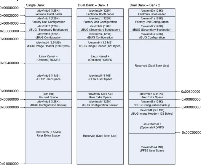
Default Flash Memory Map for XPort Pro
The following figure shows the flash layout as it is hard-coded in the Linux kernel.
Figure 5-2. Flash Layout – XPort Pro
/dev/mtd0 (128K) Lantronix BootLoader
/dev/mtd1 (128K) Factory Unit Configuration
/dev/mtd5 (4 MB) JFFS2 User Space /dev/mtd4 (3.5 MB) dBUG Image Header (128 Bytes)
Linux Kernel + (Optional) ROMFS
/dev/mtd8 (128K) dBUG Configuration Backup
/dev/mtd3 (128K) dBUG Configuration
/dev/mtd7 (384 KB) User Extra Space /dev/mtd2 (128K)
dBUG (Secondary Bootloader)
/dev/mtd5 (7.5 MB) User Extra Space
Flash Layout – XPort Pro
Single Bank Dual Bank – Bank 1 Dual Bank – Bank 2
/dev/mtd4 (3.5 MB) dBUG Image Header (128 Bytes)
Linux Kernel + (Optional) ROMFS 0x00000000 0x00080000 0x00060000 0x00040000 0x00020000 0x00400000 0x00800000 0x00880000
Reserved (Dual Bank Use)
0x01000000
/dev/mtd0 (128K) Lantronix BootLoader
/dev/mtd1 (128K) Factory Unit Configuration
/dev/mtd2 (128K dBUG (Secondary Bootloader)
/dev/mtd3 (128K) dBUG Configuration
/dev/mtd8 (128K) dBUG Configuration Backup
/dev/mtd7 (384 KB) User Extra Space /dev/mtd0 (128K) Lantronix BootLoader
/dev/mtd1 (128K) Factory Unit Configuration
/dev/mtd2 (128K) dBUG (Secondary Bootloader)
/dev/mtd3 (128K) dBUG Configuration
Reserved (Dual Bank Use)
0x00C00000 0x00860000 0x00800000
/dev/mtd4 (3.5 MB) dBUG Image Header (128 Bytes)
Linux Kernel + (Optional) ROMFS /dev/mtd5 (4 MB) JFFS2 User Space (384 KB) Unused Space 0x00860000 0x00880000 /dev/mtd5 (4 MB) JFFS2 User Space /dev/mtd8 (128K) dBUG Configuration Backup
You can easily make adjustments to better fit your needs. Partition sizes and locations that should not be altered are the first 4 flash areas. They are essential to be able to boot and configure the Linux kernel. Additional partitions can be added, and existing ones can be increased or shrunk (e.g. to adjust the space reserved for the kernel and ROMFS).
Please keep in mind, that some of the utilities like dbug-config and firmware update depend on the partition names and won’t work anymore if you rename the partitions without adjusting those utilities.
The partition definitions can be found in linux-2.6.x/drivers/mtd/maps/m520x.c:
static struct mtd_partition m520x_partitions_including_kernel[] = { {
.name = "LTRXbloader",
5 Flash Partitioning }, { .name = "LTRXconfig", .size = 0x10000, .offset = MTDPART_OFS_NXTBLK,
.mask_flags = MTD_WRITEABLE /* force read-only */
}, {
.name = "dBug",
.size = 0x10000,
.offset = MTDPART_OFS_NXTBLK,
.mask_flags = MTD_WRITEABLE /* force read-only */
}, { .name = "dBugConfig", .size = 0x10000, .offset = MTDPART_OFS_NXTBLK, }, { .name = "Kernel", .size = (DEFAULT_FLASH_SIZE / 2) - 0x40000, .offset = MTDPART_OFS_NXTBLK,
.mask_flags = MTD_WRITEABLE /* force read-only */
}, };
static struct mtd_partition m520x_romfs_in_flash_partition[] = { {
.name = "Romfs",
.size = 0, /* needs to be adjusted dynamically */
.offset = 0, /* needs to be adjusted dynamically */
.mask_flags = MTD_WRITEABLE /* force read-only */
}, };
static struct mtd_partition m520x_partitions_after_romfs[] = { {
.name = "UserSpace",
.size = MTDPART_SIZ_FULL, // gets overwritten below
.offset = MTDPART_OFS_NXTBLK }, { .name = "WritableFlash", .size = MTDPART_SIZ_FULL, .offset = 0x40000 } #ifdef CONFIG_MTD_RECOVER_PARAMS , { .name = "UserExtra", .size = 0x30000,
.offset = 0x400000 // gets overwritten below },
{
.name = "dBugConfBackup",
.size = 0x10000,
} #else /* CONFIG_MTD_RECOVER_PARAMS */ #ifdef CONFIG_MTD_BOOT_BANK , { .name = "UserExtra", .size = 0x40000,
.offset = 0x400000 // gets overwritten below }
#endif /* CONFIG_MTD_BOOT_BANK */ #endif /* CONFIG_MTD_RECOVER_PARAMS */ };
kernel + ROMFS root + blank JFFS2
This is the easiest deployable configuration available. The build process creates a ROMFS from the root file system and appends the Linux kernel to it. This layout is supported in two variations - both are created in the images/ directory per default:
Uncompressed: image.bin (dBUG copies the image (a concatenation of kernel and ROMFS) from flash to RAM)
Compressed: imagez.bin (dBUG uncompresses the compressed image (a concatenation of kernel and ROMFS) from flash to RAM)
Both files contain a small header for dBUG with a checksum and the destination address for the image in RAM.
The advantage of copying the ROMFS image into RAM is that the flash area where it resides on can be easily overwritten during a firmware update without interrupting normal operation of the device since the changes won't come into effect until after the next reboot.
The provided startup script (<install-dir>/linux/linux-2.6.x/drivers/mtd/maps/m520x.c) tries to mount the JFFS2 file system (/dev/mtd5) under /mnt/flash. Modify the script accordingly if you want to use this flash area for other purposes (e.g. splitting it up into multiple partitions). To convert a unit from any other flash layout to this layout:
1. Boot into dBUG and issue these commands (assuming that the network settings are properly configured, your TFTP server on your hosts is configured to serve files from /tftpboot and make copied the images in that location:
dBUG> dnfl /tftpboot/image.bin or
dBUG> dnfl /tftpboot/imagez.bin Address: 0x4001FF80
Downloading Image 'imagez.bin' from 172.19.239.1 TFTP transfer completed
Read 1255499 bytes (2453 blocks)
Must erase complete sectors (0x00080000 to 0x001BFFFF) Continue (yes | no)? yes
...
Flash Erase complete. 0x140000 bytes erased Program successfully flashed...
5 Flash Partitioning 2. Validate that the kernel command line is set to rootfstype=romfs:
dBUG> show watchdog: on silentboot: off romfs_flash: off bootbank: Single safebank: 0 netcon: on tftpsrv: on base: 16 baud: 115200
autoboot: Stop at prompt server: 172.19.239.1 client: 172.19.239.77 gateway: 172.19.0.1 netmask: 255.255.0.0 filename: /tftpboot/image.bin filetype: Image ethaddr: 00:20:4A:80:8C:7E dns: 172.19.1.1 bootfc: 0 maxbootfc: off kcl: rootfstype=romfs 3. Otherwise issue:
dBUG> set kcl rootfstype=romfs
4. Initialize/Erase the JFFS2 file system with: For all platforms (Single bank configuration)
dBUG> fl e 0x00400000 0x00400000
5. And run the freshly installed new kernel + ROMFS with:
dBUG> gfl
kernel + ROMFS root, preserving the JFFS2 partition
This configuration is almost identical to the previous one except that the JFFS2 area does not get touched. It is also the default configuration of the original µClinux distribution.
Follow the same steps as in the previous chapter but omit the flash erase command: For all platforms (Single bank configuration)
kernel + JFFS2 root
This configuration is intended to free up RAM for applications that require a considerable amount of memory (e.g. ssh, tcpdump). These applications cannot be run from a ROMFS configuration. One downside is that is very hard to implement a reliable firmware upgrade process for this flash layout. It is also more prone to file system corruption of important files then ROMFS, since everything is stored on a single write-enabled partition.
On a MatchPort AR it would look like this:
1. Download and flash the kernel image (you can use either linux.bin or the compressed version linuz.bin)
dBUG> dnfl linux.bin Address: 0x4001FF80
Downloading Image 'linux.bin' from 172.19.39.1 TFTP transfer completed
Read 1605760 bytes (3137 blocks)
Must erase complete sectors (0x00040000 to 0x001CFFFF) Continue (yes | no)? yes
...
Flash Erase complete. 0x190000 bytes erased Program successfully flashed...
2. Download and flash the jffs2 root image to its default location 0x400000. This has to be done in two steps. First download the JFFS2 partition image into RAM. dBUG always loads files to this address: 0x4001FF80. Then that RAM area can be flashed to the destination address in FLASH.
dBUG> dn rootfs.img Address: 0x4001FF80
Downloading Image 'rootfs.img' from 172.19.39.1 TFTP transfer completed
Read 4194304 bytes (8193 blocks) For all platform (Single bank)
dBUG> fl w 0x00400000 0x4001FF80 0x400000
... Flash Write complete. 0x400000 bytes written
3. Validate that the kernel command line is set to noinitrd rw rootfstype=jffs2 root=/dev/mtdblock5
dBUG> show
watchdog: on ...
5 Flash Partitioning
Otherwise issue:
dBUG> set kcl noinitrd rw rootfstype=jffs2 root=/dev/mtdblock5 And run the freshly installed new kernel + ROMFS with
dBUG> gfl
kernel + ROMFS root + JFFS2 + AUFS
This variation is created when you use the AUFS profile. The instruction to get the resulting files on the flash are identical to the ones described in the “kernel + ROMFS root + blank JFFS2” section.
One area where this feature might be very handy is configuration files. Just think of storing a static ip address for the device. Since the end user should be able to assign a static IP to the device, it needs to be stored on persistent storage. The problem is that /etc resides on a read-only file system. There are 3 possible solutions to this approach:
Put /etc on a writeable file system - this was the approach taken in the previous section.
Create a symbolic link for /etc/netcfg to a different file system that is write-enabled - that approach is used by the ROMFS + JFFS2 file system layouts.
Use a stackable file system like AUFS Let's look into the last solution.
Here we create /etc on our ROMFS partition. But we overlay /etc with a write-enabled JFFS2 partition. That means that Linux can use the files from ROMFS unless there is a version of the same file stored in the corresponding directory on the JFFS2 partition. For applications it looks like /etc is a regular write-enabled file system. But the big difference to the JFFS2 only solution we discussed in a previous section is that we always have a known good configuration in ROMFS to which can reverted to if something goes wrong with the JFFS2 partition. By omitting the overlay mount and since configuration and applications are cleanly separated, a firmware update is now possible.
Let's assume we have mounted our JFFS2 partition under /usr/local.
mkdir /etc.romfs
mount -o rebind /etc /etc.romfs
This allows access to the files that are really on the ROMFS partition in /etc via /etc.romfs.
[ -d /usr/local/etc ] || mkdir /usr/local/etc
mount -t aufs -o br:/usr/local/etc:/etc.romfs none /etc
From now on all changes made to files in /etc are actually written to /usr/local/etc.
This is exactly how the aufs profile is implemented. It can be found in <install-dir>/linux/linux-2.6.x/drivers/mtd/maps/m520x.c
This approach could be easily extended to overlap /bin for example. The ROMFS partition could include all absolutely essential software and additional applications could be stored in a separate partition. Even more layers are thinkable (JFFS2 on top of CRAMFS on top of ROMFS)
Custom Layout
It is possible to customize the flash layout by writing the image files to the desired addresses, and modifying the kernel command line options appropriately. But the recommended approach is to adjust <install-dir>/linux/linux-2.6.x/drivers/mtd/maps/m520x.c and recompile the kernel.
Let's assume you want an image consisting of the kernel followed by a JFFS2 root partition that uses all available flash space. Perform the following steps:
1. Download and flash the kernel image
dBUG> dnfl linux.bin Address: 0x4001FF80
Downloading Image 'linux.bin' from 172.19.39.1 TFTP transfer completed
Read 1396736 bytes (2729 blocks)
Must erase complete sectors (0x00040000 to 0x0019FFFF) Continue (yes | no)? yes
...
Flash Erase complete. 0x160000 bytes erased Program successfully flashed...
2. Determine the address where the jffs2 image will go to.
Since the dnfl command output from step 1 shows that the kernel was written to
0x001CFFFF, we will have to write the jffs2 image past this address. Note that the address must be at the start of a flash erase block. Flash erase blocks are 64KB (128KB on XPort Pro). In this example, the minimum address we can use would be 0x00200000, though in many cases it is a good idea to leave extra room for future upgrades of the kernel. For now we'll just use 0x00200000.
3. The default size for the JFFS2 file system is 4MB. It is hard-coded in
<install-dir>/linux/vendors/Lantronix/<platform>/config.arch. Since we have 6MB available, we want to make use of it. Look for the lines:
JFFS2_SIZE = 0x400000
in Config.arch and adjust the JFFS2_SIZE to 0x600000.
You need to rebuild rootfs.img to honor the last change. This can be achieved by just typing make under linux/
4. Download and flash the jffs2 root image. The starting address used here is 0x00200000, but it will vary depending on the feature set enabled in the kernel. The size of the jffs2 image used here is 6MB.
dBUG> dn rootfs.img Address: 0x4001FF80
Downloading Image 'rootfs.img' from 172.19.39.1 TFTP transfer completed
Read 6291456 bytes (12289 blocks) For all platforms
dBUG> fl w 0x00200000 0x4001FF80 0x600000
... Flash Write complete. 0x600000 bytes written
5 Flash Partitioning 5. Since you have decided not to change the partition layout in the kernel source (maybe
changing the kernel source would require intensive testing of the whole kernel again), the mptpart kernel command line option can be used to overwrite the partition scheme that is hard coded in the kernel.
To do this we will need to determine the sizes in KB of the kernel and jffs2 partitions. The size of the kernel partition here is 0x1C0000 bytes (0x180000 bytes on XPort Pro), which works out to be 1792KB (1536KB on XPort Pro). The size of the jffs2 partition is 0x600000 bytes (6144KB). Note that a flash partition may be larger than its corresponding image because they must begin and end on flash erase block boundaries.
For MatchPort AR or EDS1100 / 2100
dBUG> set kcl noinitrd rw rootfstype=jffs2 root=/dev/mtdblock5 mtdparts=mpt:64k(LTRXbloader),64k(LTRXconfig),64k(bootloader),64k(dB ugConfig),1792k(kernel),6144k(jffs2)
For XPort Pro
‘dBUG> set kcl noinitrd rw rootfstype=jffs2 root=/dev/mtdblock5 mtdparts=mpt:128k(LTRXbloader),128k(LTRXconfig),128k(bootloader),128 k(dBugConfig),1536k(kernel),6144k(jffs2)
6. And run the freshly installed new kernel + ROMFS with:
dBUG> gfl
Further details about the mtdparts kcl option can be found in (<install-dir>/linux/linux-2.6.x /drivers/mtd/cmdlinepart.c)
6
6
.
.
B
B
u
u
i
i
l
l
d
d
i
i
n
n
g
g
µ
µ
C
C
l
l
i
i
n
n
u
u
x
x
Configuration Profiles
Configuration profiles are used to configure the µClinux initial settings. The actual differences between the provided profiles are very subtle. They differ mostly in the number of applications that get activated and a few kernel settings. We highly encourage the user to compare them with each other and make necessary adjustments. A profile is selected during the initial make of µClinux but can be exchanged any time.
The profiles are located under
<install_directory>/linux/vendor/Lantronix/<platform>/profile/<profile-name>. A table describing these profiles is given below.
Table 6-1. Configuration Profiles
PROFILE ROMFS JFFS2 NFS IPv6 BUSYBOX
default yes yes no yes normal
compact yes yes no no compact
no_ipv6 yes yes no no normal
develop yes yes yes yes normal
aufs yes yes root only no normal
shared yes yes no yes normal
The configuration profiles are comprised of the following files:
config.linux-2.6.x configuration file for the Linux kernel config.uClibc configuration file for uClibc
config.vendor-2.6.x configuration file for user applications
The developer will be prompted to select a profile during the initial make. The profile can be changed later with the following commands:
$ cd <install-dir> $ make config
...
Configuration Profile
> 1. DEFAULT (LTRX_PROFILE_DEFAULT) (NEW) 2. DEVELOPMENT (LTRX_PROFILE_DEVELOP) (NEW) 3. NO_IPV6 (LTRX_PROFILE_NO_IPV6) (NEW) 4. COMPACT (LTRX_PROFILE_COMPACT) (NEW) 5. AUFS (LTRX_PROFILE_AUFS) (NEW)
6. SHARED (LTRX_PROFILE_SHARED) (NEW) choice[1-6?]:
6 Building µClinux
Kernel and Application Options
The simplest way to modify the kernel and/or application options or switch to a different profile is to run one of these commands from the installation directory.
Command Interface Type
make menuconfig ncurses/terminal window
make xconfig graphical GTK
make qconfig graphical QT3 (does not work to change kernel)
Although the look and feel for these options differ, they are identical in functionality. 1. Select Kernel/Library/Defaults Selection and press Enter.
Figure 6-1. uClinux Kernel/Library/Defaults Window
2. To modify the kernel settings, select Customize Kernel Settings, and press Y to include features.
Figure 6-2. uClinux Customize Application/Library Settings Window
4. At the bottom of the screen, select Exit and press Enter. Repeat this process for the parent window.
5. When prompted to save your new kernel configuration, select Yes and press Enter.
Figure 6-3. uClinux Save Configurations Window
6. To customize the kernel selected earlier, navigate to the kernel configuration and enable or disable the desired options. When finished, select and press .
6 Building µClinux
Figure 6-4. uClinux Save Configurations Window
7. To customize the application/library settings selected earlier, navigate through the
configuration the menu and enable or disable the desired options. When finished, select Exit and press Enter.
Figure 6-5. uClinux Distribution Configuration Window