629 |
P a g e
Implementation of Reed Solomon Encoder and Decoder
for Wireless Communications
L. Gnaneswari
1, Dr . V. Jagan Naveen
21
Electronics and Communication Engineering, GMRIT, Rajam (India)
2
Electronics and Communication Engineering, GMRIT, Rajam (India)
ABSTRACT
In Digital communication error correcting codes are used for detection and correction of errors. The most powerful and widely used is Reed Solomon error correcting codes and is part of channel coding in the family of linear block codes. It can correct both burst errors and erasures. Galois field arithmetic is used for encoding and decoding of Reed Solomon code. The process involves adding redundant data to the information message to withstand effect of noise, interference and fading and retrieving it at the receiver. The implementation of proposed work is done using the matlab.
Keywords – Reed Solomon codes, Generator polynomial, Encoder, Decoder, Parity bits
I.
INTRODUCTION
Error correcting codes are used for error correction and detection of errors. There are different types of error
correcting codes. Forward error correcting codes are mostly preferred in digital communication. In forward
error correction, reed Solomon codes are preferred due its burst error correction and detection and are part of
channel coding.
Reed Solomon codes are binary in nature and are a type of systematic linear block codes. These codes are
defined systematic because the original data contains the extra redundant data, block codes because the original
information is splitted into fixed block length and the size of block is „m‟ bit symbols and linear because each splitted block of „m‟ bitsymbol is valid. The process involves appending of redundant data at the end of the
message sothat when a number of errors are introduced eitherduring theprocess of transmission or on storage it
can be recovered at the receiver. This helps the signal bearing information to be protected from noise,
interference and fading when transmitted through channel.
In reed Solomon coding scheme, the symbols are elements of a finite field or galois field (GF). Galois field is
used because it contains a set of finite elements. Galoi field is represented as GF (zm) where „z‟ is prime
number and „m‟ can be any integer. Encoding and decoding of RS code uses galois field arithmetic. Galois
field arithmetic uses GF multipliers for encoding the message with parity symbols using a predefined algorithm
630 |
P a g e
Figure (1):
Block diagram of Communication channel
II. REED SOLOMON CODES
Rs codes are BCH codes and non-binary in nature. The RS codes are defined as RS (p, q) where p is
total number of words i.e. original data and parity and q is length of message. RS codes use Galois
field arithmetic because of finite fields [4]. Finite fields exist only when they are defined over GF
(Z
m), Z is a prime number and m can be any integer. There are two types of finite fields determined
by „m‟. When „m‟ is equal to 1 they are said to be prime fields and when „m‟ is greater than 1 they are
said to be extension fields. The elements of prime fields GF (p) are the integers in the following sets
{0, 1…p-1}. The elements of extension field GF (Z
m), usually the smallest possible prime number is
taken i.e. z=2.
The polynomial representation of elements over GF (2
m) as,
a
(m-1)X
(m-1)+a
(m-2)X
(m-2)
+……+a
1
x
1+a
0Where A(x)€ GF(2
m)
a
i€ GF (2) = {0,1}.
A primitive polynomial is predefined for every possible value of „m‟ and based on that a generator
polynomial is defined. Some of the primitive polynomials of predefined „m‟ are given in table below
m
Primitive polynomial
1
1+x
2
1+x+x
23
1+x+x
3, 1+x
2+x
34
1+x+x
4, 1+x
3+x
45
1+x
2+x
5, 1+x+x
2+x
3+x
56
1+x+x
67
1+x
3+x
7631 |
P a g e
9
1+x
4+x
910
1+x
3+x
10Codeword length N=2
m-1, Message length=k, Symbol length (m) =5
Error correcting capability (2t) =N-k
Figure (2): structure of code word
III CONSTRUCTION OF ENCODER
The construction of encoder is done using generator polynomial [3]. Encoding of RS (N, k) code is same as
BCH codes. The multiplication and addition must be performed over GF (2m) is the only difference between
them. In encoder, the message polynomial m(X) is divided with generator polynomial g(X) and the reminder
b(X) is added to the original message at the end of data. This forms an encoded data that can be retrieved at the
receiver and is shifted message polynomial.
Figure (3): RS encoder for GF (2
5)
For t-error correcting RS code of length p=2m-1, the input message to the encoder is of the form,
m(X)= a(m-1)X (m-1)
+a(m-2)X
(m-2)+……+a
1x 1
+a0, b(X) = X (N-k)
m(X) mod g(x), the resulting codeword ,
C(X) =b(X) +m(X).
632 |
P a g e
g(X) = (x-α)(x-α2)(x-α3)(x-α4)(x-α5).After multiplying all the terms in the equation we get, g(x) = x5-x4α16+x3α23-x2α26+xα25+α28.
IV.
RS DECODER
The decoder consists of four steps in error correction of received data. The decoder is designed in such a way
that it can detect and correct up to three errors. They computation involves:
1. Syndrome computation
2. Error position
3. Error evaluation
4.
Error correctionSyndrome computation:
In syndrome computation the received data is divided with generator polynomial and checked for reminder. If
there is no reminder then the data received contains no errors and if reminder exists then data is said to have
some errors. A polynomial is obtained that represents errors and it is represented in vector form. FFT is applied
to the vector to know the errors which gives DFT of the vector [5].
Si=
Ciα
(N-1-i)ERROR POSITION:
After syndrome calculation, the obtained polynomial is further processed for finding the position of errors. The
t- error positions are calculated using Berlekamp Massey algorithm. Here the roots are calculated by trial and
errormethod. The β (Z) is obtained will determine the error position [9].
ERROR MAGNITUDE:
The magnitude of error is calculated after error position. This helps to find the decoded data. This result gives by how much the original data is varied from received data. Error evaluation is done using gamma Ω (Z)
β΄ (Z) S (Z) = Ω (Z) mod Z
2tError correction:
The obtained magnitude is subtracted from received data to get the original data or the formula is used to get the
decoded output.
633 |
P a g e
Where is the error magnitude in the imth position in the codeword, „m‟ is a value less than the errorcorrecting capability of the code, Ω(Z) is the error magnitude polynomial β΄ is the formal derivative of the error locator polynomial β(Z), and α is the primitive element of the Galois field.
Fig (4): General architecture of Decoder
634 |
P a g e
VI SIMULATION RESULTS
The implementation of RS codes in MATLAB to understand the phenomenon as how the signal is being
encoded and, what would happen if the signal has some error and up to what extent, the decoder can detect and
correct errors. In first simulation MATLAB, a random symbol of integers was taken as input. These random
symbols were encoded using RS encoder. Following this the signal is passed through noisy channel, these
symbols were received at the decoder end. Now at the decoder end, the decoder can correct up to t symbols.
After correcting the error, however the decoder takes the redundant bits out which were generated while
encoding the symbols. To verify the capability of RS code in detecting and correcting the errors, it was
implemented as per the block diagram shown in figure (2). For this case one set of RS code is used for
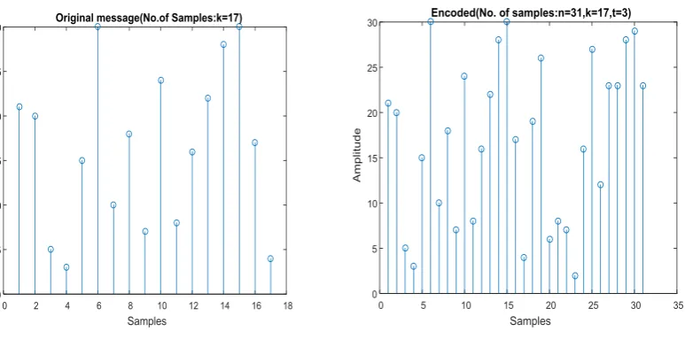
simulation, i.e. RS (31, 26). The figure (5) shows the result of randomly generated input data, where the
number of data points is equal to k i.e. k=17
Figure (5): Input samples Figure (6): Encoded data
This input data was encoded by RS encoder and the number of samples at the output of encoder is n (i.e. 31),
which is equal to message plus parity (in this case n=k+2t, where k=17 and t=3). This encoded data is adde with
some noise and the RS decoder detect the errors and correct„t‟ number of errors.
635 |
P a g e
VII CONCLUSION
Reed Solomon code process on block by block basis. The actual maximum code rate allowed depends on error
correcting code used. Reed Solomon code are systematic code for which the actual information appears
unaltered in the encoded data, redundant bits are added for detection and correction of error. Key idea behind
Reed Solomon code is data visualized as a polynomial.
In encoder redundant symbols are added using generator polynomial. In RS (31, 26) after encoding information
remaining same while extra 5 –bit parity symbol are added. Before data transmitted the encoder attached parity
symbol using a predefined algorithm. It was found that if the error is in parity symbols even then the decoder is
able to detect the output. The decoder first corrects the symbols and then removes the redundant parity symbols
from the code word and produces the original message. From the simulation result it has been shown that the
decoder can correct up to„t‟ number of errors.
FUTURE SCOPE: The proposed work is implemented in VHDL for FPGA implementation.
REFERENCES
[1]. Lee H., “A high speed Reed Solomon decoder for optical communication,” IEEE Transaction on circuits
and systems II, PP.461-465, 2005.
[2]. Yangquan wu, senior member, IEEE transactions on communication vol. 63, No.8, August 2015, “New
scalable decoder architectures for Reed Solomon codes” .
[3]. “Implementation of self-checking RS (n, k) encoder using VHDL”, IJRSI volume III, Issue II February
2016, ISSN 2321-2705, Sabita Mali department of electronics and instrumentation Engg, ITER,SOA
university, Bhubaneswar, Orissa.
[4]. IEEE Transactions on circuits and systems-I; regular papers, “Galois field arithmetic over GF (pm) for high
speed/low power error control applications, Thomas Conway, member, IEEE, VOL.51, NO.4, April 2004.
[5]. IEEE Transactions on communications, VOL.55, NO.12, Dec 2007, “A Fast Algorithm for the syndrome calculation in algebraic decoding of reed Solomon codes”, Tsung-Ching Lin, T.K.Troung and P.D. chen.
[6]. IEEE Transactions on information Theory, VOL.62, NO.10, October 2016, “ FFT Algorithm for binary
extension finite field and its applications to reed Solomon codes” Sian-Jheng rim, member IEEE,
Y.AL-Naffouri, Member IEEE, and Yung Hsiang S.Han,fellow,IEEE
[7]. Chu yu, Member, IEEE, and Yu-Shan Su, “ Two mode Reed Solomon decoder using simplified step by
step algorithm, IEEE Transactions on circuits and systems-II; Express Briefs, VOL.X,XXX,XXX.
[8]. “Implementation of Reed Solomon for CCSDS”, ICSP 2014 Proceedings, Ying Zhang, JuWang, Hungji
Zhao, School of information and electronics, Beijing institute of technology.
[9]. “Concurrent error detection in Reed Solomon encoders and decoders” G.C. Cardarilli, S. Pontarelli, M.Re,
and A.Salsano, IEEE Transactions on very large scale integration (VLSI) systems, VOL.15, NO.7, July