ANALYSIS OF DIFFERENT LENGTH OF SUB
CHANNELS AND DIFFERENT ORDER OF
MODULATION ON THE BASIS OF BIT ERROR RATE
IN OFDM SYSTEM
1
Anupam Dwivedi,
2Ajita Pathak
1, 2Department of Electronics and Communication Engineering, Amity University, U.P (India)
ABSTRACT
In order to accommodate a huge number of users under a single base station, their must be some flexibility
over the spectrum. Formerly we have a lot of multiplexing methods to accommodate large number of signals in
time and frequency domain. But at present we have to accommodate a large number of users in the fixed
bandwidth, without any degrade in quality of the received signal. So, orthogonality can be preserved over the
frequency response. This technology is now more common in the mobile communication domain, called
Orthogonal Frequency Division Multiplexing (OFDM). Initially user data is converted into the parallel form
and thenit is modulated using digital modulation techniques. Finally, they are followed by OFDM Modulator
and cyclic prefix can be inserted into the OFDM symbols. Here, I have worked on the measurement of BER for
different modulation techniques in OFDM technology. It has been considered that sub-channel size is not
constant. According to that I have concluded the overall idea regarding the performance under OFDM
technology.
Keywords: OFDM symbols, Cyclic Prefix, bit error rate, modulation order, sub-channel length.
I. INTRODUCTION
From past two decades communication domain has centred our attention on modulation and multiplexing
techniques to provide broadband transmission over wireless channels. OFDM is a multi-carrier transmission
technique [1] whichis used to provide high speed data rate over wireless noisy channels at little amount of
network complexity. Here the different subcarriers can be modulated separately [2]. It has the ability to reduce
the ISI and ICI, even it doesn’t require equalizer. ISI can be directly minimized using Cyclic Prefix (CP), which
is simply a guard time. This technology is most useful due to it’s better spectral efficiency and power efficiency.
But OFDM has some disadvantages - high peak to average power ratio (PAPR) [3] and bit error rate (BER). Bit
error rate is the important parameter to calculate the end to end performance measurement. There have so many
steps to generate this OFDM signal. The OFDM transceiver action can be made on a block by block basis. Here,
inverse Fast Fourier Transform (IFFT) and Fast Fourier Transform (FFT) operation can be performed at the
transmitter and receiver end, respectively. At the mapping area and serial to parallel converter before IFFT of
demodulation operation can be performed at the de-mapping area and parallel to serial converter after FFT of
receiving end. The type of modulation can be decided in accordance with the type of information. There have
present different order of modulations. In accordance to the modulation order the amount of error in the bit
information can be changed. So, I have worked on that issue to find the bit error rate for different modulation
orders and the different number of sub-channels. This research issue is based on the simulation work on the
basis of bit error rate of different modulation techniques. Before this work, there was little research on
performance evaluation of OFDM. Ref. [4] is performed on the basis of symbol error rate. In this research, new
technique was proposed tominimize SER of OFDM systems by adjusting the distribution of transmission power
among thesubcarriers. The performance analysis in Ref. [5] is performed on the basis of error correction coding
and interleaving. Here, the research result was capable to provide an average bit and frame error rates and
outage probabilities. The work under Ref. [6] was capable to provide the systembit-error rate on the basis of an
expression, which takes into an account of both AWGN and“nonlinear noise” effects. These works are not
sufficient for the analysis of system performanceon the issue of bit error rate for different modulation techniques
with different size of sub-channelsin OFDM system. To the best of my knowledge, this kind of work has not
been done for OFDMsystem. So, I have worked on this issue to execute a performance analysis on the basis of
acomparative graphical result. The remaining parts of this paper are organized as follows: In Sections II and III,
I give an overview of the basic principle of OFDM technology and Mathematical representation of OFDM
signal, respectively. Section IV presents an OFDM system with the proper mathematical view and the way of
insertion of cyclic prefix. The resource allocation method in OFDM technology can be described in Section V.
Section VI gives the idea about methods of modulation in OFDM technique. The performance evaluations of my
work are presented in Section VII. Finally, I conclude this paper in Section VIII.
II. BASIC PRINCIPLE OF OFDM TECHNOLOGY
In a traditional serial data transmission, the symbols can be transmitted sequentially, with the frequency
spectrum of each data symbol allowed to occupy the whole available bandwidth [7]. A parallel data transmission
system provides the possibilities to solve many of the problems encountered with serial data transmission
systems. In case of parallel system, the several sequential streams of data are transmitted simultaneously, so that
at any instant of time many data elements are being transmitted. In such kind of system, the available spectrum
of an individual data element normally occupies only a small part of the whole bandwidth as described in figure
1.
2.1 Mathematical Representation OF An of DM Signal
From the very beginning of a slot t = ts, the continuous time OFDM symbol can be described as:-
g(t)= Re{ rect(t-ts–Ts/2)exp[j2 (i/Ts)(t-Ts)} ……{1}
in the above equation t has required to meet ts≤t≤ ts+Ts
g(t)=0 for t<ts, or t>ts+Ts ……{1.a}
where, N denotes the number of sub-channels and TS denotes the time duration of an OFDM
symbols; bi (i = 0,1,2,.., N-1) is data symbol allocated to each sub-channel, f0 is the carrier
frequency of first subcarrier; and the function rect(t) =1, for |t|≤Ts/2.
The real part is called as in-phase component of the OFDM symbol; and the imaginary part is as called
quadrature component.
Now, the output of an OFDM signal using a complex description of equivalent baseband signal can be
expressed as:
g(t)= Re{ rect(t-ts–Ts/2)exp[j2 (i/Ts)(t-Ts)}
2.2 Ofdm System with the Insertion of Cyclic Prefix
Figure 3 depicts the overall modulation-demodulation techniques in OFDM system. One end of the transmitter,
blocks of information-carrying symbols are converted onto an N number of
Sub-streams using serial to parallel converter. Those streams can be modulated using an N number of
orthogonal waveforms with frequency fk, where, k= 0,…,N-1. This orthogonal waveform modulation is
performed using an IFFT and a parallel to serial converter. The OFDM modulatedsignal can be computed as the
IFFT of the basic smallest elementary unit associated with differentsubcarriers. The output of the IFFT is
considered as the sum of complex exponential functionsknown as basis functions, complex sinusoids,
harmonics, or the tones of a multi-tone signal [8].Now, let us consider one of these tones or harmonics, which is
the complex exponential functionassociated with a particular subcarrier. That can be described through the
discrete representation:
=
…… (
2)
where, fk = k/Ts = k f [ f is amount of subcarrier spacing and Tsis symbol duration]; here is equivalent with
fk.
If the channel response is Hi (there are total L+1 number of channels) can be operated on the inputtransmitted
signal then final output can be defined as –
i i
……..(3)
where, di is the amount of multipath delay for the particular assigned channel.
Now, due to linearity issue is concerned, when the OFDM signal is considered for a multipath fading channel
then each of its complex exponential components is also subjected to the identical channel model. Therefore, it
can be computed that the received version of each subcarrier component of the OFDM signal as
=
i………(4)
After the converter, last L number of points can be appended to the beginning of the sequence as the CP. This
CP is a special kind of spectral time guard in the symbol transitions. Finally the resulting samples are then
shaped and transmitted. These transmitted blocks are then referred to as a processed OFDM symbol.
After the addition of CP we can substitute the expression of x(n) | _=k_f = akej2_kn/N, if and only if the
multipath propagation delay is less than or equal to the length of CP. Otherwise, with even asingle delay value
outside the range of the length of CP, we cross the OFDM symbol boundaryand the orthogonality between the
subcarrier components can be lost. Now, it can be assumed thatthe delay spread is lying within the range of the
length of CP. So, received subcarrier componentcan be defined as a function of transmitted subcarrier.
=
i k... (5)
Cyclic prefix insertion is an essential function during the generation of OFDM signal. A cyclic prefix is
necessary to avoid the interference from previously transmitted OFDM symbols. Cyclic prefix insertion may be
observed as a useless operation since it is simply repeats a copy of the existing data in the OFDM symbol and
does not add any new information. But it is necessary for multiple reasons. It helps to maintain orthogonality
between the subcarriers in the receiver, which is one of the bases of an orthogonal frequency division
transmission. This CP is used to provide a periodic extension to the OFDM signal through which a “linear
convolution” operation can be performed on the transmitted signal by the channel, can be approximated by a “circular convolution” operation [9].
Figure 2 depicts the OFDM symbol with the CP. There are two kinds of applicable CP in thepresent day
scenario – normal and extended. Tsym is the symbol duration. The mathematicaldefinition of this symbol
duration is –Tsym = M/W + Tg, where, M is the number of samples can be chosen to be the power of 2 and W is
the total bandwidth, and Tg is the duration of cyclic prefix. Now, the receiver can be able to do the reverse
point of a block and the proper demodulation window. In the next step, it has required to remove the CP (which
contains the ISI) and an N’ (N’ = N) point sequence is to be converted from serial to parallel form and fed it to
the FFT. The outputs of the FFT are symbols modulated on N subcarriers, each multiplied by a complex channel
gain. Depending upon the availability of the channel information, different types of demodulation or decoding
can be used to recover the information bits. The output of the multipliers are then integrated over the period of 0
to T
to get back the estimated signals A’k,0 … A’k,N’-1, which are then converted from parallel to serial data; after
the decoding, binary form of transmitted signal is obtained.
III. RESOURCE ALLOCATION
The traditional fixed resource allocation is not optimal, since the scheme is predetermined regardless of current
channel conditions. On the other hand, dynamic resource allocation assigns a dimension adaptively to the users
based on their channel gains. Due to the cause of time-varying nature of the wireless channel, dynamic resource
allocation makes full utilization of multiuser diversity to achieve higher performance [10]. So, multicarrier
application OFDM is most useful to achieve good performance over the other tradition fixed channel
application. In case of OFDM access mechanism, a subset of subcarriers is assigned to each user and thus, the
number of subcarriers to be assigned to each user must be pre-scheduled by the system. A basic unit of this
resource allocation in OFDM access mechanism is sub-channel. This sub-channel is a group of subcarriers. On
the basis of the allocation of sub-channel, resource allocation mechanism of OFDM can be categorized in three
different classes – Block, Comb and Random type allocation method. Block type is used under the assumption
of slow fading channel. Comb Type is used to satisfy the need for equalization, when the channel is varying too
fast. Random is used under the consideration of fast fading channel. Block type configuration is used to map the
pilot subcarriers on all the subcarriers. Comb type is used to map on the certain number of subcarriers. In case of
Random type, pilot subcarrier indexes can be changed periodically [11-12]. There is different length of these
IV. MODULATION TECHNIQUES
In figure 3 the input data stream can be modulated by a QAM modulator and the complex symbol stream can be
produced as S0, S1, …, SN-1. This symbol stream is passed through a serial-to parallel converter. The output of
this converter is a set of N parallel QAM symbols like S0, S1, …,SN-1 corresponding to the transmitted symbol
over each subcarriers [13-14]. At the receiver end the output of the FFT can be passed through the parallel to
serial converter and ultimately the output of this converter can be demodulated by the QAM demodulator to
recover the original data. Here, I have used different order of modulation with differentnumber of sub-channels
to observe the bit error rate for OFDM signal. Modulation order has been taken as 4 (QPSK), 8 (8-QAM) and 16
(16-QAM).
V. SIMULATION AND EXPERIMENTAL RESULTS
In this research work, 3 different sub-channels can be taken to perform a comparative analysis. Here I have done
my experimental work through MATLAB simulation software. 100 number of iterations is taken for each of the
experimental results. I have taken the following parameters and set their value as given in Table I.
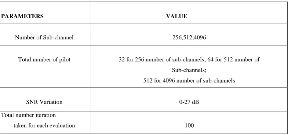
Table I. Set up Values of Experimental parameters
PARAMETERS VALUE
Number of Sub-channel 256,512,4096
Total number of pilot 32 for 256 number of sub-channels; 64 for 512 number of
Sub-channels;
512 for 4096 number of sub-channels
SNR Variation 0-27 dB
Total number iteration
taken for each evaluation 100
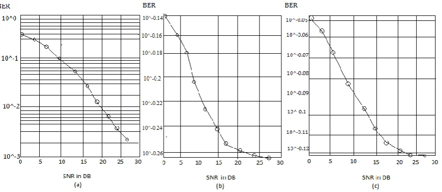
Case study :1
Fig 4: Bit error rate for different level of SNR (in dB) for –(a) modulation order 4,
(b) modulation order 8 and (c) modulation order 16 with256 number of sub-channels.
If we observe the above figure then we will get an idea about the amount of bit error rate and best performer
(modulation order of 4) within the different order of modulations at 0dB level of SNR, whereas the same kind of
result also can be observed at higher level of SNR. the other 2 different order of modulations). Finally, I got
right option for the higher level of SNRand that is 4th order modulation means QPSK.
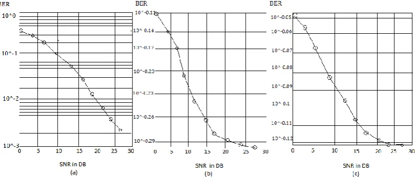
Case study :2
Number of sub-channel taken –512
Fig 5 : Bit error rate for different level of SNR (in dB) for – (a) modulation order 4,
(b) modulation order 8, and (c) modulation order 16 with 512 number of sub-channels.
If we compare above two figures (figure 4 and 5), it can be observed that the amount of bit error can be
minimized for the two higher order modulation (modulation order 8 and 16) in figure 5 with respect to figure 4,
whereas the bit error rate is almost same for lower order modulation (modulation order 4). So, it can be said as,
Case study :3
Number of sub-channel taken –4096
Fig 6 :Bit error rate for different level of SNR (in dB) for – (a) modulation order 4,
(b) modulation order 8 (c) modulation order 16 with 4096 number of sub-channels.
In this case, I have taken an extra large number of sub-channels to observe the continuation of the above result
under the case study 2.
Discussion of the above results
Finally, I got the expected result, which is similar with the analytical work. If we increase thelevel of SNR, then
the amount of bit error rate for modulation order 16 can be saturated after a certain level of the threshold value.
VI. CONCLUSION
In this paper, I explore an idea about the comparative performance evaluation on the basis of bit error rate of a
different order of modulation with respect to different size of sub-channels. I studiedthat bit error rate can be
increased with the increasing size of channel length and bit error rate canbe decreased with the increasing size of
sub-channels. We know that the higher amount of dataaccommodation can be possible through the higher order
modulation. So, it can be concluded thatthe better performance with higher data accommodation capacity in
OFDM system can beavailable through the large length of sub-channel with higher order of modulation.
REFERENCES
[1] Wong, C. Y., Cheng, R. S., Lataief, K. B., and Murch, R. D., “Multiuser OFDM with adaptive subcarrier,
bit, and power allocation”, IEEE Journal on Selected Areas in Communications, vol. 17, no. 10, pp.
1747-1758, Oct. 1999.
[2] Wang, F., and He, X., “The Performance Analysis of AFH_OFDM System Based on Simulink”, IEEE
7th International Conference on Wireless Communications, Networking and Mobile Computing
[3] Lafta, Y. A., and Johnson, P., “High performance OFDM systems for digital video broadcasting
terrestrial (DVB-T)”, International Journal of Digital Information and Wireless Communications
(IJDIWC), vol. 2, no. 1, pp. 66-74, 2012.
[4] Wang, X., Tjhung, T. T., Wu, Y., and Caron, B., “SER performance evaluation and optimization of
OFDM system with residual frequency and timing offsets from imperfect synchronization”, IEEE
Transactions on Broadcasting, vol. 49 no. 2, pp. 170-177, Jun. 2003.
[5] Witrisal, K., Kim, Y. H., and Prasad, R., “A novel approach for performance evaluation of OFDM with
error correction coding and interleaving”, IEEE Vehicular Technology Conference, Vol. 1, pp. 294-299,
Amsterdam, DOI : 10.1109/VETECF.1999.797143, Sep. 1999.
[6] Santella, G., and Mazzenga, F., “A hybrid analytical-simulation procedure for performance evaluation in
M-QAM-OFDM schemes in presence of nonlinear distortions”, IEEE Transactions on Vehicular
Technology, vol. 47 no. 1, pp. 142-151, Feb. 1998.
[7] Zou, W. Y., and Wu, Y., “COFDM: An overview”, IEEE Transactions on Broadcasting, vol. 41, no. 1,
pp. 1-8, Mar. 1995.
[8] Zarrinkoub, H., “Understanding LTE with MATLAB: From Mathematical Modeling to Simulation and
Prototyping”, John Wiley & Sons Pub., 2014.
[9] Dahlman, E., Parkvall, S. and Sköld, J., “4G LTE/LTE-Advanced for Mobile Broadband”, Elsevier,
2011.
[10] Shen, Z., Andrews, J. G., and Evans, B. L., “Adaptive resource allocation in multiuser OFDM systems
with proportional rate constraints”, IEEE Transactions on Wireless Communications, vol. 4, no. 6, pp.
2726-2737, Nov. 2005.
[11] Socheleau, F. X., Ciblat, P., and Houcke, S., “OFDM system identification for cognitive radio based on
pilot-induced cyclostationarity”, IEEE Wireless Communications and Networking Conference, WCNC
2009, pp. 1-6, Budapest, DOI: 10.1109/WCNC.2009.4917840, Apr. 2009.
[12] Asadi, A., and Tazehkand, B. M., “A New Method to Channel Estimation in OFDM Systems Based on
Wavelet Transform”, International Journal of Digital Information and Wireless Communications
(IJDIWC), vol. 3, no. 1, pp. 1-9, 2013.
[13] Goldsmith, A., “Wireless communications”, Cambridge university press, 2005.
[14] Armstrong, J., “Analysis of new and existing methods of reducing inter carrier interference due to carrier
frequency offset in OFDM”, IEEE Transactions on Communications, vol. 47 no. 3, pp. 365- 369, Mar.