A Comparative Study of Flux Cancelation among Multiple
Interconnected Modular Pads in Lumped IPT System
Chun Qiu1, *, Kwok-Tong Chau1, Zhen Zhang1, and Tze Wood Ching2
Abstract—A lumped inductive power transfer system (IPT) with multiple modular pads differs from a stand-alone system. The magnetic coupling between adjacent modules is affected by the flux cancelation which further affects the power transmission. Thus, it is important to investigate the relationship between flux cancelation and system configuration. In this paper, the basic connection and operating mechanism for a modular IPT system are first discussed. Six cases are designed for two scenarios, including single and multiple secondary modules. Performances are compared in various primary excitation modes and secondary connection modes. Results show that the direction of canceled flux is determined by these modes. Matched modes will bring either a higher or a more stable coupling. And unmatched modes between primary and secondary sides tend to have the lowest coupling performance due to severe flux cancelation. Results provide a guidance for system design aiming at different power transfer characteristics.
1. INTRODUCTION
Inductive power transfer (IPT) delivers energy wirelessly via magnetic coupling [1–3]. A lumped IPT system comprises multiple transmitting pads. Compared to a single elongated conductor (or track), only the pads with considerable coupling to the secondary side are energized, bringing high efficiency and low electromagnetic interference (EMI) [4]. The flexible structure also simplifies system expansion and maintenance [2]. For current system, the distance between nearby pads is far enough to ignore magnetic interaction [5]. However, the effective time for power transmission is very short when the secondary pad (e.g., inside an electric vehicle (EV)) is moving at a high speed. This causes unnecessary high volt-ampere (VA) rating of the power source. Therefore, a better choice is a continuous layout. Consequently, the interaction among adjacent pads should be considered.
Alternating current in the primary pads produces a time-varying magnetic field. When multiple pads are closely placed, the magnetic flux with opposite polarities will cause an absence of electromotive force (EMF) in the secondary coil at specific positions. This phenomenon is called flux cancellation. Similarly, the cancellation also occurs at the secondary side when the total flux threading the coil add to zero. Factors that influence the cancellation could be phase difference between driving currents and connection of the secondary modules. Inappropriate configuration will cause serious cancellation that impedes power transmission. For this reason, a comparative study on this issue is important for a multiple modular system with a tight layout.
Due to the complexity of this study, which includes electromagnetic analysis under various configurations, the experimental validations are less feasible than finite element analysis (FEA) tools such as the software named JMAG. The accuracy of this magnetic analysis tool has been validated in previous research with experimental results [6]. The aim of this study is to provide a guidance for
Received 7 June 2016, Accepted 4 August 2016, Scheduled 12 August 2016
* Corresponding author: Chun Qiu ([email protected]).
1 Department of Electrical and Electronic Engineering, University of Hong Kong, Hong Kong, China. 2 Department of
modular IPT system design. The paper begins with an introduction of fundamentals of the IPT system and operating mechanism of the proposed modular topology. It then discusses three issues related to the flux cancellation, including connection method of the modular pads, excitation mode and configuration of the unpowered pads. For different configurations, flux cancellation is studied with a further inquiry on magnetic coupling and power transfer performance. The advantages and disadvantages are compared followed by a suggestion on system design.
2. IPT SYSTEM WITH MODULAR PADS DESIGN
2.1. Fundamentals of IPT system
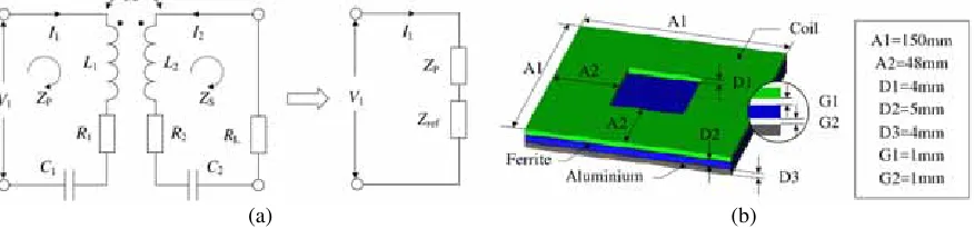
A typical IPT system (see Fig. 1(a)) consists of a pair of magnetically coupled coils (L1 and L2) with a
mutual inductance ofM. The primary coil is driven by a high-frequency power supply unit with either a current source (I1) or a voltage source (V1). There are often capacitive compensations (C1 and C2)
on both primary and secondary sides to minimize the VA rating of the power supply and maximize the power transferred to load. The series-series (SS) compensation topology is adopted, which means that C1 and C2 are both connected in series with L1 and L2. A basic SS topology IPT system with ideal
source is shown in Fig. 1(a). ZP andZS are the total impedances in the primary and secondary circuits, respectively, where R1 and R2 stand for the parasitic resistance.
When the operating frequency remains constant to the nominal frequency (ω0), the power
transferred to load is preliminarily dependent on the reflected impedance Zref, as given by Eq. (1).
Therefore, a relatively consistent mutual inductance M is desirable, as it simplifies the design and control of the power supply converters. Additionally, for a specific magnetic structure, the output VA rating is determined by the uncompensated power (Pun) and loaded quality factor of the secondary circuit (Q2) (see Eq. (2)). For an LC resonator, the native quality factor is defined by the inductive
reactance divided by the internal resistance. When the LC resonator is connected to the load, the total loss is governed by the internal resistance and the equivalent load resistance RL. Thus Q2 is
introduced. The value of RL, which is defined by the voltage-to-current ratio, is controlled by an electronic converter. A lowerRL will result in a higherQ2but lead to higher current losses and stresses
in components. Therefore,Q2 is typically constrained to 4–6, andPun becomes the most direct and fair
index to assess the power transfer capability [6].
(a) (b)
Figure 1. Basic IPT system. (a) Circuit model for series-series (SS) topology. (b) Proposed modular pad design.
PL = (ReZref)I12, Zref = ω
2 0M2
ZS (1)
PL = PunQ2, Pun=VOCISC=ω0M 2
L2 I 2
1 (2)
2.2. Design of Modular Power Pad
saturation [2, 3, 7]. There are two most noteworthy indicators, the mutual coupling and the native quality factor, which determine the power transfer ability and power transfer efficiency. First of all, a square pad is favourable due to its capability of covering a larger area in a single layer and better misalignment tolerance than a round pad [8]. A larger coil with larger number of turns will enhance coupling. However, a much longer side length than the transmission distance is proved unnecessary [3]. Second, there is often a compromise between the mutual coupling and quality factor in the pad design. For example, higher operating frequency will increase transmission ability but sacrifice the transmission efficiency at a certain quality factor [2, 3]. Using ferrite material will enhance coupling but lead to additional iron loss. Applying aluminium shielding will help control the unwanted leakage flux but increase the eddy current loss.
To simplify the design, a 3.3 kW power pad for electric vehicle charging is scaled down, as shown in Fig. 1(b) [9]. The single-sided flux characteristic helps to reduce unwanted leakage flux on the back of the pad by using a ferrite layer followed by aluminium shielding plate. The pad consists of a 12-turn coil wound with litz wire with a square slot in the centre of the pad. The coil is driven by a 23 A/85 kHz constant current source. Thus the gauge of the litz wire strand is selected as AWG38 (American wire gauge) according to the operating frequency. The number of strands is selected as 162 to achieve an equivalent current density around 2 A/mm2. The flux path height is 75 mm for the proposed primary
pad array, which is enough for most electronic devices and also satisfies the smallest air-gap for EV charging.
2.3. Operation for Modular Pad IPT System
(a) (b)
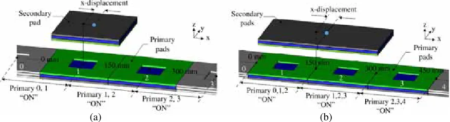
Figure 2. Structure of modular lumped pads system. (a) Single secondary pad. (b) Multiple secondary pads.
An IPT system with modular pads for dynamic charging is designed (see Fig. 2). In this design, the secondary pad is allowed to move along the primary pads array, which is suitable for the applications such as wireless powered city tram or mobile transfer robot in the warehouse. The primary array can also be further expanded iny-axis, enabling two-dimensional movement of the secondary pads. However, the study in this paper will be mainly focused on a one-dimensional layout. But the analysing method and corresponding results can be adapted to a two-dimensional system without too much effort.
3. FLUX CANCELATION BETWEEN ADJACENT PADS
3.1. Interconnection of Primary Pads
(a) (b)
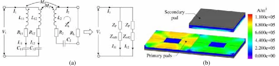
Figure 3. System with paralleled primary pads. (a) Circuit model. (b) Current density in primary coils.
The coils of modular primary pads can be interconnected in series or parallel. For the series connection, the current through each coil has the same current density. The superimposed magnetic field will be reinforced or canceled depending on the phase difference, which is elaborated in Section 3.2. As for the parallel connection, the current is not equally allocated. Fig. 3(a) shows a series compensated IPT system with two paralleled primary coils. The reflected impedance in each branch is given by Eq. (3). In the worst case, the secondary pad is aligned with one of the primary pads (e.g., the one on the right), leaving the other pad nearly uncoupled. Consequently, the uncoupled pad has a much higher current because of a zero reflected impedance (Zref1) in the primary circuit branch. Simulation
based on FEA using JMAG proves this inference, as shown in Fig. 3(b). Conclusively, the parallel interconnection is unacceptable because it not only reduces the transferred power, but also increases the loss and leakage flux.
Zref1 = ω 2M
1(M1+M2))
ZS+ω2M2(M2−M1)/ZP
Zref2 = ω 2M
2(M1+M2))
ZS+ω2M1(M1−M2)/ZP
(3)
3.2. Excitation Modes for Primary Pads
The magnetic performance of the modular system is not a simple superposition of the root mean square (RMS) value of the flux produced by each module. Actually, the fluxes generated by adjacent modules cancel with each other, and this characteristic is phase-angle related. Any arbitrary phase difference may exist when independent power supplies are used without synchronization. However, when single power source is employed, two modes are the most dominant. The first one is the in-phase mode. In this mode, currents in pad 1 and pad 2 have zero phase difference. In contrast, the out-of-phase mode has a phase difference of 180 degrees, as shown in Fig. 4(a) and Fig. 4(b).
(d)
(a) (b)
(c)
Figure 4. Flux pattern for primary pads in different excitation modes. (a) In-phase mode. (b) Out-of-phase mode. (c) Simulated flux pattern and density in in-phase mode. (d) Simulated flux pattern and density in out-of-phase mode.
(d)
(a) (b)
(c)
Figure 5. Simulated directional flux pattern and density. (a) Horizontal flux with in-phase mode. (b) Vertical flux with in-phase mode. (c) Horizontal flux with out-of-phase mode. (d) Vertical flux with out-of-phase mode.
3.3. Total Coupled Flux by Secondary Pads
The coupling between the primary and secondary pads is determined by a variety of factors including the primary excitation modes, number of the secondary pads and secondary connection. In this section, three cases are designed to explore this relationship. The first case includes a single secondary pad, and the last two cases include double secondary pads with in-phase and out-of-phase connections. All three cases are evaluated under two excitation modes, as introduced in Section 3.2. The flux density at the designated 75 mm clearance is measured and decomposed into horizontal and vertical components. The enclosed flux by the secondary pad is evaluated to finding a general performance as well as the worst coupling positions.
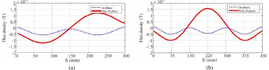
For the single secondary pad scenario, the flux in the vertical direction is supposed to dominate the coupling. As seen in Fig. 6(a), the vertical component of out-of-phase excitation has a symmetrical distribution along thex-axis, while the in-phase excitation produces a vertical flux on only one side of thex-axial. As a result, for the out-of-phase mode the total coupled flux by the secondary pad will show two peaks when it is aligned to the centre of the primary pads. It will also encounter a zero coupling zone at the common boundary. As for the in-phase mode, the coupling will be relatively stable which is favourable for IPT system.
(a) (b)
Figure 6. Simulated flux density at the designated 75 mm height. (a) Vertical flux with single secondary pad. (b) Vertical flux with multiple secondary pads.
For the cases of double secondary pads, three primary pads are simultaneously turned on, as illustrated in Fig. 2. The total coupled flux density in the vertical direction is studied with respect to the relative position of the secondary coils. Although the horizontal flux will enhance magnetic coupling by improving the coil structure, the major contribution to the induced voltage comes from the vertical flux component in this system. Under the out-of-phase excitation mode, flux cancelation will occur at three possible positions (i.e., 150 mm, 225 mm and 300 mm) depending on the secondary connection mode. As for the in-phase excitation mode, the flux density has a large bias with a periodical variation of one pad length. This may cause a severe flux cancelation when the two secondary pads are connected in the out-of-phase mode, because the coupled fluxes for the coils are always equal in amount but opposite in direction, as shown in Fig. 6(b).
3.4. Unpowered Adjacent Pad
(a) (b)
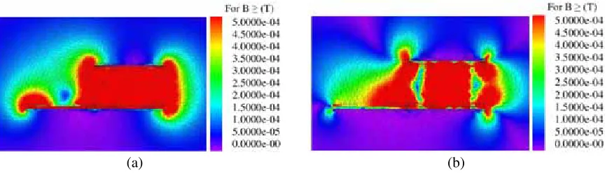
Figure 7. Flux cancelation with adjacent pad unpowered. (a) The left pad short-circuited. (b) The left pad open-circuited.
As shown in Fig. 7(a), the flux has an obvious cancelation above the unpowered pad in the short-circuit connection, and the flux above the activated pad is unaffected. However, in the open-short-circuit mode, the flux cancelation undesirably occurs inside the main transmission path, and the leakage flux above the unpowered pad is much higher than that in the short-circuit connection (see Fig. 7(b)). As for the impact on source power, both connection modes cause additional reactive power, and it is even higher in the open-circuit connection (see Table 1). The existence of a nearby pad will change the self-inductance of the pad in action. This change will cause the detuning of the LC resonant circuit and eventually lead to additional reactive power. Additionally, a less than 2% increase of active power is seen for the short-circuit mode, which is caused by the resistive loss of the short-circuit coil. In conclusion, the short-circuit mode is favoured for the unpowered pad for its better performance.
Table 1. Impact of unpowered pad on source power.
Connection Pin (W) Sin (VA) PL (W)
Open-circuit 548.39 653.10 500
Short-circuit 555.80 596.52 500
4. SIMULATION RESULTS AND DISCUSSION
3D FEA has been applied by JMAG to verify the previous analysis. The equivalent mutual inductance (Meq) and the secondary uncompensated power (Pun) are chosen as the performance indicators for magnetic coupling and power transfer capability. Two scenarios are set up for both single and multiple secondary pads, as illustrated in Fig. 2. Multiple points are simulated under different displacements to show a dynamic characteristic when the secondary pads move along the primary array. A constant 23 A/85 kHz current source is employed for all scenarios and cases. The litz wire used for the coil windings is simulated as a perfect copper block with uniform current distribution. This is similar to how stranded litz wire operates in actual situation. The eddy current in the aluminium shielding is considered and simulated by using JMAG with a finite conductivity of 2.4×10⁷S/m. Meanwhile, for the simulation, the N87 ferrite is adopted with an initial relative permeability μir of 2200.
4.1. Cumulative Coupling Performance
to the out-of-phase excitation. The latter has a drastic fluctuation with much higher peaks and zero valleys at the boundary of adjacent pads. Double secondary pads system has a similar performance when the primary and secondary pads are connected in the same mode (e.g., both in-phase). The all out-of-phase mode (OO) has a stronger coupling with fluctuation whereas the all in-phase mode (II) has a smaller but more stable coupling. It is worth noting that the worst combination occurs with in-phase primary and out-of-phase secondary, which results in a whole range zero magnetic coupling, as shown in Fig. 8(b).
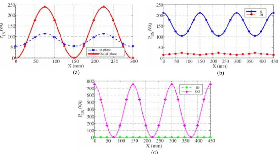
4.2. Power Transfer Capability
Pun is obtained using two separate simulations for the open-circuit voltage (VOC) and short-circuit current (ISC), respectively. In general, the out-of-phase connection for both primary and secondary (the OO mode) shows the highest power transfer capability. The both in-phase connection (the II mode) has a merit of showing no null of power points in the whole range, as shown in Fig. 9(b). The interoperability is poor for the IO or OI modes.
(a) (b)
Figure 8. Simulated equivalent mutual inductance related tox-axis displacement. (a) Single secondary pad setup. (b) Multiple secondary pad setup.
(c)
(a) (b)
4.3. Suggested Design Rules
Ideally, Meq and Pun are preferred to be constant in magnitude at different x-axis displacements. However, it is not achievable with this system architecture. Thus, the choice of the most suitable configuration of the modular pad system depends on the type or nature of application. For the low power charging platform for electronic devices, the demand on free-positioning is most critical. To avoid occasionally putting the secondary pads on the null of power position, the in-phase mode should be applied on both sides. And the coil pattern could be further optimized to smooth out the fluctuation on coupling effect [10]. As for the high power dynamic charging such as on-road EV, the secondary pads are continuously in motion. As a result, the large fluctuation on coupling is averaged, and high power transfer capability becomes the first consideration. Therefore, the out-of-phase mode should be used on both sides.
5. CONCLUSION
In this paper, a lump pad IPT system constructed by modular pads on both primary and secondary sides is introduced. The interconnection methods and excitation modes for the modular pads are investigated using the FEA method by JMAG. For the connection of primary modules, the parallel method is proved to be inappropriate because the weakly coupled pads share a larger driving current and produce additional losses and unwanted leakage flux. For the unpowered pads, the short-circuit connection shows better performance than the open-circuit connection. The flux above the unpowered pad is canceled out by the induced current without increasing too much demand on the power source.
The work presented in this paper shows that the phase difference between the primary and the secondary currents has an impact on the magnetic coupling. Generally, the in-phase mode causes a flux cancelation in the horizontal direction, whereas the out-of-phase causes a flux cancelation in the vertical direction. Among all excitation and connection modes, the out-of-phase on both sides has the most prominent magnetic coupling and therefore the highest power transfer capability. And the in-phase mode on both sides has the most stable coupling, making the power transfer less sensitive to positions. The system design should be selected based on specific applications. However, the opposite modes between primary and secondary pads are proved to have a poor cooperation. The captured flux by the secondary coil is either fully canceled or orthogonal to the secondary flux path, which impedes the power transfer.
ACKNOWLEDGMENT
This work is supported and funded by a grant (Project No.: HKU SPF 201309176048) from The University of Hong Kong, Hong Kong, China.
REFERENCES
1. Li, C. J. and H. Lin, “Investigation of wireless power transfer using planarized, capacitor-loaded coupled loops,”Progress In Electromagnetics Research, Vol. 148, 223–231, 2014.
2. Poon, A., “A general solution to wireless power transfer between two circular loops,” Progress In Electromagnetics Research, Vol. 148, 171–182, 2014.
3. Robichaud, A., M. Boudreault, and D. Deslandes, “Theoretical analysis of resonant wireless power transmission links composed of electrically small loops,” Progress In Electromagnetics Research, Vol. 143, 485–501, 2013.
4. Park, C., S. Lee, S. Y. Jeong, G. H. Cho, and C. T. Rim, “Uniform power I-type inductive power transfer system with DQ-power supply rails for on-line electric vehicles,” IEEE Trans. Power Electron., Vol. 30, No. 11, 6446–6455, 2015.
6. Budhia, M., J. T. Boys, G. A. Covic, and C. Y. Huang, “Development of a single-sided flux magnetic coupler for electric vehicle IPT charging systems,”IEEE Trans. Ind. Electron., Vol. 60, No. 1, 261–270, 2013.
7. Nagendra, G., G. A. Covic, and J. T. Boys, “Determining the physical size of inductive couplers for IPT EV systems,” IEEE J. Emerg. Sel. Topics Power Electron., Vol. 2, No. 3, 571–583, 2014. 8. Qiu, C., K. T. Chau, C. Liu, W. Li, and F. Lin, “Quantitative comparison of dynamic flux
distribution of magnetic couplers for roadway electric vehicle wireless charging system,” J. Appl. Phys., Vol. 115, No. 17, 17A334, 2014.
9. Lin, F., G. A. Covic, and J. T. Boys, “Evaluation of magnetic pad sizes and topologies for electric vehicle charging,”IEEE Trans. Power Electron., Vol. 30, No. 11, 6391–6407, 2015.