Three phase Shunt Active power filter for harmonic reduction in
non linear loads
M.Rajendra Prasad & A Krishna Nag
Asst Professor,
Department of EEE, Dadi Institute of engineering and Technology,Anakapalli
[email protected]
,[email protected]
Abstract—Harmonics contamination is a serious and a harmful problem in electrical systems. Active power filtering constitutes one of the most effective proposed solutions. A shunt active power filter that achieves low current total harmonic distortion, reactive power compensation, is presented. The topology is based on IGBT's voltage inverter, intended to damp harmonics produced by a diode rectifier. The active filter used to compensate for the nonlinear load is a three-phase inverter. The Shunt Active Filter (SAF) is controlled by a Proportional- Integral (PI) controller and Fuzzy Controller (FC). They are used to shape the line current to be in phase and of the same shape as the supply voltage. The three-phase SAF configuration is simulated using MATLAB/SIMULINK.
Index Terms—Shunt Active Filter (SAF), Proportional-Integral (PI), Fuzzy Controller (FC)
I. INTRODUCTION
Electrical systems contain multiple non-linear loads, whether they may be controlled and uncontrolled rectifiers for dc based loads, triac based controllers for heating applications, or some combination of the two. These loads draw currents, which have high harmonic content and poor power factor. The use of active systems for compensating harmonic distortion and reactive power supply in the electrical networks, both at user level or at higher voltage level is preferred than the classical passive compensating methods. Active filters permit the control and the compensation of the distorted line currents adapting themselves to the load changes and to changing in working frequency. The representative load used is a controlled rectifier. The active filter used to compensate for the nonlinear load is a three-phase inverter. The Shunt Active Filter (SAF) is controlled by a Proportional- Integral (PI) controller and Fuzzy Controller (FC). They are used to shape the line current to be in phase and of the same shape as the supply voltage. The three-phase SAF configuration is simulated using MATLAB/SIMULINK.
Although series APF's offer reduced rated power capacity and filtering characteristics, they present the disadvantages of difficulty to protect against power system anomalies and the need to be connected to passive LC filters in order to operate correctly. In this, the shunt active power filter is used.SAF‟s act as current source when they
are connected in parallel to the three phase system. These filters filter out the harmonic content. On the other hand, shunt APF's are not disturbed by power distribution anomalies and the compensation of the power factor as well as current harmonics can be easily implemented. The notch filter is a very simple method allowing the APF's current reference extraction without need to active or reactive power or any complicated calculations. The design of a control able to pursue current peaks isn't straightforward. But, this difficulty has been overwhelmed by the introduction of fuzzy logic in power electronic field. In fact, with fuzzy logic it's possible to design a control system adjusting the control surface for very different working conditions, so the control can follow the reference current even when very high peaks occur. Besides, DC capacitor‟s voltages can be maintained at constant levels with fuzzy control.
A shunt active filter acts as a controllable harmonic current source. In principle, harmonic compensation is achieved when the current source is commanded to inject harmonic currents of the same magnitude but opposite phase to the load harmonic currents. Before the inverter can subtly inject opposing harmonic currents into the power system, appropriate harmonic detection strategies must be implemented to efficiently sense and determine the harmonic current from the nonlinear load.Within the system, active filters can be used to provide suitable harmonic compensation for voltage harmonics and current harmonics. These harmonic are the most important variable requiring compensation.
Fuzzy logic has emerged as one of the active areas of research activity particularly in control applications. Fuzzy logic is a very powerful method of reasoning when mathematical models are not available and input data are imprecise. When it comes to control systems or processes which are complex fuzzy logic is indeed a powerful control tool and it performs better compared to conventional mechanisms like PI.
II- MATHEMATICAL MODEL
According to the equivalent circuit shown in Fig.1. The active power filter is described by the relation:
E Vf
Vs Vf
dt di
L f
γ is a switching state taking the values of either 1 or –1 corresponding to the two inverter levels +E or - E .Finally, the whole supply-active power filter-rectifier can be modeled by the following equations. Fig1. represents the equivalent circuit of supply active filter rectifier.
Fig 1: Equivalent circuit of supply-active filter-rectifier
sc fc sb fb sa fa fc fb faV
V
V
V
V
V
Lf
Lf
Lf
i
i
i
dt
d
.
/
1
0
0
0
/
1
0
0
0
/
1
(2)
sc sc sb sb sa sa sc sb sa sc sb sae
V
e
V
e
V
i
i
i
Ls
Rs
Ls
Rs
Ls
Rs
i
i
i
dt
d
.
/
0
0
0
/
0
0
0
/
(3)III-SHUNT ACTIVE FILTER DESIGN
In this, three phase VSI is used as a shunt active filter.SAF acts as current source as it is connected in parallel with a non linear load and controlled to compensate the required compensation currents. Performance of SAF is based on three design criteria.
a. Power Inverter design
b. Methods used to obtain reference currents.
c. Types of current controller
a. DESIGN OF POWER INVERTER
VSI consists of a three phase Isolated Gate Bipolar Transistors (IGBT‟s) with anti paralleling diodes.VSI is connected in parallel with three phase supply through three inductors. The inductor current is given by Lf1, Lf2,Lf3.DC side of VSI is connected to a DC capacitor
that carries input ripple current of the inverter. DC capacitor provides a constant DC voltage. The Lf1, Lf2, Lf3 perform voltage boost operation in combination with the capacitor, and at same time act as low pass filter for AC source current. SAF must be controlled to produce the compensating currents following the reference currents through the control circuit.
The fundamental design of the power circuit involves selecting the value of filter capacitor, filter inductance and the nominal value of the capacitor voltage. The selection of controllable switches to support unipolar voltage and bipolar current is implemented by a transistor with an anti-parallel diode. The maximum voltage supported by the controllable switches is the maximum DC bus voltage. The nominal value of Vc must be at least twice the peak of the line-neutral voltage in order to assure control over the slope of the filter inductor current at all times. The size of the filter capacitor is based on the allowable voltage ripple during each cycle of operation. The capacitor voltage with respect to time is calculated by integrating.
(4)
The switching function U is defined in such a manner that U = 1, when either S1 or D1 is conducting and U = -1, when either S2 or D2 is conducting
Equation (7) is used to determine the required capacitor size for an acceptable voltage ripple. The current, which is supported by each switch, is the maximum inductor current. The filter inductor current is given by
loads line
L
i
i
i
(5)
wt
v
p
i
rms lodsLine
2
sin
(6)The inductor current is always shaped as long as Vc/2 > Vln. The expression for the capacitor voltage taking into account the ripple due to the compensating current is derived as
C
i
u
C
i
u
C
i
u
dt
dv
Lc c Lb b La a c2
1
.
(7)Where ua, ub and uc are the independent controls for phases a, b, and c, respectively, and iLa, iLb and iLc are the compensating currents for phases a, b, and c, respectively. The filter in terms of three first-order independent systems is expressed as
) ( 2 1 wt d C i C i u C i u w V c
V Lb Lc
b La a
o
x x
x
load
comp
line
i
i
i
(8)Where „x‟ denotes the phase.
b. CALCULATION OF REFERENCE CURRENT
Several methods for calculating irefi (i = a, b, c) are proposed. These methods are divided into two types: single-phase and three-phase. In the three-phase approach, the three phases operate simultaneously as in the case of real and imaginary instantaneous powers. In the single-phase kind, each single-phase operates individually as used in the FFT and the notch filter methods. In this study, we apply the method of notch filter which consists of two identical band-pass filters in series, as shown in Fig.2.
Fig 2: Notch filter based on band pass filter method
A carrier-based PWM modulator generates a composite signal that consists of a modulation signal and a carrier signal. In the linear mode, the peak of a modulation signal is less than or equal to the peak of the carrier signal. Figure 3 illustrates a two level carrier-based PWM signal. As shown in Fig.3, in the linear mode and for carrier based two-level PWM modulators, we have:
s K
s K s K
T
u
tk
T
u
tk
T
u
tk
tk
).
1
.(
2
/
1
).
1
.(
2
/
1
.
(9)
where tk+ and tk- are the positive and the negative pulse widths in the kth sampling interval, respectively, u(k) is the normalized amplitude of the modulation signal in the kth sampling interval (|u(k)| ≤ 1), and the normalized peak value of the carrier signal is 1.
Fig 3: Principle of two level carrier-based modulation
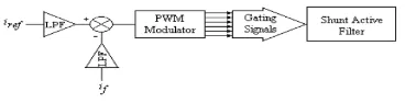
The synoptic diagram of the applied PWM comparator is shown in Fig.4. The difference between the active filter current and the reference current passes through a relay or a hysteresis comparator in order to determine the switches Si, Si' gating signals of each arm of the inverter. Here the modulating signal is compared with the carrier signal, at zero crossover points the signal pulses are generated, which the inverter power switches in a manner that reduces the current error.
Fig 4:PWM comparator synoptic diagram
c. CONTROL CIRCUIT
Figure 5 illustrates the active power filter control circuit synoptic diagram, where „PI‟ is a Proportional-Integrator corrector.
Fig 5: Active filter control circuit symbolic diagram
A good and robustness control is a system which forces a signal to track closely its reference. The control strategy applied in this paper is the carrier-based PWM modulation, which will be described later.
IV.FUZZY CONTROL APPLICATION OF THE ACTIVE POWER FILTER‟S CURRENT
Fuzzy logic serves to represent uncertain and imprecise knowledge of the system, whereas fuzzy control allows taking a decision even if we can‟t estimate inputs/outputs only from uncertain predicates.
The closed loop controller for SAF has an inner current control loop and outer voltage control loop. The outer voltage loop decides the magnitude of the reference current.
Fig 6: Control scheme of fuzzy Controller
V. SIMULATION RESULTS
For simulation studies, we used SIMULINK toolbox under MATLAB software in order to model and test the system.
The simulation parameters are summarized below in Table 1.
TABLE-1
a. SIMULINK DIAGRAM OF SAF WITH PI CONTROLLER
In order to reduce line harmonics, shunt active filters are used.SAF acts as a current source as it is connected in parallel with a non linear load and controlled to compensate the required compensation currents.Here,voltage source inverter is used as a SAF.SAF consists of a three phase voltage source inverter with current as regulation.VSI contains a three phase Isolated Gate Bipolar Transistors(IGBT‟s) with anti-paralleling diodes.VSI is connected in parallel with three phase supply through three inductors Lf1 ,Lf2,Lf3.DC side of VSI is connected to a DC capacitor, that carries input ripple current of the inverter. DC capacitor provides a constant DC voltage. The Lf1 ,Lf2,Lf3 perform voltage boost operation
in combination with the capacitor, and at same time act as low pass filter for AC source current. SAF must be controlled to produce the compensating currents following the reference currents through the control circuit. For this shunt active filter PI controller is applied. The capacitor voltage (Vc) is given to a low pass filter, which gives average capacitor voltage. The Vc is compared with nominal set point capacitor voltage and the error is processed using PI controller.
Fig 7: Simulink model of SAF with PI controller
Fig 8: Supply current waveform after applying PI SAF.
b. SIMULINK DIAGRAM OF SAF WITH FUZZY CONTROLLER
In order to reduce the harmonic distortion, fuzzy controller is applied to shunt active filter. The control scheme of Fuzzy control is the capacitor voltage (Vc) is given to a low pass filter, which gives average capacitor voltage. The Vc is compared with nominal set point capacitor voltage and the error is processed using FC controller. The output of controller is proportionality factor k.The reference currents are compared with filter actual currents and the error signal is compared with the triangular wave and is passed through hysteresis controller or relay or sliding mode control to generate the firing pulses which activate the inverter power switches in a manner that reduces the current error.
The main characteristics of the fuzzy control are,
Two input signals are capacitor voltage error and change in error are properly scaled and fuzzified.
Centroid method is empolyed for defuzzification.
The fuzzy rules are given in Table 2.
TABLE-2
Fig 9: Simulink model of SAF with Fuzzy controller
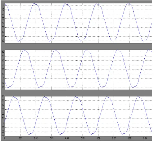
Fig 10:Supply current waveform after applying Fuzzy SAF
VI-CONCLUSION
Throughout this work, the effectiveness of the shunt active power filtering especially with the application of fuzzy logic controller. In fact, the distortion of the power supply current was diminished to a satisfactory level. The harmonics present in the source current are compensated by developing a suitable switching pattern for the active filter..The control of distortions by proper switching is first simulated by the conventional PI controller. When the PI controller is employed the source current shaping is achieved along with the significant amount of spikes.Therefore,a mamdani type fuzzy logic controller is used for multiple non linear loads to limit the line current distortion using three phase active power filter. In presence of fuzzy controller the source current shaping is achieved with negligible amount of spikes.
Thus, the proposed Fuzzy controller has better dynamic behavior than conventional PI control. It is proved that the fuzzy logic control yields the results, which are superior to those, obtained with the conventional controllers.Therefore,Fuzzy controller is characterized as an intelligent adaptive controller.
REFERENCES
1] C.Sharmeela,M.R.Mohan,G.Uma,J.Bhaskaran,”Fuzzy logic controller Based Three-Phase Shunt Active Filter for line Harmonics Reduction”. Journal of computer science 3(2):76-80,2007.
2] Hocine Benalla and Hind Djeghloud,”Shunt active filter controlled by fuzzy logic”,J.King Saud
Univ.,Vol.18,Eng.Sci(2),pp.231-247,Riyadh(1426h./2005)
3] Das, J. C. “Passive Filters: Potentialities and Limitations”. IEEE Trans. Ind. Applicat., 40, No. (2004),232-241.
Filters”. IEEE Trans. Ind. Applicat., 26, No. 6 (1990), 983-990.
5] Morán, L.A., Fernandez, L., Dixon, J.W. and Wallace, R. “A Simple and Low-cost Control Strategy for Active Power Filters Connected in Cascade”. IEEE Trans. Ind. Electron., 44, No. 5 (1997), 621-629.
6] Jintakosonwit, P., Akagi, H., Fujita, H. and Ogasawara, S. “Implementation and Performance of Automatic Gain Adjustment in a Shunt Active Filter for Harmonic Damping Throughout a Power Distribution System”. IEEE Trans. Power Electron., 17, No. 3 (2002), 438-447.
7] Dixon, J.W., Venegas, G. and Morán, L.A. “A Series Active Power Filter Based on a Sinusoidal Current-controlled Voltage-source Inverter”. IEEE Trans. Ind. Electron., l44, No. 5 (1997), 612-620.
8] Detjen, D. and Park, M.H. “A New Hybrid Filter to Dampen Resonances and Compensate Harmonic Currents in Industrial Power Systems with Power Factor Correction Equipment.” IEEE Trans. Power Electron., 16, No. 6 (2001), 821-827.
9] Lin, B.R. and Yang, T. Y. “Analysis and Implementation of a Three-level Active Filter with a Reduced Number of Power Semiconductors.” IEE Proc. Electric Power Applicat., 152, No. 5, (2005), 1055- 1064.
10] Dell'Aquila, A., Delvino, G., Liserre, M. and Zanchetta, P. “A New Fuzzy Logic Strategy for Active Power Filter.” IEE Conf. Publ. 8th Intern. Conf. Power Electron. and Variable Speed Drives, No. 475 (2000), 392-397.
11] Dell'Aquila, A., Lecci, A. and Monopoli, V.G. “Fuzzy Controlled Active Filter Driven by an Innovative Current Reference for Cost Reduction.” IEEE Intern. Symposium Ind. Electron. Proc., No. 3 (2002), 948-952. 12] Hamadi, A., Al-Haddad, K., Rahmani, S. and
Kanaan, H. “Comparison of Fuzzy Logic and ProportionalIntegral Controller of Voltage Source Active Filter Compensating Current Harmonics and Power Factor.” IEEE Intern. Conf. Ind. Techn., No. 2 (2004), 645-650.
13] Seguier, G. Electronique De Puissance: Les Fonctions De Base et Leurs PrincipalesApplications. 7th ed., Paris: Dunod, 1999.
14] Choe, G.-H. and Park, M.-H. “A New Injection Method for an AC Harmonic Elimination by Active Power Filter”. IEEE Trans. Ind. Electron., 35, No. 1 (1988), 141-147.