Article
Analysis and Application of a Novel Layered
Bidirectional Equalizer for Series Connected
Battery Strings
Shubiao Wang 1,2, Longyun Kang 1,2,*, Wenbiao Li 1,2, Xiangwei Guo 3, Zefeng Wang 1,2 and Ming Liu 1,2
1 New Energy Research Center, School of Electric Power, South China University of Technology, Guangzhou 510640, China; [email protected] (S.W.); [email protected] (W.L.); [email protected] (Z.W.); [email protected] (M.L.)
2 Guangdong Key Laboratory of Clean Energy Technology, School of Electric Power, South China University of Technology, Guangzhou 510640, China
3 College of Electrical Engineering and Automation, Henan Polytechnic University, Jiaozuo 454000, China; [email protected]
* Correspondence: [email protected]; Tel.: +86-137-2809-8863
Abstract: To eliminate the influence of the inconsistency on the cycle life and the available capacity of the battery pack, and improve the balancing speed, a novel inductor-based layered bidirectional equalizer (IBLBE) is proposed. The equalizer is composed of the bottom balancing circuits and the upper balancing circuits, and the two layer circuits both consist of a plurality of balancing sub-circuits, which allow the dynamic adjustment of equalization path and equalization threshold. The battery string is modularized by layered balancing circuits to realize fast active equalization, especially for long battery strings. By controlling the bottom balancing circuits, the individual cells can be balanced in each module. At the same time, the equalization between battery modules can be realized by controlling the upper balancing circuits. Simulation and experimental results demonstrate that the proposed equalizer can achieve fast active equalization for a long battery string, and has the characteristics of multi balancing path, large balancing current and high accuracy. The advantages of the proposed equalizer are further verified by a comparison with existing active equalizer.
Keywords: series connected battery string; layered bidirectional equalizer; power inductor; dynamic adjustment of equalization path
1. Introduction
Since the individual cell has limited voltage and capacity, power batteries require a variety of series or parallel combinations to achieve the voltage or capacity level for various applications [1][2].
However, due to the manufacturing inconsistency and unique performance characteristic of every single cell, the cells in series connected may suffer from serious imbalance between cell voltages or state of charge (SOCs) after several charging of discharging cycles, which can cause some of the cells to be overcharged or over discharged. This degrades the performance of battery strings, shortens its lifetime, and even poses a safety hazard (e.g., explosion or fire.etc.). Equalization for battery strings could be realized to prevent these phenomena and prolong the battery strings lifetime.
The passive equalization is the most straightforward and the cheapest one. However, the excess energy is converted into heat rather than be stored, which leads to the energy waste and thermal management problems.
The active cell balancing methods transfer energy from higher energy individual cell to lower energy cells. These active equalization circuits can generally be categorized as capacitors, converters or transformers circuits, each of which has its own advantages and disadvantages in terms of speed, accuracy, cost, and efficiency.
Daowd [1], Ye [5], Shang [6], and others have proposed several equalization circuit topologies based on switched-capacitors or LC quasi-resonant circuits, which charge or discharge capacitors to realize energy transfer. These equalization circuits can realize zero-voltage gap. However, these circuits suffer from a longer balancing time, especially with a small difference in cells voltages. Transformer-type equalization circuits have the basic structure of a fly-back transformer [1][14], which can be divided into a variety of types, such as single magnetic cores, multiple magnetic cores, single vice sides, and multiple vice sides. Transformer-type equalization circuits have the characteristics of high level of integration and high balancing speed but poor expandability and large transformer magnetic flux leakage.
Finally, converter-type equalization circuits use DC-DC converters for energy transfer, including buck, boost and Ćuk. The equalization circuits proposed by Lee [7], Yarlagadda [8], Phung [9], Lu [10], Chen [11], and Guo [12] belong to this type. Converter equalization circuits can realize bidirectional energy flow with higher balancing efficiency, but they often require a complex switch array and a precise control algorithm. Two of the most common inductor-based equalization circuits are the adjacent equalizer proposed in [9] and the single switched inductor equalizer proposed in [8]. As shown in figure 1(a), the inductor-based adjacent equalizer (IBAE) senses the voltage difference of the two neighboring cells, and transfers energy from the higher one to the lower one. Multiple balancing sub-circuits can operate at the same time, but it takes a relatively long time for transferring energy from the first one to the last one especially in the long battery string. Figure.1 (b) presents the single switched inductor equalizer (SSIE). The SSIE can achieve the direct cell-to-cell energy transfer between any two cells in the battery string. However, this equalizer has a complex switch matrix which needs to operate 4 switches in each switching period, and it takes a long time to serve all cells in a long battery string with only one balancing bypass.
(a) (b)
Figure.1 Two traditional inductor-based equalizers. (a) The inductor-based adjacent equalizer (IBAE); (b) The single switched inductor equalizer (SSIE).
lower energy cells in the discharging process. The proposed equalizer realizes dynamic equalization and preventing over-charge and over-discharge.
In this paper, the IBLBE is proposed and analyzed. Its circuit structure and equalization principle are introduced in Section 2. The models and calculation of the key parameters are derived in Section 3. In Section 4, the simulation results are presented. The experimental results and the advantages of IBLBE compared with the inductor-based adjacent equalizer are presented in Section 5, followed by the conclusion in Section 6.
2. Proposed Equalizer Scheme
2.1 Structure of the Proposed Equalizer
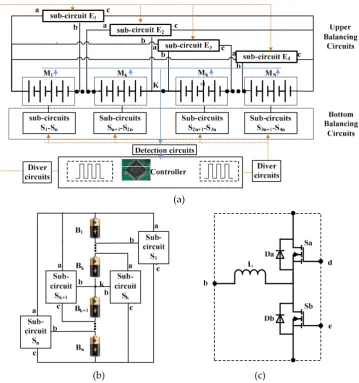
Figure 2 shows the system configuration of the proposed equalizer. Figure 2 (a) is the structure of the equalizer; figure 2 (b) is the schematic diagram of the bottom balancing circuit; figure 2 (c) is the schematic diagram of balancing sub-circuit.
The battery string connected in series is subdivided into N modules, and each module contains n individual cells. The N battery modules are divided into two parts with cutoff point K. If N is an even number, n=2*K; if N is an odd number, n=2*K-1. Every battery module Mi is equipped with a balancing sub-circuit Ei, which controls the charge transfer between Mi and other modules. Each battery module is divided into two parts with cutoff point k. If n is an even number, n=2*k; if n is an odd number, n=2*k-1. Every individual cell is equipped with a balancing sub-circuit Sj, which controls the charge transfer between Bi and other individual cells in this module.
The balancing sub-circuits Ei and Si are implemented by buck-boost converters, which allow the bidirectional energy flow. The balancing sub-circuits Ei compose the upper balancing circuits, which are used to achieve the equalization between battery modules. The balancing sub-circuits Si compose the bottom balancing circuits which are used for equalization between cells in each module.
The proposed equalizer IBLBE can achieve the dynamic adjustment of equalization path and equalization threshold, described as follows:
(1) Dynamic adjustment of the equalization path.
In the equalization process, the balancing sub-circuit Ei provides equalization path for module
Mi, and the balancing sub-circuit Sj provides equalization path for individual cell Bj. Furthermore,
the equalizer can extend the equalization path by operating Ei and Sj concurrently.
(2) Dynamic adjustment of equalization threshold.
The equalization circuits have two equalization threshold; one for the battery modules and the other for the individual cells in the same module. If the two thresholds are not met, the balancing circuits stop working.
The working condition for Ei is V( ) − V( ) > 5 V, V( )s are the modules terminal voltages.
In every battery module, the working condition for Sj is V( ) − V( ) > 3 V, V( )s are the terminal voltages of cells in the same module.
(a)
(b) (c)
Figure 2. System configuration of the proposed equalizer (a) Structure of the proposed equalizer (b) Schematic diagram of bottom balancing circuit (c) Schematic diagram of balancing sub-circuit
2.2 Equalization principle
The battery strings have four different working states: charging state, discharging state, the idle state after charging and the idle state after discharging. The equalization principles of charging state and the idle state after charging are the same; the equalization principles of discharging state and the idle state after discharging are the same.
L1 L2 S2b S1b L3 L4 S1a
S3a S3b
S4b S4a S2a L5 L6 S6b S5b L7 L8 S5a
S7a S7b
S8b S8a S6a L9 L10 S10b S9b L11 L12 S9a
S11a S11b
S12b
S12a
S10a
B1 B2 B3 B4 B5 B6 B7 B8 B9 B10 B11 B12
L13 L14 S14b S13b L15 L16 S13a
S15a S15b
S16b
S16a
S14a
B13 B14 B15 B16
L17 S17b S17a L18 S18b S18a L19 S19b
S19a L
20
S20b
S20a
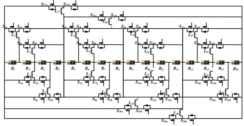
Figure 3. Proposed equalizer for 16 cells in series
2.2.1The equalization principles of charging state
In the charging state or the idle state after charging, firstly, identify the highest cell voltage; secondly control the corresponding sub-circuit Sj to transfer energy from highest cell to the other
cells (in the same module). Suppose that the cell voltage of B1 is higher than the others in the module M1. The equalization principle can be divided into the following two stages:
Stage 1: L1 charging
As shown in figure 4 (a), the individual cell B1 charges the inductor L1 when the switch S1a is
turned ON. The inductor L1 stores energy with the current gradually increasing. Some of the
electrical energy is transferred into magnetic energy stored in the inductor.
= + 0 < ≤ (1)
in which the circuit total resistance when S1a is turned ON, including the DC resistance of
L1,the turn-on resistance of S1a, and the internal resistance of cell B1. is the current of inductor L1,
is the turn-on time of S1a.
The general solution of is:
= − = 1 − 0 < ≤ (2)
The turned-on time t of S1a determines the peak value of inductor current i , which is a key parameter to calculate the average current of inductors and the average balancing current of balancing sub-circuits.
= 1 − , = (3)
In this process, L1 stores energy and the balancing sub-circuit S1 decreases the charging current of B1.
= − (4)
In which iB1 is the current through B1, is the charging current of battery string, is the
equalization current of balancing sub-circuit S1.
As shown in figure 4 (b), the inductor L1 charges cell B2, B3 and B4 in M1 through the flywheel
diode of S1b when the switch S1a is turned OFF, realizing the energy transfer from cell B1 to the other
cells.
This is a first order full response circuit, and the inductor current response is:
= ( ) − + 1 − ( ) < ≤ (5)
= ( + + ) ( ) − + < ≤ (6)
is the forward voltage of the (body diode of ), is the loop total resistance,
is the total terminal voltage of , and , is the stop time of L1 discharging.
In this process, the inductor L1 charges 、 、 through the flywheel diode of switch
and the balancing sub-circuit increases the charging current of 、 、 .
= = = + (7)
, , are the current through 、 、 respectively, is the equalization current of balancing sub-circuit .
S1a
B1
B2
B3
B4
L1 S1b
ic1
id1
S1
S1a
B1
B2
B3
B4
L1 S1b
S1
Ich Ich
(a) (b)
Figure 4. Equalization principles of proposed equalizer in charging state or the idle state after charging (a)Cell B1 charges inductor L1 (b)Inductor L1charges the cell B2,B3 and B4.
2.2.2 Equalization principles of discharging state
In the discharging state or the idle state after discharging, firstly, identify the lowest cell voltage; secondly control the corresponding sub-circuit Sj to transfer energy from the other cells (in
the same module) to the lowest voltage cell. Suppose that the cell voltage of B3 is lower than the others in the module M1. The equalization principle can be divided into the following two stages:
Stage 1: L3 charging
As shown in figure 5 (a), the individual cell B1 and B2 charge the inductor L3 when the switch
S3a is turned ON. The inductor L3 stores energy with the current iL3 increasing. Some of the electrical
energy is transferred into magnetic energy stored in the inductor. The balancing sub-circuit S3 increases the discharging current of cell B1 and B2.
= = + (8)
Stage 2: L3 discharging
As shown in figure 5 (b), the inductor L3 charges cell B3 in M1 through the flywheel diode of
switch when the switch S3a is turned OFF, realizing the energy transfer from cells B1 and B2 to
the cell B3. The balancing sub-circuit S3 decreases the discharging current of cell B3.
(a) (b)
Figure 5. Principle of proposed equalizer in discharging or the idle period after discharging (a)B1 and B2 charge inductor L3 (b) L3 charges the cell B3.
2.3 Module equalization principle
In a long battery string, it needs more equalization path working simultaneously to improve the balancing speed.
The proposed equalizer modularizes the battery string with layered bidirectional balancing circuits. The balancing sub-circuits Ei in upper layer circuits are operated simultaneously with the sub-circuits Sj in the bottom layer, which extends the balancing path and can achieve the fast equalization between modules.
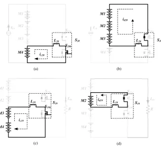
In the charging state or the idle state after charging, the energy is transferred from the highest voltage module to the others. When the voltage of module M4 is higher than the others, the operation can be divided into two stages.
As shown in figure 6 (a), the M4 charges the inductor L20 when the switch S20b is turned ON.
Then, the inductor L20 charges the module M1, M2 and M3 though the flywheel diode of S20a when
the switch S20b is turned OFF, shown in figure 6 (b).
In the discharging state or the idle state after discharging, the energy is transferred from the other modules to the lowest voltage one. When the voltage of module M2 is lower than the others, the operation can be divided into two stages.
As shown in figure 6(c), the module M3 and M4 charge the inductor L19when the switch S19b is
turned ON. Then, the inductor L19charges the module M2 though the flywheel diode of S19awhen
L20
S20b
ic20
S20
M4
L20 S20
M1
M2
M3
id20
M3
M4
L19
S19b
S19 M2 L19 S19
ic19
id19
(a) (b)
(c) (d)
Figure 6. Modules equalization principles. (a) M4 charges L20. (b) L20 charges modules M1, M2 and
M3 .(c) M3 and M4 charge L19 (d) L19 charges module M3.
3. Modeling, Analysis and calculation of the key parameters
In this section several key parameters are analyzed including the balancing speed, the balancing current, the inductors current, the duty cycle of switch waveform, the switching frequency and the inductances.
3.1 Modeling of inductor current and duty cycle of driving waveform
DC-DC converters have two working modes: continue current mode (CCM) and discontinuous current mode (DCM), shown in figure 7. Considering the magnetic saturation and safety allowance, DC-DC converters have to work in the DCM, where the inductors can release all absorbed energy in the off-time of the switches.
(a) (b)
Figure 7. Two operating mode of DC-DC converter (a) Continuous current mode (CCM) (b) Discontinuous current mode (DCM)
During the energy transfer process of the inductor , denote the voltage across by when the switch is turned ON, namely the total cells voltage charging ; denote the voltage across
= + 0 < ≤ (10)
= + − < ≤ (11)
Ignore the resistance since its value is very small. Then the inductor current increases linearly when the switch is turned ON:
= ∙ (0 < < ) (12)
When the switch is turned OFF, ignore the resistance and forward voltage of flywheel diode, the inductor current decreases linearly:
= − ∙ ( − ) ( < < ) (13)
= ∙ = ∙ ∙ (14)
=
, 0 ≤ <
− ( − ) , ≤ <
0 , ≤ ≤
(15)
in which D represents duty cycle,and T represents switching period.
To make the DC-DC converters working in the DCM, the inductor current need drop to 0 in the off-time of switch. The conditions that the duty cycle need satisfy are derived as follows:
= 0 when = ; since > , when =
− ( − ) < 0 (16)
Furthermore,
D <
+ =
1 1 +
(17)
In the equalization process, the duty cycle of driving waveforms for balancing sub-circuits Ei and Sj are the same.
In the equalization for charging state or the idle state after charging, the balancing circuits transfer energy from the individual cell with highest voltage to the others, so:
= (18)
=
, 1 ≤ ≤
, < ≤ n
< 1
1 +V + V + VV , = 1
< 1
1 +V + VV , = 2
< 1
1 +V + VV , = 3
< 1
1 +V + V + VV , = 4
(20)
In the equalization for discharging state or the idle state after discharging, the balancing circuits transfer energy from the other cells to the lowest voltage cells, so:
=
, 1 ≤ ≤
, < ≤ n
(21)
= (22)
< 1
1 +V + V + VV , = 1
< 1
1 +V + VV , = 2
< 1
1 +V + VV , = 3
< 1
1 +V + V + VV , = 4
(23)
3.2 Inductance, switching frequency and equalization speed
There is a key indicator for equalizer need to be considered: the cell-balancing time. This problem can be solved by increasing the balancing current. This is because the amount of charges transferred from one cell to others in unit time is proportional to the average value of current through the cell [5].
∆Q = ∙ T ∙ (24)
In which, ∆Q is the energy transferred from one cell to the others in one second, is the average current through , T is the switching period and is the switching frequency.
In equalization process, the current in balancing circuit is derived as follows: The peak value of inductor current
= = (25)
The average value of inductor current
=1
In equalization for charging state or the idle state after charging, the average value of current through cell and module Mi are:
=1 2 V
(27)
=1 2 V
(28)
The average current value of cells/modules are proportional to the product of and V /V and is inversely proportional to the product of and . The values of and V /V cannot adjust at will, in that case, the selection of and can achieve different effects on the balancing current and balancing speed.
4. Simulation Result
The simulation model of the proposed equalizer is built in PSIM9.0.
In order to reduce the balancing time, sixteen 1F capacitors are employed to substitute cells with initial voltage shown in table 1. The switching frequency is set as 10 kHz. The inductances in Si
are 100uH, and the inductances in Ei are 330uH. It is assumed that the capacitors, inductors and
switches are all lumped element. Moreover, the influence of parasitic inductance and parasitic capacitance and the deviation generated by AD transfer are ignored. The active condition set for balancing sub-circuit is V( ) = V( ) > V( ) + 5mV, i = 1,2,3,4. The active condition set for balancing sub-circuit is V( ) = V( ) > V( ) + 3mV, j = 1,2, … ,16, where V(B)max and V(B)min are the cells voltage in the same module.
Table 1 Initial voltage of 16 cells.
Modules VM1 VM2 VM3 VM4
Voltage(V) 15.027 15.153 15.201 15.301
Cells VB1 VB2 VB3 VB4 VB5 VB6 VB7 VB8
Voltage(V) 3.771 3.833 3.698 3.725 3.849 3.834 3.751 3.719 Cells VB9 VB10 VB11 VB12 VB13 VB14 VB15 VB16 Voltage(V) 3.738 3.803 3.807 3.723 3.834 3.850 3.795 3.822
VBmax=3.850V, VBmin=3.698V,maximum voltage gap is 0.152V. VMmax=15.301V, VMmin=15.027V, maximum voltage gap is 0.274V.
4.1 Equalization simulation for charging state or the idle state after charging.
Figure 8 shows the equalization simulation results of charging state with a 0.5A charging current. The equalization between modules is achieved at 0.035s and the cell-balancing stops at 0.234s, with the final voltage gap 4mV.
0 0.1 0.2 0.3
Time (s) 3.7
3.75 3.8 3.85 3.9 3.95 4
0 0.1 0.2 0.3
Time (s) 15
15.2 15.4 15.6 15.8 16
VM1 VM2 VM3 VM4
Figure 8. Equalization simulation results of proposed equalizer for 16cells during charging process.(a)16cells voltage trajectories (b) 4 modules voltage trajectories.
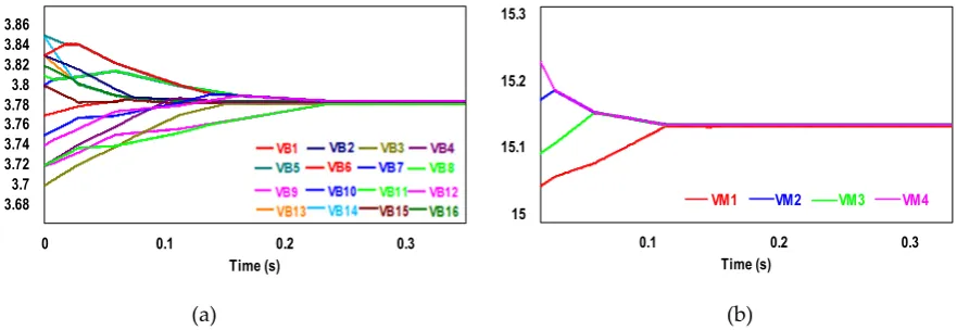
Figure 9 shows the simulation result of equalization for the idle state after charging. Firstly, the equalization between modules is achieved at about 0.113s. Then, the equalization stops at 0.238s, and the final voltage gap is 4mV.
0.1 0.2 0.3
Time (s) 15
15.1 15.2 15.3
0 0.1 0.2 0.3
Time (s) 3.68
3.7 3.72 3.74 3.76 3.78 3.8 3.82 3.84 3.86
VM1 VM2 VM3 VM4
(a) (b)
Figure 9. Equalization simulation results of proposed equalizer for 16cells during idle period after charging (a)16cells voltage trajectories (b) 4 modules voltage trajectories.
4.2 Equalization simulation for charging state or the idle state after charging.
Figure 10 shows the equalization simulation results of discharging state with a 0.5A discharging current. The module equalization is achieved at about 0.213s and the cell balancing stops at 0.267s, with the final voltage gap 4mV.
0 0.1 0.2 0.3
Time (s) 3.6
3.65 3.7 3.75 3.8 3.85
0 0.1 0.2 0.3
Time (s) 14.4
14.6 14.8 15 15.2
15.4 VM1 VM2 VM3 VM4
(a) (b)
Figure 10. Equalization simulation results of proposed equalizer for 16cells during discharging process (a)16cells voltage trajectories (b) 4 modules voltage trajectories.
0 0.1 0.2 0.3 Time (s) 3.68 3.7 3.72 3.74 3.76 3.78 3.8 3.82 3.84 3.86
0 0.1 0.2 0.3
Time (s) 15 15.05 15.1 15.15 15.2 15.25 15.3
VM1 VM2 VM3 VM4
(a) (b)
Figure 11. Equalization simulation results of proposed equalizer for 16cells during idle period after discharging. (a) 16cells voltage trajectories (b) 4 modules voltage trajectories.
4.3 Comparative study with typical inductor-based equalizers
In order to validate the advantages in balancing speed of the proposed equalizer, comparative studies with traditional inductor-based adjacent equalizer (IBAE) and single switched inductor equalizer (SSIE) are implemented. In the comparative simulation, the initial cells voltages are the same with previous simulation shown in table 1; the inductances are 100uH; the switching frequency is 10 kHz; the duty cycle is 48%.
The topologies of IBAE and SSIE are shown in figure 1.
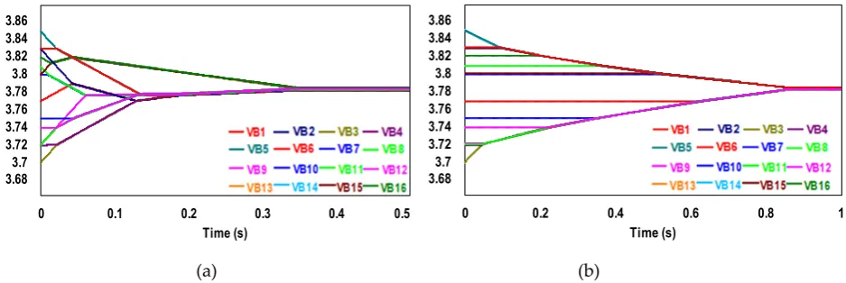
The equalization simulation results of traditional inductor-based equalizers (IBAE and SSIE) for 16cells during idle state is given in figure 12. When the IBAE achieves the same 4mV voltage gap, its balancing time is 0.347s. The SSIE achieves the same 4mV voltage gap at about 0.851s.
The proposed equalizer achieves cells balancing at about 0.238s in the idle state after charging. It reduces the balancing time by 31.4% compared with the IBAE (0.347s) and reduces the balancing time by 72% compared with SSIE (0.851s).
0 0.1 0.2 0.3 0.4 0.5
Time (s) 3.683.7 3.72 3.74 3.76 3.78 3.8 3.82 3.84 3.86
0 0.2 0.4 0.6 0.8 1
Time (s) 3.68 3.7 3.72 3.74 3.76 3.78 3.8 3.82 3.84 3.86
(a) (b)
Figure 12. 16cells voltage trajectories in static equalization of contrast experiment (a) IBAE (b) SSIE
5. Experimental results
In order to further verify the equalization principles and show the balancing performance of the proposed equalizer, a balancing system is implemented and tested for sixteen 2.6 Ah Sanyo ternary lithium batteries.
Table 2 summarizes the parameters of IBLBE. The inductances and the resistances in Table 2 are measured by a TH2810D LCR Meter.
The standing time in every equalization cycle is aimed at eliminating the polarization voltage of cells. Therefore, it is more accurately to test the real open-circuit voltages (OCVs) of cells, and issue the balancing instructions.
Table 2 Component Values used for the equalizer
Parameters Values
Battery string Sanyo ternary
lithium batteries B1-B16 2.6Ah
Equalizer MOSFET S1a, S1b-S20a, S20b IRF530 RDS(on)<0.090Ω
Diode D1a,D1b-D20a,D20b VD<0.6V
Inductance L1-L16 99.1-101.5μH R<0.1450 Ω
L17-L20 328.2-332.4μH R<0.3022 Ω
5.1 Equalization for charging state
The battery string charging current is 0.5A. The initial voltage of cells and modules is shown in table 1.The balancing circuits S2, S5, S11, S14 and E4 operate in the beginning.
Figure 13 (a) shows the experimental waveforms of inductor current iL11 and iL20. The duty cycle
of PWM is 65%. The inductor current is discontinuous and varies in saw-tooth waveform. The peak value of iL11 comes to 1.7A, and the peak value of iL20 is 1.8A.
(a) (b)
Figure 13. Experimental waveform of inductors current (a) iL11 and iL20 in equalization for charging state (b) iL3 and iL17 in equalization for discharging state
Figure 14 shows the 16 cells voltage trajectories in equalization during charging process. The initial voltage gap shown in table 1 is 152mV, and it decreases to 3mV at about 3197s.
Table 3 presents 16 cells voltage before and after equalization in charging and discharging state.
Table 3. 16cells voltage before and after equalization in charging and discharging state
5.2 Equalization for discharging state
In discharging process, the discharging resistor is 150Ω. The balancing sub-circuits S3, S8, S12, S15 and E1 operate in the beginning. Figure 13 (b) presents the experimental waveforms of inductors current iL3 and iL17. The duty cycle of PWM is 24%. The inductor current is discontinuous
and varies in saw-tooth waveform. The peak value of iL3 comes to 1.8A, and the peak value of iL17 is
1.9A.
Figure 15 shows the 16 cells voltage trajectories in equalization during discharging process. The initial voltage gap shown in table 1 is 152mV, and it decreases to 3mV at about 3098s.The final voltages of 16 cells after equalization are shown in table 3.
Figure 15. 16 cells voltage trajectories in equalization for discharging state
6. Conclusion
In this paper, a novel inductor-based layered bidirectional equalizer for series connected battery strings is proposed. The equalization principle, modeling of balancing current, the 16 cells-balancing performance and the comparative studies are presented. Adjusting the product f*L
3.771 3.833
3.698 3.725
3.849 3.834
3.751
3.719 3.738
3.803 3.807
3.723
3.834 3.850
3.795 3.822 3.945 3.945 3.942 3.945 3.945 3.945 3.946 3.942 3.945 3.945 3.946 3.942 3.945 3.945 3.942 3.945
3.624 3.627 3.624 3.624 3.627 3.624 3.624 3.624 3.624 3.624 3.627 3.624 3.625 3.627 3.624 3.625
3.300 3.400 3.500 3.600 3.700 3.800 3.900 4.000 4.100
VB1 VB2 VB3 VB4 VB5 VB6 VB7 VB8 VB9 VB10 VB11 VB12 VB13 VB14 VB15 VB16
VB
(
V
)
Initial voltage
of switching frequency and inductance can achieve the different levels of balancing current and balancing speed. Comparative simulations with two typical inductor-based equalizers (IBAE and SSIE) are implemented. The proposed equalizer reduces the balancing time by 31.4% compared with the IBAE and reduces the balancing time by 72% compared with SSIE. The simulation and experimental results show that the proposed equalizer can decrease the charging current of higher voltage cells during charging process and reduce the discharging current of lower voltage cells during discharging process; the equalizer can transfer energy from higher voltage cells to the lower voltage cells in the idle period after charging or discharging. Moreover, the layered balancing circuits extend the balancing path and increase the balancing current, which allow fast and active equalization especially for a long battery string. As a future work, the proposed topology will be used in battery strings in energy storage and EVs.
Acknowledgments: This work is supported by the DongGuan Innovative Research Team Program (No. 2014607119) and the Guangdong Province Science and Technology Program (No. 2014B010125002). I would like to express my deepest gratitude to my supervisor, Longyun Kang, who has provided me with valuable guidance at every stage of this paper-writing. I would also like to thank the anonymous reviewers for dedicating the time to review my paper despite their busy schedules.
Author Contributions: This research article has five authors. The circuit structure was designed by Shubiao Wang and Longyun Kang. Shubiao Wang, Longyun Kang , Xiangwei Guo and Ming Liu conceived the research methods and control strategies. Shubiao Wang, Wenbiao Li, and Zefeng Wang designed and performed the experiments. Longyun Kang contributed the experimental environment. Shubiao Wang wrote the paper.
Conflicts of Interest: The authors declare no conflicts of interest.
References
1. Daowd, M.; Omar, N.; Bossche, P. V. D.; Mierlo, J. V. A review of passive and active battery balancing based on matlab/simulink. International Review of Electrical Engineering. 2011, 6(7), 2974-2989.
2. Kobzev G A. Switched-capacitor systems for battery equalization. Modern Techniques and Technology, 2000. MTT 2000. Proceedings of the VI International Scientific and Practical Conference of Students, Post-graduates and Young Scientists. 2000. pp. 57-59
3. A. Thomas. Stuart; Wei Zhu. Fast Equalization for Large Lithium Ion Batteries. IEEE Aerospace and Electronic Systems Magazine. 2009, 24, 27-31.
4. Zhang X; Liu P; Wang D. The Design and Implementation of Smart Battery Management System Balance Technology. Journal of Convergence Information Technology. 2011, 6(5), 108-116.
5. Ye Y; Cheng K W E. Modeling and Analysis of Series–Parallel Switched-Capacitor Voltage Equalizer for Battery/Supercapacitor Strings. Emerging & Selected Topics in Power Electronics IEEE Journal. 2015, 3(4), 1-1. 6. Shang, Y.; Zhang, C.; Cui, N.; Guerrero, J. M. A cell-to-cell battery equalizer with zero-current switching
and zero-voltage gap based on quasi-resonant LC converter and boost converter. IEEE Transactions on Power Electronics. 2015. 30(7), 3731-3747.
7. Lee, Y.S.; Cheng, M.W. Intelligent control battery equalization for series connected lithium-ion battery strings. IEEE Trans. Ind. Electron. 2005, 52, 1297–1307.
8. Yarlagadda, S.; Hartley, T.T.; Husain, I. A Battery Management System Using an Active Charge Equalization Technique Based on a DC/DC Converter Topology. In Proceedings of the 2011 IEEE Energy Conversion Congress and Exposition (ECCE), Phoenix, AZ, USA,17–22 September 2011; pp. 1188–1195. 9. T. H. Phung; J. C. Crebier; A. Chureau; A. Collet; N. T. Van Nguyen. Optimized Structure for Next-to-Next
Balancing of Series-Connected Lithium-ion Cells. 26th Annual IEEE Applied Power Electronics Conference and Exposition (APEC), 2011. pp.1374-1381.
10. Lu, X.; Qian, W.; Peng, F.Z. Modularized Buck-Boost + Cuk Converter for High Voltage Series Connected Battery Cells. In Proceedings of the 2012 Twenty-Seventh Annual IEEE Applied Power Electronics Conference and Exposition (APEC), Orlando, FL, USA, 5–9 February 2012; pp. 2272–2278.
12. Xiangwei Guo; Longyun Kang; Zhizhen Huang; Yuan Yao; Huizhou Yang. Research on a Novel Power Inductor-Based Bidirectional Lossless Equalization Circuit for Series-Connected Battery Packs. Energies
2015, 8, 5555-5576.
13. Lotfi, N.; Fajri, P.; Novosad, S.; Savage, J.; Landers, R. G.; Ferdowsi, M. Development of an experimental testbed for research in lithium-ion battery management systems. Energies, 2013, 6(10), 5231-5258.
14. Einhorn M; Guertlschmid W; Blochberger T. A current equalization method for serially connected battery cells using a single power converter for each cell. IEEE Transactions on Vehicular Technology. 2011, 60(9), 4227-4237.
15. Xiaojun,Tan. Battery management systems on Power Batteries: Applied Technology and Advanced Theories. Zhongshan University Press: GuangZhou, China, 2014; pp.79-108.
16. J. G.-Lozano; E. R. Cadaval. Battery equalization active methods. Power Sources, 2014, 246, 934–949.