MODELING AND SIMULATION OF THREE-PHASE
INDUCTION MACHINE IN STATIONARY
REFERENCE FRAME USING MATLAB SIMULINK
Rajesh Kr Ahuja
1, Sushil Verma
21,2
Department of Electrical Engineering,
YMCA University of Science & Technology, Faridabad(India)
ABSTRACT
This paper presentssimulation and analysis of three-phase induction machine in stationary reference frame
using MATLAB Simulink There is seldom a need for simulation andanalysis of an induction machine in the
arbitrary rotating reference frame. For power system studies, induction machine loads, along with other types of power system components, are often simulated on a system’s synchronously rotating reference frame. But for
transient studies of adjustable-speed drives, it is usually more convenient to simulate an induction machine and
its converter on a stationary reference frame.
Keywords: Induction Machine, Matlab, Modeling, Simulation, Stationary
Nomenclature:
Vds, Vqs -three-Phase supply voltages in d-q reference frame, respectively.
ids, iqs -three-Phase stator currents in d-q reference frame, respectively.
, -three-Phase stator flux linkages in d-q reference frame, respectively.
Vdr, Vqr -three-Phase rotor voltages in d-q reference frame, respectively.
idr, iqr -three-Phase rotor currents in d-q reference frame, respectively.
, -three-Phase rotor flux linkages in d-q reference frame, respectively.
rs, rr -stator and rotor resistances of machine per phase, respectively.
xls, xlr -leakage reactance of stator and rotor windings, respectively.
ωe ,ωr -supply and rotor angular frequency (electrical speed), respectively.
Tem, Tmech -electromagnetic and mechanical torques, respectively.
P -number of poles.
d -direct axis
q -quadrature axis
s -stator variable
r -rotor variable
I INTRODUCTION
The induction motor, which is the most widely used motor type in the industry, has been favoured because of its
good self-starting capability, simple and rugged structure, low cost and reliability. Along with variable
frequency AC inverters, induction motors are used in many adjustable speed applications which do not require
fast dynamic response. A synchronously rotating reference frame is used for small-signal dynamic stability
analysis about some operating condition, which yields steady values of steady-state voltages and currents under
balanced conditions. Since we have derived the equations of the induction machine for the general case that is in
the arbitrary rotating reference frame the equations of the machine in the stationary reference frame can simply be obtained by setting the speed of the arbitrary reference frame, ω, to zero. The variables in the stationary
reference frame are represented by a superscript ‘s’.
In recent years the control of high-performance induction motor drives for general industry applications and
production automation has received widespread research interests. Induction machine modelling has
continuously attracted the attention of researchers not only because such machines are made andused in largest
numbers but also due to their varied modes of operation both under steady and dynamic states. In an electric
drive system the machine is a part of the control system elements.
II INDUCTION MACHINE EQUATIONS IN STATIONARY REFERENCE FRAME:
Stator and rotor voltage equations:
(1)
Flux linkage equations:
(2)
Torque equation:
ω
ω (3)
III INDUCTION MACHINE IN STATIONARY REFERENCE FRAME 3.1 Simulation of an induction machine in the stationary reference frame
Now it is explained that how the developed model can be used to simulate a three-phase, p-pole, symmetrical
electrical machine in the stationary reference frame. We start by considering the equations of its input voltages
for the given neutral connections of the stator and rotor windings. The three applied voltages to the stator
terminals, , , and , need not be balanced for sinusoidal. In general, the three stator voltages are:
(4)
(5)
In simulation, the voltage, , can be determined from the flow of phase currents in the neutral connection, that
is:
(6)
Where and are the resistance and inductance of the connection between the two neutral points, s and g.
Clearly, when input s is solidly connected to point g, that is the connection impedance is zero, will be zero.
Equation (5) indicates that the voltage, , is also zero when the zero sequence components of the source and
stator phase voltages are both zero, as in a balanced operation of a symmetrical induction machine with a
balanced set of applied voltages that are sinusoidal and balanced. That will be zero for
balanced operation can be reached using the fact is zero in Equation (1).
We know that, a three wire connection between supply and stator windings is quite common. With a three wire
connection, the stator zero-sequence current, , equal to , is zero by physical constraint ,
irrespective of whether the three phase currents are balanced or not. Even though the sum of the phase currents
is constrained by the physical connection to be zero, the phase currents may be unbalanced, as in the single
phasing situation where the a-phase is open and . But, the free-floating stator neutral voltage, ,
may not be zero, depending on whether the applied voltages are sinusoidal and balanced.
Where the applied voltages are non-sinusoidal, as from the output voltages of a six-step inverter, the zero sequence components of the applied voltages may not be zero. Where the stator winding’s neutral is
free-floating, the voltage, , can be determined in simulation using Equation (6) with and set as high
as possible to approximate the actual open-circuit condition.
Now consider the transformation of stator phase voltages to dq0 stationary voltages. With the q-axis of the
stationary dq reference always aligned with the stator a-phase axis and a ω of zero, we can obtain the following relationships by setting θ to zero in the transformation matrix:
(7)
The qd0 voltages at both the stator and rotor terminals, referred to the same stationary qd0 reference frame, can
stationary qd0 frame to obtain the corresponding qd0 currents in the stationary reference frame. Usually,
stationary qd0 stator and rotor currents are then transformed back to phase currents for use in other parts of
simulation. The stator abc phase currents can be determined from the stator qd currents using the inverse
transformation as given below.
(8)
Observe that the machine’s dq circuits have the same T-connections of inductors as in the equivalent circuit of
the single-phase transformer. As such, the same technique to handle the cut-set inductors in the single-phase
transformer simulation can be used here.
3.2 Base Quantities
Mainly, machine equations are expressed in terms of the flux linkages per second, ’s, and x’s, instead of λ’s and L’s. These are related simply by the base or rated value of angular frequency, ωb, that is
where ωb=2пfrated electrical radians per second, frated being the rated frequency in Hertz of the machine. With
complex waveforms these may be justification to using the peak rather than the rms value of the rated phase
voltage as the base value. The base quantities with peak rather than rms value of a P-pole, three-phase induction
machine with rated line-to-line rms voltage, Vrated, and rated volt-ampere, Srated, are as follows:
Base voltage
Base volt-ampere
Base peak current
Base impedance
Base torque
Where
The model equations of the induction machine in the stationary dq0 reference frame may be rearranged into the
following form for simulation.
ω
ω (9)
ω
ω
ω
ω (10)
ω ωω
ω
(11)
Where
(12)
And
(13)
The torque equation is
(14)
The equation of motion of rotor is obtained by equating the inertia torque to the accelerating torque, that is
ω
(15)
In Equation (15), is the externally-applied mechanical torque in the direction of the rotor speed and is
the damping torque in the direction opposite to rotation. The value of will be positive for motoring condition,
as in the case of an applied shaft torque from a prime mover.
When used in conjunction with Equation (9) and (10), the per unit speed, , needed for building the speed
voltage terms in the rotor voltage equations, can be obtained by integrating
ω ω ω
(16)
Often, the above equation of motion is written in terms of the inertia constant, H, defined as the ratio of kinetic
energy of the rotating mass at base speed to the rated power, that is:
ω
(17)
Expressed in per unit values of the machine’s own base power and voltage, Equation (16) can rewritten as
ω ω in pu (18)
Note the cross-coupling speed voltage terms between the parts of the q-axis and d-axis circuit simulation. The zero
IV SIMULATION RESULTS
The simulation has been performed using sim power system tool box in MATLAB/SIMULINK environment.All the above equations are modelled in Simulink which is shown in Fig.1.
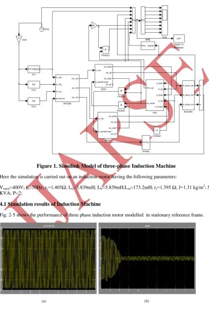
Figure 1. Simulink Model of three-phase Induction Machine
Here the simulation is carried out on an induction motor having the following parameters:
Vrated=400V; fb=50Hz; rs=1.405Ω; Lls=5.839mH; Llr=5.839mH;Lm=173.2mH; rr=1.395 Ω; J=1.31 kg/m2; Srated=4
KVA; P=2;
4.1 Simulation results of Induction Machine
Fig. 2-5 shows the performance of three phase induction motor modelled in stationary reference frame.
(c) (d)
(e) (f)
Figure 2. (a) stator phase to neutral voltage (b) stator current (c) developed torque (d) rotor speed in p.u. (e) developed power (f) stator rms current
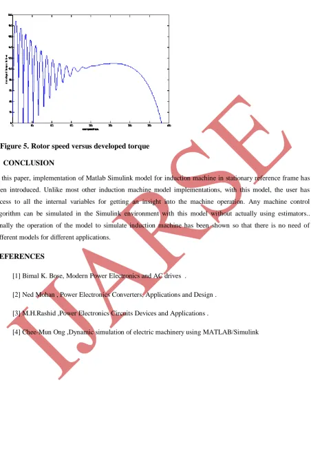
4.2 Characteristics curves
Figure 5. Rotor speed versus developed torque V CONCLUSION
In this paper, implementation of Matlab Simulink model for induction machine in stationary reference frame has
been introduced. Unlike most other induction machine model implementations, with this model, the user has
access to all the internal variables for getting an insight into the machine operation. Any machine control
algorithm can be simulated in the Simulink environment with this model without actually using estimators..
Finally the operation of the model to simulate induction machine has been shown so that there is no need of
different models for different applications.
REFERENCES
[1] Bimal K. Bose, Modern Power Electronics and AC drives .
[2] Ned Mohan , Power Electronics Converters, Applications and Design .
[3] M.H.Rashid ,Power Electronics Circuits Devices and Applications .
[4] Chee-Mun Ong ,Dynamic simulation of electric machinery using MATLAB/Simulink