Available online: https://edupediapublications.org/journals/index.php/IJR/ P a g e | 1676
MATLAB Based Grid Connected Single Phase Rooftop PV System
Dr kamaraju sir, P.Jithender M.tech , Kallepalli sravankumar M.tech , S.Venkatesh M.tech
Abstract—Nowadays renewable energy
sources are widely used such as wind energy and solar energy, due to their extreme abundance. So they should be properly interfaced with the power grid with suitable devices. In this paper a system of Photovoltaic (PV) proposes attractive alternative source of generation because these can be placed near to the load centers means we can place these systems on the top of our house roofs when compared with other renewable source of generation and can be easily interfaced to distribution systems. Maximum power point tracking topology is designed to extract the maximum power from solar panel. Generally rooftop PV system consists of battery backup and supports the off grid load efficiently without interruption of power but here a NPC three level inverter is implemented for injecting the real power of the renewable power into the grid to reduce the switching power loss,
harmonic distortion with single phase
synchronous reference frame (SRF) theory
based current controlled Pulse Width
Modulation (PWM) controller to realize maximum generated power evacuation by maintaining the DC link voltage constant without battery support, low THD sinusoidal line synchronized current output, and a capacitor connected parallel to input terminal of inverter provides the limited reactive power compensation based on the unutilized capacity of the inverter. Simulation results are observed to analyze the working of rooftop PV with proposed control algorithms in grid connected mode with limited reactive power conditioning under linear load conditions.
Index Terms—Photovoltaic (PV),
MPPT(Maximum power point tracking ),linear loads, , distribution system, THD(Total Harmonic Distortion), Pulse Width Modulation
(PWM), Reactive power compensation,
Synchronous reference frame
(SRF),Incremental Conductance (IC),
I INTRODUCTION
Renewable energy systems can provide clean, reliable, secure and competitive energy products and services to help meet the rapidly increasing global energy demand. In a Carbon constrained world of the future, renewable energy sources with zero net greenhouse gas emissions will have an increasingly important role to play. Being widely distributed, renewable energy sources have the potential to provide electric power, heating, cooling and vehicle transport fuels for the millions of people currently with limited or no access to them. Progress towards including the full externality costs relating to the use of fossil fuels in comparative economic analysis of energy supply systems, together with the rate at
which the costs of renewable energy
Available online: https://edupediapublications.org/journals/index.php/IJR/ P a g e | 1677
system and makes the system more stable with fewer harmonic. A NPC Three level inverter is developed and applied for injecting the real power of the renewable power into the grid to reduce the switching power loss, harmonic distortion, and electromagnetic interference caused by the switching operation of power electronic devices [2]. Since these sources have huge opportunity of generation near load terminal i.e. the source and load are very near to each other [3]. The rooftop application involving single phase DG‟s fed with PV source can be not only utilized for household use but the excess energy can be transferred to the grid through proper control scheme and adequate hardware. Control scheme based on instantaneous PQ theory has been presented in some literatures for single phase system [4]. Other control scheme such as synchronous reference frame (SRF) is mainly used with three phase system in which sinusoidal varying quantities are being transferred to dc quantities that provides better and precise control than PQ based control even under distorted condition of mains [5]. But SRF based control scheme can be customized for single phase which can‟t be utilized to get the desired dc quantity to generate required reference command. PV sources are interfaced with the grid through voltage source converters (VSC‟s). VSC‟s can be controlled either in PWM based voltage control method or hysteresis based current
controlled method (HCC). HCC based
controller gives fast response and better regulation but its major drawback lies with variable frequency. On the other hand the PWM based control gives fixed switching frequency that could be utilized easily for proper design of LC or LCL filters [6]. With PV sources connected at the DC side of the inverter, it is utmost essential to fetch
maximum power from the source to make the system efficient. Out of different algorithm to track maximum power point (MPP) such as perturb and observe (P&O), Incremental Conductance (IC) etc., IC based method provides fast dynamics and control over fast changing isolation condition [7] [8]. In this paper new control scheme based on SRF theory has been proposed for single phase rooftop PV grid connected system. An MPPT device is placed between the inverter and PV panel to extract the maximum power from the panel. Through the NPC Three level inverter the maximum tracked power is pumped into the grid through proper control on DC link voltage. By maintaining the DC link voltage constant during operation, is ensured the total power being generated by PV transferred across the DC bus by the inverter to the grid. Apart from active power transfer the system could be well utilized for providing limited reactive power compensation by using a capacitor connected to input inverter terminals based on available capacity of the NPC Three level inverter.
II SYSTEM CONFIGURATION
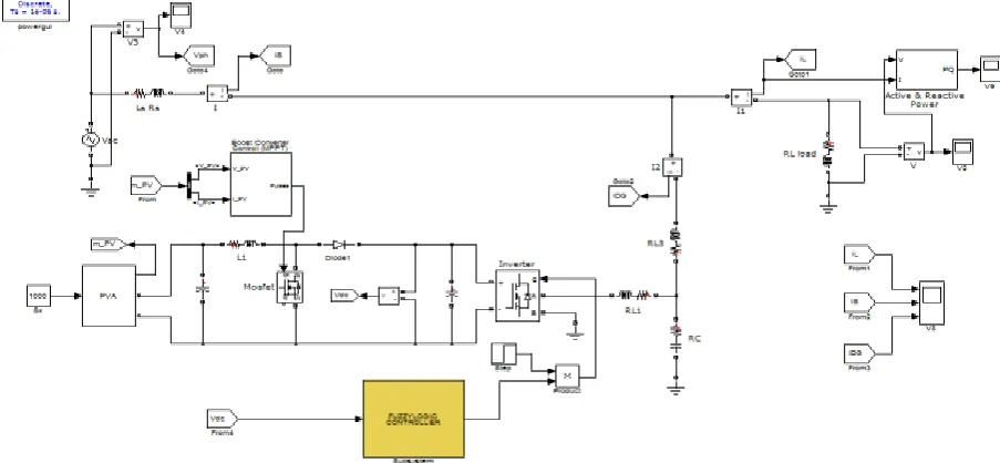
Figure depicts the schematic diagram of single phase grid connected PV system comprising PV panels, DC-DC converter, MPPT charge controller, tank capacitor, VSC and RL loads.
Fig 1 Block diagram for system configuration of PVDGCC
Available online: https://edupediapublications.org/journals/index.php/IJR/ P a g e | 1678
IC based MPPT controller is used to extract the maximum available power from the PV panels. Control based on tank capacitor voltage is used to control the transfer of maximum power to the grid via VSC. The direct voltage controlled current driven VSC keeps the voltage across the tank capacitor constant by regulating the power evacuation through voltage control. Proper design of LCL filter at the output of
VSC filters out harmonics at the PCC. The conventional 3 phase SRF theory is modified to suit the single phase system. The modified SRF theory is applied to decompose the load current to generate the reference reactive power current command. Reference for the real current component is obtained by applying PI controller on the error between measured voltage and the reference voltage.
6.1 MODELING OF PV ARRAYS
The basic equations that govern I-V characteristic of the ideal photovoltaic cell are reported in literatures. The typical equation governing the PV arrays is given as
Where, Vt= , Ns-Number of cells connected in series; Rp=Equivalent parallel Resistance; Rs=
Equivalent contact series Resistance. Commercially available KC200GT Kyocera make PV panels are considered here to design the array to deliver power of 800W by connecting 3 panels in a string and similar 2 strings in parallel in MATLAB Simulink. The parameters of the panel are shown in Table. The proposed charge controller operates to extract the maximum power at one level of solar insolation by using Incremental Conductance based MPPT controller
Fig:2 PV Panel model
6.2 CONTROL THEORY
The proposed system the 3 phase SRF based theory is modified for single phase system. The heart of the control scheme lays with correct estimation of phase voltage though phase locked loop
(PLL), which is used for generation of unit template vectors. The output of the PLL will be
Available online: https://edupediapublications.org/journals/index.php/IJR/ P a g e | 1679
shown in Fig. Using modified SRF theory both DG and load currents are transformed into d-q components and passed through low pass filter (LPF) to obtain only DC components corresponding to fundamental frequency as shown in Fig. 7.3. For such synchronized modified SRF theory based
transformation components corresponds to real and reactive power components
respectively. Assuming current reference as
The α-β component is then transformed to d-q using equations
Id and Iq obtained through transformation is passed though LPF to obtain the at DC quantities which after proper control on this DC quantity, it’s again converted back to α-β component using
After transformation only α component is used for signal generation. In the photovoltaic based grid connected system it is utmost important to extract MPP tracked power for economical operation and to avoid panels heating due to under utilization. To guarantee this, constant DC bus voltage is required to be maintained across DC link capacitor, and reference current is generated to obtain the command voltage reference for PWM control of the VSC as shown in Fig. The control forces
Available online: https://edupediapublications.org/journals/index.php/IJR/ P a g e | 1680
Fig. 3 Control Scheme for proposed System
reactive power component in load is
determined and multiplied with ‘k’ showing the selective or amount of power to be compensated as shown in Fig.. This reference reactive command is compared with DG ‘ qDG’ component and error is passed through PI controller to generate reference Vq *
component. This voltage reference d-q
component is then reverse transformed to α-β using equations (8). Out of the two components in stationary frame of reference vα * component is used for PWM gating signal generation.
The complete single phase grid connected PV system is simulated under MATLAB simulink
with RL load (R= 4 Ω, L= 4 mH) as shown in Fig.7.6. PV panels are connected in series and parallel in such a way that array could deliver maximum power of 8.5 kW at 1000 W/ insolation level. IC based MPPT algorithm is verified by writing embedded MATLAB code. LCL filter is connected at the output of VSC as per parameters given in the table II. The simulated results are studied to compute the performance of single phase grid connected system under limited available capacity of VSC. The parameters of the considered system are shown in Table-
Available online: https://edupediapublications.org/journals/index.php/IJR/ P a g e | 1681 6.4 PERFORMANCE EVALUATION
Single phase grid connected
photovoltaic based VSC with limited power conditioning is simulated under MATLAB
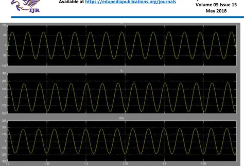
simulink environment. Fig. shows the
waveform for PCC voltage, source current, VSC current, load current, DC link voltage, MPPT power, and VSC output active and reactive power respectively. To make the analysis more clear initial transient conditions is not shown and analysis is started when sustained steady state is reached, i.e. starting from t =0.4s onwards. With PCC point voltage maintained at 230 V total load demand which is 55.16 A is shared between two sources – the grid source and the PV source connected at PCC as shown in Fig. Assuming capacity of VSC 10.5 KVA, and available MPP power of 8.5 kW at 1000 W/m2 insolation, its capacity is shared between active and reactive power output of VSC. Till t=1s when the insolation is at 1000 W/m2, the MPPT extracted 8.5 kW
Available online: https://edupediapublications.org/journals/index.php/IJR/ P a g e | 1682
Fig. 5 Dynamic response of single phase roof top PV system for voltage at PCC, source current from grid , VSC current, load current, DC link voltage , MPPT tracked power, Active and reactive power output of the VSC
Available online: https://edupediapublications.org/journals/index.php/IJR/ P a g e | 1683
Fig 7 Dynamic response of single phase roof top PV system for voltage at PCC, source current from grid , VSC current, load current, DC link voltage
Available online: https://edupediapublications.org/journals/index.php/IJR/ P a g e | 1684
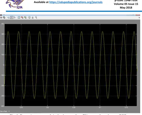
Fig. 9 Dynamic response of single phase roof top PV system for voltage at PCC Conclusion:
The complete single phase grid
connected PV system is simulated under MATLAB simulink with RL load (R= 4 Ω, L= 4 mH) as shown in Fig.6.8. PV panels are connected in series and parallel in such a way that array could deliver maximum power of 8.5 kW at 1000 W/ insolation level. IC based MPPT algorithm is verified by writing embedded MATLAB code. LCL filter is connected at the output of VSC as per parameters. The simulated results are studied to compute the performance of single phase grid connected system under limited available capacity of VSC.
CONCLUSION
The simulated results clearly
Available online: https://edupediapublications.org/journals/index.php/IJR/ P a g e | 1685
varying insolation conditions effectively. Such technique is envisaged to benefit the PV rooftop system and grid/microgrid by the limited compensation, thereby effectively utilizing the connected hardware.
REFERENCES
1. Velasco de la Fuente, D. ; Garcera, G. ; Figueres, E. ; Guacaneme, J.“Reconfigurable control scheme for a PV microinverter working in both grid connected and island modes,” IEEE Trans. Industrial Electronics,2012.
2. Jmjun Liu ;Jun Yang ;Zhaoan Wang "A New Approach For Single-Phase Harmonic Current Detecting And Its Applicationin in a Hybrid Active Power Filter," IEEE conf., 1999.
3. B. Singh, V. Verma, “,Selective compensation of power-quality problems through active power filter by current decomposition”IEEE Trans. Power delivery., vol. 23, no. 2, April 2008.
4. Guohong Zeng; Rasmussen, T.W.; Lin Ma; Teodorescu, R., “Design and control of
LCL-filter with active damping for Active Power Filter,” IEEE International Symposium on Industrial Electronics, pp. 2657-2562, 2010.
5. S.Mekhilef, "Performance of grid connected inverter with maximum power point tracker and power factor control," International Journal of Power Electronics, vol. 1, pp. 49-62, 2008.
6. S.Mekh Femia, N.; Petrone, G.; Spagnuolo, G.; Vitelli, M., “A Technique for Improving P&O MPPT Performances of Double-Stage Grid-Connected Photovoltaic Systems,” IEEE Trans. Industrial Electronics, vol. 56, pp. 4473-4482, 2009.
7. M. G. Villalava,j. r. Gazoli,E. Ruppert F., “Modelling and circuit –based simulation of Photovoltaic arrays” Brazilian Journal of Power Electronics,vol 14,no.4,pp. 35-45, 2009
8. B. Crowhurst, E.F. El-Saadany, L. El Chaar and L.A. Lamont "Single-Phase Grid-Tie Inverter Control Using DQ Transform for
Active and Reactive Load Power
Compensation," IEEE conf.,PECON,