Differential Fault Analysis of AES using a Single
Multiple-Byte Fault
Subidh Ali1, Debdeep Mukhopadhyay1, and Michael Tunstall2
1 Department of Computer Sc. and Engg, IIT Kharagpur, West Bengal, India. {subidh,debdeep}@cse.iitkgp.ernet.in
2 Department of Computer Science, University of Bristol, Merchant Venturers Building, Woodland Road,
Bristol BS8 1UB, United Kingdom. [email protected]
Abstract. In this paper we present an improved fault attack on the Advanced En-cryption Standard (AES). This paper presents an improvement on a recently pub-lished differential fault analysis of AES that requires one fault to recover the secret key being used. This attack requires that one byte entering into the eighth round is corrupted. We show that the attack is possible where more than one byte has been affected. Experimental results are described where a fault is injected using a glitch in the clock, demonstrating that this attack is practical.
1
Introduction
There are numerous methods for injecting a fault into a microprocessor, such as electromag-netic radiation, light, temperature variations, spikes in supply voltages and clock glitches [1]. Preventing all of these methods is becoming more and more complex for hardware designers. This problem is compounded by the ongoing scaling of devices to nano technologies where faults will be even harder to prevent. While these faults may have undesirable effects on normal applications, it can be totally disastrous for cryptographic systems. This was first noted by Boneh et al. [4], who observed that a single fault in one of the two exponentiations required to generate a RSA signature using the Chinese remainder theorem would allow an attacker to retrieve the private key. Subsequently, Biham and Shamir [2] proposed the idea of Differential Fault Analysis (DFA), based on differential cryptanalysis, to attack DES. This fault attack required around 50 to 1500 faulty ciphertexts to extract an entire secret key, assuming that a one bit fault was being introduced at a random point in the algorithm during each execution.
In 2001 NIST standardized a new block cipher named Advanced Encryption Standard (AES) [8]. Subsequently, it has become a popular target for cryptanalysis because it will, in many cases, replace DES. In 2004 Giraud described a differential fault analysis of AES that required a single byte fault to be introduced at the beginning of the ninth round and 250 fault ciphertexts [6]. Similarly, Bl¨omer and Seifert proposed an attack that required between 128 and 256 faulty ciphertexts [3]. The attack on AES was further improved by Dusart et al. who prosed an attack that required 50 faulty ciphertexts [5].
Piret and Quisquater showed that a DFA on AES is possible with only two faulty ci-phertexts and a key search of 48 and 40 bits [10]. This was subsequently improved upon by Mukhopadhyay who pointed out that the fault attack against AES can be performed with a single byte fault and an key search among 232key hypotheses [7]. This analysis was extended by Tunstall and Mukhopadhyay where it was shown that the number of key hypotheses can be reduced to 28 from a single fault [12].
while leaving a significant number of bytes untouched, a secret key can still be recovered using differential fault analysis. This paper revisits this work and applies the method described by Tunstall and Mukhopadhyay [12] to improve the attack. We also present experimental results to support the claims made by demonstrating the fault attack on an iterated AES core prototyped on a Xilinx Spartan-3E platform using glitches in the clock line.
Notation
In this paper, multiplications are considered to be polynomial multiplications overF28
mod-ulo the irreducible polynomialx8+x4+x3+x+ 1. It should be clear from the context when a mathematical expression contains integer multiplication.
Organization
The paper is organized as follows: In Section 2 we describe the background to this paper. In Section 3 we describe a previously published attack based on one of the fault models given in Section 2. In Section 4 we extend the work to multi byte fault models. In Section 5 we describe some experimental results, and we conclude in Section 6.
2
Background
2.1 The Advanced Encryption Standard
Algorithm 1: The AES-128 encryption function. Input: The 128-bit plaintext blockP and keyK. Output: The 128-bit ciphertext blockC.
X←AddRoundKey(P, K) ; fori←1to10do
X ←SubBytes(X) ;
X ←ShiftRows(X) ; if i6= 10then
X←MixColumns(X) ; end
K←KeySchedule(K) ;
X ←AddRoundKey(X, K) ; end
C←X ;
returnC
The structure of the Advanced Encryption Standard (AES), as used to perform encryp-tion, is illustrated in Algorithm 1. Note that we restrict ourselves to considering AES-128 and that the description above omits a permutation typically used to convert the plaintext
P= (p1, p2, . . . , p16)(256)and keyK= (k1, k2, . . . , k16)(256)into a 4×4 array of bytes, known
as the state matrix. For example, the 128-bit plaintext input block to AES is arranged in the following fashion
p1p5 p9 p13
p2p6p10p14
p3p7p11p15
p4p8p12p16
The corresponding fault free (CT) and faulty ciphertexts (CT0
) are respectively:
CT=
x1x5 x9 x13
x2x6x10x14
x3x7x11x15
x4x8x12x16
CT0=
x0 1x 0 5 x 0 9 x 0 13 x0
2x06 x010x014
x0 3x 0 7 x 0 11x 0 15 x0
4x08 x012x016
wherexi∈ {0, . . . ,255}.∀i∈ {1, . . . ,16}.
We also define the key matrix for the subkeys used in the ninth and tenth round as:
K10=
k1k5 k9 k13
k2k6k10k14
k3k7k11k15
k4k8k12k16
K9=
k0 1 k 0 5 k 0 9 k 0 13 k0 2 k 0 6k 0 10k 0 14 k0 3 k 0 7k 0 11k 0 15 k0 4 k 0 8k 0 12k 0 16
The encryption itself is conducted by the repeated use of a number of round functions:
– TheSubBytesfunction is the only non-linear step of the block cipher. It is a bricklayer permu-tation consisting of an S-box applied to the bytes of the state. Each byte of the state matrix is replaced by its multiplicative inverse, followed by an affine mapping. Thus the input byte
x is related to the outputy of the S-Box by the relation, y = A x−1+B, where A and B are constant matrices. In the remainder of this paper we will refer to the function S as the SubBytes function andS−1as the inverse of the SubBytes function.
– TheShiftRowsfunction is a byte-wise permutation of the state.
– TheKeySchedulefunction generates the next round key from the previous one. The first round key is the input key with no changes, subsequent round keys are generated using theSubBytes function and XOR operations. This is shown in Algorithm 2, that shows how therthround key
is computed from the (r−1)thround key. The valueh
ris a constant defined for therthround,
and<<is used to denote a bitwise left shift.
– The MixColumn is a bricklayer permutation operating on the state column by column. Each column of the state matrix is considered as a 4-dimensional vector where each element belongs toF(28). A 4×4 matrixM whose elements are also in
F(28) is used to map this column into a new vector. This operation is applied on all the 4 columns of the state matrix. HereM and its inverseM−1 are defined as:
M =
2 3 1 1 1 2 3 1 1 1 2 3 3 1 1 2
M−1=
14 11 13 9 9 14 11 13 13 9 14 11 11 13 9 14
All the elements inM andM−1 are elements of
F(28) expressed as a decimal digit.
– AddRoundKey: Each byte of the array is XORed with a byte from a corresponding array of round subkeys.
2.2 Fault Model of the Attack
The fault model is central to the description of a fault based cryptanalysis. In our attack we consider two types of faults: one byte faults and faults that affect multiple bytes lying in different diagonals of the state matrix of AES. We formally define the diagonal of the AES state matrix as follows:
Definition 1. Diagonal:A diagonal is a set of four bytes of the state matrix, where theith
diagonal
is defined as follows.Di={bj,(j+i)mod4 ; where 1≤j≤4}
Formally the fault models are classified as follows:
Algorithm 2: The AES-128KeySchedulefunction.
Input: (r−1)th round key (X =x
ifori∈ {1, . . . ,16}).
Output:rthround keyX.
fori←0to3do
xi+1←xi+1⊕S(x((i+1)∧3)+13) ; end
x1←x1⊕hr ;
fori←5to16do
xi←xi⊕xi−4; end
returnX
2. Model Md:Faults under this class are faults that affect multiple bytes. They affectddiagonals
of the state matrix, where 1 ≤ d ≤ 4. This model is further classified into four different submodels:
(a) Model M(1i):The faults in this class affectibyte locations of one diagonal; where 2≤i≤4.
(b) Model M(2i,j):The faults in this class affect two of the four diagonals; One withimodified bytes and the other withjmodified bytes; where 1≤i, j≤4.
(c) Model M(3i,j,k):The faults in this class affect three of the four diagonals, where the faulty
diagonals havei,jandkmodified bytes respectively; where 1≤i, j, k≤4.
(d) Model M4:Faults in this class are multiple byte faults, that affect all of the four diagonals
.
The rationale of the above fault model comes from observations described in [11] where faults are injected into an iterated implementation of AES using a glitch in the clock frequency. As the clock frequency of the glitches was increased, the number of bytes affected spread along the different diagonals.
3
Previous Work
3.1 Analyzing the Final Round
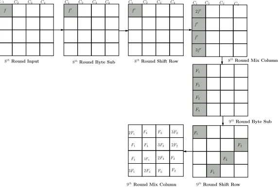
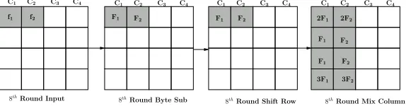
An attack that requires one ciphertext where a fault has been injected into the beginning of the eighth round of an instantiation of AES is described in [7]. This attack reduces the number of possible keys from 2128 to 232. A one byte fault injected into the beginning of the eighth round will propagate as shown in Figure 1. This corresponds to the modelM(1) defined above.
Let us considerCT,CT0
, andK10as defined in Section 2.1 where all elements are inF28. If we
use the interrelation between the faulty bytes of the first columnc1 at the end of the ninth round MixColumnas in Figure 1, we have following four equations:
2F =S−1(x
1⊕k1)⊕S−1(x01⊕k1)
F =S−1
(x14⊕k14)⊕S−1(x014⊕k14)
F =S−1(x
11⊕k11)⊕S
−1(x0
11⊕k11) 3F =S−1(x
8⊕k8)⊕S
−1(x0
8⊕k8)
,
whereF∈F28. These four equations can be solved for four key bytesk1,k8,k11andk14. The key
C3 C4
f f0
f0
2f0
f0
3f0
f0
F3
F4
F2
F3
F4
8thRound Input
8thRound Byte Sub 8thRound Mix Column
9thRound Byte Sub
F2
C2 C1 C2 C3 C4 C1 C2 C3 C1 C2 C3 C 4
C4
F1
8thRound Shift Row
9thRound Mix Column 9thRound Shift Row
F1 F4
2F4
F3
3F3
2F3
F3
3F2
F2
C1
F4 F1
2F1
2F2 3F4
F1
3F1
F2
Fig. 1.Propagation of byte fault induced at the input of eighth round
3.2 Extending to Multiple Rounds
If we consider the difference at the end of the eighth round, as defined in Section 3.1, a similar analysis can be conducted using Equations 1–4 defined below. We further definee1= 2f0,e2=f0,
e3=f0ande4= 3f0wheref0, ei∀i∈ {1, . . . ,4}are∈F28. The number of key hypotheses remaining
after evaluating these equations is expected to be 28 [12].
e1=S−1
(
14(
S−1(x1⊕k1)⊕((k1⊕S(k14⊕k10)⊕h10)))
⊕11(
S−1(x8⊕k8)⊕(k2⊕S(k15⊕k11))
)
⊕13(
S−1(x
11⊕k11)⊕(k3⊕S(k16⊕k12))
)
⊕ 9(
S−1(x8⊕k8)⊕(k4⊕S(k13⊕k9))
)
)
⊕S−1(
14(
S−1(x01⊕k1) ⊕((k1⊕S(k8⊕k10)⊕h10)))
⊕11(
S−1(x0
8⊕k8)⊕(k2⊕S(k15⊕k11)
)
⊕ 13(
S−1(x0
11⊕k11)⊕(k3⊕S(k16⊕k12))
)
⊕9(
S−1(x08⊕k8)⊕ (k4⊕S(k13⊕k9)))
)
(1)
e2=S−1
(
9(
S−1(x13⊕k13)⊕(k13⊕k9))
⊕14(
S−1(x10⊕k10)⊕(k10⊕k14)))
⊕11
(
S−1(x7⊕k7) ⊕(k15⊕k11)
)
⊕13(
S−1(x
4⊕k4)⊕(k16⊕k12)
)
)
⊕S−1
(
9(
S−1(x013⊕k13)⊕(k13⊕k9)
)
⊕14(
S−1(x010⊕k10)⊕(k10⊕k14)))
⊕ 11(
S−1(x07⊕k7) ⊕(k15⊕k11)
)
⊕13(
S−1(x0
4⊕k4)⊕(k16⊕k12)
)
)
(2)
e3=S
−1
(
13(
S−1(x9⊕k9)⊕(k9⊕k5)
)
⊕9(
S−1(x
6⊕k6)⊕(k10⊕k6))
)
⊕ 14(
S−1(x3⊕k3)⊕(k11⊕k7)
)
⊕11(
S−1(x
16⊕k16)⊕(k12⊕k8)
)
)
⊕S−1
(
13(
S−1(x09⊕k9)⊕(k9⊕k5)
)
⊕9(
S−1(x0
6⊕k6)⊕(k10⊕k6))
)
⊕ 14(
S−1(x03⊕k3) ⊕(k11⊕k7)
)
⊕11(
S−1(x016⊕k16)⊕(k12⊕k8))
)
e4=S
−1
(
11(
S−1(x2⊕k2)⊕(k2⊕k1)
)
⊕13(
S−1(x
5⊕k5)⊕(k6⊕k5))
)
⊕ 9(
S−1(x12⊕k12) ⊕(k10⊕k9)
)
⊕14(
S−1(x
15⊕k15)⊕(k14⊕k13)
)
)
⊕S−1
(
11(
S−1(x02⊕k2)⊕(k2⊕k1)
)
⊕13(
S−1(x05⊕k5)⊕(k6⊕k5)))
⊕ 9(
S−1(x012⊕k12) ⊕(k10⊕k9)
)
⊕14(
S−1(x0
15⊕k15)⊕(k14⊕k13)
)
)
(4)
4
Proposed Multi Byte Attack Based on Model
Md
In this section we perform an analysis similar to that described in the section where the faults injected correspond to the multiple byte fault model Md, where d is the number of diagonals
affected by a fault and 1≤d≤4. In this section we describe attacks based on previous work by Saha et al. where only the last round is analyzed [11], in a similar manner to that described in Section 3.2. For each model we extend the attack by Saha et al. by adding a second phase to the attack.
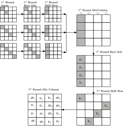
4.1 Multi Byte Attack Based on ModelM1(i)
In this section we consider model M1(i), where i bytes of one diagonal are affected by a fault injected at the beginning of the eighth round of an instantiation of AES. In all cases the first phase of the attack is as described in [11], since all the affected bytes are in the same column after the computation of theMixColumn at the end of the eighth round. This can be seen in Figure 2 that shows the propagation of fault; where a fault corrupts only one diagonal of the state matrix.
C1 C2 C3 C4
F4
F3
F2
F1
F1
F2
F3
F4
Input
8thRound
Byte Sub Shift Row
8thRound 8thRound
8thRound MixColumn
9thRound Byte Sub
9thRound Shift Row
F3
2F3
3F3
F3 3F2
2F2
F2
F2
2F1
F1
3F1
F1 3F4
F4
F4
2F4
9thRound Mix Column
Fig. 2.Propagation of one diagonal fault induced at the input of eighth round.
instances of model M1(i). For example, model M1(1) will correspond to the fault model required for the attack described in Section 3 and the number of key hypotheses can be reduced using the analysis described in Section 3.2. In the following sections we describe the second phase for the remaining modelsM1(i)for 2≤i≤4.
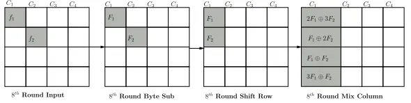
Proposed Second Phase of the Attack Based on Model M1(2). In this model an
attacker is expected to have injected a two bytes fault in any one of the four diagonals. Figure 3 shows the propagation of fault based on modelM1(2). Given that the number of key hypotheses has been reduced to 232 by the first phase of the attack.
C1 C2 C3 C4
F1⊕2F2
F1⊕F2
3F1⊕F2
8thRound Input
8thRound Byte Sub 8thRound Shift Row 8thRound Mix Column
F1
F2 F2
F1
f2
f1 2F1⊕3F2
C1 C2 C3 C4 C1 C2 C3 C4 C1 C2 C3 C4
Fig. 3.Propagation of two byte faults induced at the input of eighth round
If we denote the fault values of the first column at the end of eighth roundMixColumnoperation bye1, e2, e3, ande4 we get
e1= 2F1⊕3F2, e2=F1⊕2F2, e3=F1⊕F2, and e4= 3F1⊕F2
whereeifor ei ∈ {1, . . . ,4}is defined as described in Section 3.2. If we eliminate F1, F2 from the above system of equations we will have the following relationship betweene1, e2, e3ande4,
e2⊕e4=e1 and 2e2⊕3e4= 7e3 .
Here, it is clear that if we fix any two of the four variables{e1, e2, e3, e4}then the remaining two variables can only take one value. This gives 216 possible values for the quadruplet{e
1, e2, e3, e4} each of which will produce 0, 2 or 4 possible key hypotheses, but is expected to return one key hypotheses [9]. We can, therefore, state that an arbitrary key value will produce a valid quadruplet {e1, e2, e3, e4} with a probability of 216/232 = 2−16. This will, therefore, reduce the number of possible key hypotheses to 216.
Proposed Second Phase of the Attack Based on ModelM1(3). Similarly, if three bytes
in one diagonal are affect by a fault then we can define
e1= 2F1⊕3F2⊕F3, e2=F1⊕2F2⊕3F3,
e3=F1⊕F2⊕2F3, and e4= 3F1⊕F2⊕F3,
where we assume that the effect of the fault is as shown in Figure 4.
If we eliminate F1, F2 and F3 from the above system of equations we will have the following relationship betweene1, e2, e3 ande4,
11e1⊕13e2= 9e3⊕14e4 .
C1 C2 C3 C4 C1 C2 C3 C4 C1 C2 C3 C4
f1
8thRound Input
8thRound Byte Sub
8th
Round Shift Row 8th
Round Mix Column
F1
C2 C3 C4
C1
f2 F2
F3
F1⊕F2⊕2F3
F1⊕2F2⊕3F3
2F1⊕3F2⊕F3
3F1⊕F2⊕F3
F2
f3 F
3
F1
Fig. 4.Propagation of four byte faults induced at the input of eighth round
Proposed Multi Bytes Attack Based on ModeM1(4). If all four bytes in a diagonal are
affected then there is no information to be exploited in a second analysis phase. This is because there will be 232possible valid combinations for{e
1, e2, e3, e4}. The number of key hypotheses will not go below the 232 found using the attack defined by Saha et al. [11].
4.2 Proposed Multi Byte Attack Based one ModelM2(i,j)
In this section we apply our previous analysis on two diagonal fault modelM2(i,j); where the fault affects two of the four diagonal of the state matrix andiandjbytes are affected in these diagonals. As in Section 4.1, the attack is broken into two phases where the first phase has been defined previously by Saha et al. [11].
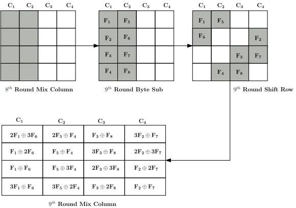
The First Phase of the Attack Based on ModelM2(i,j). In the first phase of the attack
the difference in the last round is produced by two columns of the state matrix at the end of the eighth round being corrupted by a fault. This analysis will be identical for all values ofiand
j assuming the same two diagonals are affected. If, for example, the two left-most columns are affected then the fault will propagate through the ninth round as shown in Figure 5.
C2 C3 C4
C1
C2 C3 C4
C1
C2 C3 C4
C1
C1 C3 C4
F1⊕F6
F1⊕2F6
2F1⊕3F6 2F5⊕F4
F5⊕3F4
3F5⊕2F4
3F3⊕F8
2F3⊕3F8
F3⊕2F8
F3⊕F8 3F2⊕F7
2F2⊕3F7
F2⊕2F7
F2⊕F7
F5⊕F4
3F1⊕F6
C2
F1
F6
F5
F8
F2
F4
F3 F7
8thRound Mix Column 9thRound Byte Sub 9thRound Shift Row
9thRound Mix Column
F1
F3
F4
F5
F7
F8
F6
F2
For each column can be analyzed independently. If we consider the first columnc1 and define the difference
a1= 2F1⊕3F6, a2=F1⊕2F6, a3=F1⊕F6, and a4= 3F1⊕F6,
as defined in Figure 5. If we eliminateF1, F6 from the above system of equations we will have a relation betweena1, a2, a3 anda4, we have
a2⊕a4=a1 and 2a2⊕3a4= 7a3
wherea1,a2,a3, anda4 can be expressed as,
a1 =S
−1(x
1⊕k1)⊕S
−1(x0
1⊕k1), a2=S
−1(x
14⊕k14)⊕S
−1(x0
14⊕k14),
a3=S−1(x11⊕k11)⊕S−1(x011⊕k11), and a4=S−1(x8⊕k8)⊕S−1(x08⊕k8) .
As described above this gives 216 possible values for the quadruplet{a
1, a2, a3, a4}each of which will produce 0, 2 or 4 possible key hypotheses, but is expected to return one key hypotheses [9]. This will, therefore, produce 216 hypotheses for the quadruplet{k1, k8, k11, k14}and, therefore, 264 key hypotheses for the secret key from analyzing all the four columns.
Proposed Second Phase of the Attack Based on Model M2(i,j). In this section we
present the proposed second phase of the attack on modelM2(i,j). There are 10 different instances of modelMi,j
2 based on the number of faulty bytes in two faulty diagonals. If we consider the two faulty diagonals asDxandDy and corresponding faulty columns ascxandcyat the end of eighth
roundMixColumnthen, depending on the values ofiandj, each of the two faulty columnscx and
cycan produce three different systems of equations in the manner described above. It is clear from
Section 4.1 that a faulty diagonal where all four bytes are affected does not help in reducing key hypotheses in the second phase.
Both sets of equations can be evaluated independently, and can both be used to reduce the number of valid key hypotheses. For example, if we considerM2(1,1), there two faulty diagonals in this model areD1 and D2 and the corresponding infected columns are c1 and c2. Figure 6 shows the propagation of a fault corresponding to modelM2(1,1).
C2
C1 C3 C4 C1 C2 C3 C4
F1
F1
3F1
2F1 2F2
F2
F2
3F2
C2
C1 C3 C4
C2
C1 C3 C4
f1 f2 F1 F2 F1 F2
8thRound Input 8thRound Byte Sub 8thRound Shift Row 8thRound Mix Column
Fig. 6.Propagation of faults based on model M2(1,1)
In the first stage of this attack the 264 key hypotheses generated from the first phase of the attack is tested by the system of equations generated for columnsc1 andc2. We note that the first stage of the attack will produce four sets of 216hypotheses each of which corresponds to 32 bits of the secret key. An attacker is not required to search through the entire 264hypotheses.
Each of the sets of equations will validate a given key hypothesis with a probability ofpi,j= 2−24,
and, therefore, the probability both sets of equations validate a given key hypothesis will be 2−48. The number of key hypotheses returned is 264·2−48= 216.
This method can be applied to all the instances of modelMi,j
Table 1.Results of The Proposed Second Phase of the Attack on ModelM2i,j.
Model Probability Key
(Mi,j
2 ) (pi,j) Hypotheses
M1,1
2 2
−48 216
M21,2 2−40 224
M21,3 2−32 232
M1,4
2 2
−24 240
M2,2
2 2
−32 232
Model Probability Key
(Mi,j
2 ) (pi,j) Hypotheses
M2,3
2 2
−24 240
M22,4 2−16 248
M23,3 2−16 248
M3,4
2 2
−8 256
M4,4
2 – 264
4.3 Proposed Attack Based on Model M3(i,j,k)
According to this model the induced fault affects three of the four diagonals of the state matrix. These three faulty diagonals havei, j, and k bytes modified respectively; where 1 ≤ i, j, k ≤ 4. As with the previous attacks, we divide this attack into two phases. Where, as previously, the first phase is defined by Saha et al. [11].
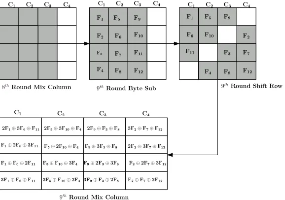
The First Phase of the Attack Based on ModelM3(i,j,k). This attack is similar to the
first phase of the attack based on modelM2(i,j). Figure 7 shows the propagation of such a fault.
F9
F10
F11
F12
F8
F7
F6
F5
F1
F2
F3
F4
F9
F5
F1
F2
F10
F11 F3 F7
F12
F8
F4
F6
C4
C3
C2
C1 C1 C2 C3 C4 C1 C2 C3 C4
8thRound Mix Column 9thRound Byte Sub
C1 C2 C3 C4
9thRound Mix Column F5⊕2F10⊕F4
2F9⊕F3⊕F8 3F2⊕F7⊕F12
F1⊕2F6⊕3F11
F5⊕F10⊕3F4
F9⊕3F3⊕F8
F9⊕2F3⊕3F8
3F9⊕F3⊕2F8
2F2⊕3F7⊕F12
F2⊕2F7⊕3F12
F2⊕F7⊕2F12
2F5⊕3F10⊕F4
3F1⊕F6⊕F11 3F5⊕F10⊕2F4
F1⊕F6⊕2F11
2F1⊕3F6⊕F11
9thRound Shift Row
Fig. 7.Propagation of faults based on modeM2(1,1)
The difference in the result of the ninth roundMixColumncan therefore be defined. For example, the left most columnc1 produces the quadruplet
a1= 2F1⊕3F6⊕F11, a2=F1⊕2F6⊕3F11,
If we eliminateF1,F6, andF11 from above equations we get,
11a1⊕13a2= 9a3⊕14a4
wherea1,a2,a3, anda4 can be expressed as,
a1=S−1(x1⊕k1)⊕S−1(x01⊕k1), a2=S−1(x14⊕k14)⊕S−1(x014⊕k14)
a3=S−1(x11⊕k11)⊕S−1(x011⊕k11), and a4=S−1(x8⊕k8)⊕S−1(x08⊕k8)
The above equations will produce 224possible values for the quadruplet{k1, k8, k11, k14}. Similarly, solving the equivalent equations for the other columns will each return 224 hypotheses, producing 296 key hypotheses for the first phase of the attack.
Proposed Second Phase of the Attack Based on ModelM3i,j,k The modelM3i,j,khas
three faulty diagonals and three corresponding faulty columns at the end of eighth roundMixColumn. Let us assume that the faulty diagonals areDx, Dy, Dz and the corresponding faulty columns are
cx, cy, cz. Each of these three columns will produce a system of equations similar to the second
phase of the attack in Section 4.2. Therefore the key reduction process is affected by the equations formed to represent the difference produced by the affected columns cx, cy and cz, in the same
manner as previously described in Section 4.2. There are 20 possible instances of modelMi,j,k
3 , and their effect on reducing the 296possible key hypotheses produced by the first phase of the attack is summarized in Table 2.
Table 2.Results of the proposed second phase of the attack on ModelM3i,j,k.
Model Probability Key
(Mi,j,k
3 ) (pi,j,k) Hypotheses
M1,1,1
3 2
−72 224
M31,1,2 2
−64 232
M31,1,3 2−56 240
M1,1,4
3 2
−48 248
M1,2,2
3 2
−56 240
M31,2,3 2
−48 248
M31,2,4 2−40 256
M1,3,3
3 2
−40 256
M1,3,4
3 2
−32 264
M31,4,4 2
−24 272
Model Probability Key
(Mi,j,k
3 ) (pi,j,k) Hypotheses
M2,2,2
3 2
−48 248
M32,2,3 2
−40 256
M32,2,4 2−32 264
M2,3,3
3 2
−32 264
M2,3,4
3 2
−24 272
M32,4,4 2
−16 280
M33,3,3 2−24 272
M3,3,4
3 2
−16 280
M3,4,4
3 2
−8 288
M34,4,4 −− 296
5
Experimental Result
one clock having a higher frequency than the other. The clocks are multiplexed in such a way that when the eighth round of the AES starts the device switches to a faster clock before returning to a normal clock speed. We used ChipScope Pro 7.1 analyzer to observe the faulty bytes in the state matrix of AES hardware running on the FPGA. The experiment started with a fast clock frequency set to 72 MHz. This frequency was gradually increased at the rate 0.2 MHz per step. At each step we perform 512 attempts to inject faults.
Appendix A summarizes the experimental results. The first column represents the fast clock frequency with which we attempted to inject faults. The second column gives the number of fault free samples out of 512 attempts and the subsequent columns depicts the number of faulty samples as per the corresponding fault model. The columnsM1, M2, M3, M4represent the number of faulty sample corresponding to faults affecting one, two, three, and four diagonals respectively. The rest of the columns correspond to the number of faulty samples of the 6 instances of fault models
M1(i), M2(i,j), andM3(i,j,k). Only those models for which we acquired at least one faulty sample were included in Appendix A.
The first fault appeared when the glitch clock frequency was set to 72.6 MHz, although only faults corresponding to modelM1(1) were observed with a clock speed less than 73.8 MHz. The experiment was continued with up to 80 MHz of clock frequency and we can observe that the probability of acquiring a sample belonging to a particular fault model is not uniform. Furthermore, it may be noted that the experimental findings show that the induced faults indeed belong to the desirable models (for which the proposed attacks reduce the key space to sizes which can be easily brute force searched). For example, the worst observed model is M3(1,1,3), in case of which the proposed attack reduces the key space to 240. In most cases, however the faults belong to the faults
M1(1), M2(1,1) andM2(1,2) for which the attacks reduce the key space to expected values of 28,216 and 224 respectively. Repeated experiments show that the nature and distribution of faults can be reproduced, thus showing that the attacker can suitably control the most probable faults to belong to models for which the attacks reduce the key space to practical limits. As the ratios of faults corresponding to a particular model and clock frequency can be reproduced, following the results tabulated in Appendix A an attacker can monitor the clock frequency and produce faults corresponding to a desired model with high probability.
6
Conclusion
The paper presents an differential fault analysis of AES where multiple bytes can be affected by a fault and an attacker will only require one acquisition to recover the secret key used. Experimental results have been provided to show that the practicality of the attack is improved by the techniques proposed in the paper for faults that affect multiple bytes. Not all of the attacks are practical as described since the number of key hypotheses generated is too large for a practical exhaustive search. However, the number of key hypotheses can be further reduced by acquiring more faulty ciphertexts that correspond to the same fault model. An attacker can then take the intersection of the key hypotheses generated by the first and second phase independently.
References
1. H. Bar-El, H. Choukri, D. Naccache, M. Tunstall, and C. Whelan. The sorcerer’s apprentice guide to fault attacks. Proceedings of the IEEE, 94(2):370–382, 2006.
2. E. Biham and A. Shamir. Differential fault analysis of secret key cryptosystems. In B. S. Kaliski, editor,Advances in Cryptology — CRYPTO ’97, volume 1294 of LNCS, pages 513– 525. Springer, 1997.
3. J. Bl¨omer and J.-P. Seifert. Fault based cryptanalysis of the advanced encryption standard (AES). In R. N. Wright, editor,Financial Cryptography — FC 2003, volume 2742 ofLNCS, pages 162–181. Springer, 2003.
4. D. Boneh, R. DeMillo, and R. Lipton. On the importance of checking cryptographic protocols for faults. In W. Fumy, editor,Advances in Cryptology — EUROCRYPT ’97, volume 1233 of
5. P. Dusart, G. Letourneux, and O. Vivolo. Differential fault analysis on A.E.S. In J. Zhou, M. Yung, and Y. Han, editors,Applied Cryptography and Network Security — ACNS 2003, volume 2846 ofLNCS, pages 293–306. Springer, 2003.
6. C. Giraud. DFA on AES. In H. Dobbertin, V. Rijmen, and A. Sowa, editors, International
Conference Advanced Encryption Standard — AES 2004, volume 3373 ofLNCS, pages 27–41.
Springer, 2004.
7. D. Mukhopadhyay. An improved fault based attack of the advanced encryption standard. In B. Preneel, editor, Progress in Cryptology — AFRICACRYPT 2009, volume 5580 of LNCS, pages 421–434. Springer, 2009.
8. National Institute of Standards and Technology (NIST). Advanced Encryption Standard (AES). FIPS Publication 197, available for download athttp://www.itl.nist.gov/fipspubs/, 2001. 9. K. Nyberg. Differentially uniform mappings for cryptography. In T. Helleseth, editor,Advances
in Cryptology — EUROCRYPT ’93, volume 765 ofLNCS, pages 55–64. Springer, 1993.
10. G. Piret and J.-J. Quisquater. A differential fault attack technique against SPN structure, with application to the AES and KHAZAD. In C. D. Walter, C¸ . K. Ko¸c, and C. Paar, editors,
Cryptographic Hardware and Embedded Systems — CHES 2003, volume 2779 ofLNCS, pages
77–88. Springer, 2003.
11. D. Saha, D. Mukhopadhyay, and D. RoyChowdhury. A diagonal fault attack on the Advanced Encryption Standard. Cryptology ePrint Archive, Report 2009/581, 2009. http://eprint. iacr.org/.
12. M. Tunstall and D. Mukhopadhyay. Differential fault analysis of the advanced encryption standard using a single fault. Cryptology ePrint Archive, Report 2009/575, 2009. http:// eprint.iacr.org/.
A
Experimental Results
Clock FaultM1 M2 M3 M4 M1(1)M (1,1)
2 M
(1,2)
2 M
(1,3)
2 M
(1,1,2)
3 M
(1,1,3) 3 Frequency(MHz) free
72.0 512 0 0 0 0 0 0 0 0 0 0
72.2 512 0 0 0 0 0 0 0 0 0 0
72.4 512 0 0 0 0 0 0 0 0 0 0
72.6 510 2 0 0 0 2 0 0 0 0 0
72.8 511 1 0 0 0 1 0 0 0 0 0
73.0 508 4 0 0 0 4 0 0 0 0 0
73.2 504 8 0 0 0 8 0 0 0 0 0
73.4 507 5 0 0 0 5 0 0 0 0 0
73.6 490 22 0 0 0 22 0 0 0 0 0
73.8 489 23 0 0 0 23 0 0 0 0 0
74.0 419 79 14 0 0 79 14 0 0 0 0
74.2 448 60 4 0 0 60 4 0 0 0 0
74.4 437 64 14 0 0 64 13 1 0 0 0
74.6 403 94 15 0 0 94 15 0 0 0 0
74.8 408 99 5 0 0 99 5 0 0 0 0
77.0 0 20 429 47 16 20 68 361 0 23 24 77.2 0 0 336 123 53 0 16 320 0 32 91 77.4 0 2 313 101 96 2 21 292 0 31 70 77.6 0 1 298 123 90 1 9 288 1 46 77 77.8 0 12 409 71 20 12 42 367 0 42 29 78.0 15 59 415 22 1 59 107 308 0 19 3 78.2 0 2 210 160 140 2 12 198 0 62 98 78.4 0 5 365 94 48 5 26 339 0 36 58 78.6 0 4 296 126 86 4 11 285 0 50 76 78.8 0 0 133 110 269 0 0 133 0 27 83 79.0 0 0 144 112 256 0 6 138 0 20 92 79.2 0 0 150 114 248 0 0 150 0 28 86
79.4 0 0 21 20 471 0 0 21 0 4 16
79.6 0 0 18 24 470 0 0 18 0 3 21
79.8 0 0 14 21 477 0 0 14 0 2 19