c
Owned by the authors, published by EDP Sciences, 2015
Evaluation of a strain based failure criterion for the multi-constituent
composite model under shock loading
Christopher T. Key1,a, Shane C. Schumacher2, and C. Scott Alexander2
1HI-TEST Laboratories Inc., Applied Technologies Group, 32 Murphys Drive, Groton, CT 06340, USA 2Sandia National Laboratories, PO Box 5800, Albuquerque, NM 87185, USA
Abstract. This study details and demonstrates a strain-based criterion for the prediction of polymer matrix composite material damage and failure under shock loading conditions. Shock loading conditions are characterized by high-speed impacts or explosive events that result in very high pressures in the materials involved. These material pressures can reach hundreds of kbar and often exceed the material strengths by several orders of magnitude. Researchers have shown that under these high pressures, composites exhibit significant increases in stiffness and strength. In this work we summarize modifications to a previous stress based interactive failure criterion based on the model initially proposed by Hashin, to include strain dependence. The failure criterion is combined with the multi-constituent composite constitutive model (MCM) within a shock physics hydrocode. The constitutive model allows for decomposition of the composite stress and strain fields into the individual phase averaged constituent level stress and strain fields, which are then applied to the failure criterion. Numerical simulations of a metallic sphere impacting carbon/epoxy composite plates at velocities up to 1000 m/s are performed using both the stress and strain based criterion. These simulation results are compared to experimental tests to illustrate the advantages of a strain-based criterion in the shock environment.
1. Introduction
Composite materials are often used in shock loading applications caused by high-velocity impacts, where the strain rates can reach on the order of 107 and the pressures are often in the hundreds of kbar. Hydrocodes are commonly used to simulate material response under such conditions. Hydrocodes typically separate a material’s response into volumetric and deviatoric components as given in Eq. (1). The deviatoric (si j) or distortional response of the material is modeled with a constitutive model, while the volumetric (P) response is modeled using an equation of state (EOS).
σi j =si j +Pδi j. (1) The work presented in this paper utilizes the shock physics hydrocode CTH [1] to model unidirectional composite materials under high velocity impacts where the pressures can reach very high levels. As a result of these high pressures, the pressure term on the right hand side of Eq. (1) can dominate the material’s stress response. As a consequence, damage and failure predictions using traditional stress based failure criterion can often times be misleading. Factors which influence these misleading results include; stiffness and strength increases at elevated pressures [2], the retention of shearing resistance under compression and the fact that these materials often times cannot react on the time scales of the pressure wave propagations.
Figure1shows an example of the pressure dependent strength behavior for a graphite/epoxy composite material. aCorresponding author:[email protected]
This data shows a nearly 2 times increase in the matrix dominated failure modes of the material as a result of the applied pressure being increased from standard atmospheric conditions to 6 kbar. Figure 1 also shows that fiber dominated failure modes are less influenced by the effect of pressure than are matrix modes. These observations lead to the suggestion that a deformation or strain-based criterion may be more suitable for shock loading problems.
In what follows, we briefly outline the composite material constitutive model and the equation of state model used for these initial studies. We then detail both the stress and strain-based failure criterion used along with the experimental test details used to support that analytical work. Finally, we compare the results of the two failure criterion against the experimental test results of a carbon-epoxy panel subjected to spherical projectile impacts.
2. Composite material models
2.1. Constitutive model
To simulate the anisotropic response of a unidirectional composite material, the multi-constituent Composite Model (MCM) within the CTH constitutive material library was utilized. The MCM model is based on the work of Hill [3] and adaptation of Garnich and Hansen [4], where a detailed derivation of the approach and corresponding decomposition relationships can be found.
This MCM model is based upon a multicontinuum concept, which provides constituent (fiber and matrix) averaged stress and strain fields at the continuum level. To do this, the MCM model assumes that at each point
Figure 1.Pressure dependent strength data for fiber and matrix fracture modes in composite materials [2].
within a structure, there exists a representative volume element (RVE). For the unidirectional composite material considered in this work, Fig.2illustrates the hexagonally packed basic repeating unit microstructure used, where the red regions represent the carbon fibers and the blue regions are the epoxy matrix.
The volume averaged stress fields for each of the constituents, which comprise the RVE, can be expressed as:
¯ σi=
1 Vi
Di ¯
σ(X)d V. (2) For the case of a unidirectional composite as shown in Fig.2, i=2, representing the fiber and matrix constituent. Volume averaging leads to the relationship in Eq. (3) between the homogenized composite and constituent stress fields.
¯
σ =φmatr i xσ¯matr i x +φf i berσ¯f i ber. (3) Where in this equationφmatr i x andφf i ber are the volume fractions of the matrix and fiber, respectively.
Combining Eqs. (2) and (3) with the linear elastic constitutive relationships for the composite and con-stituents, the following strain decomposition equation can be derived.
{εmatr i x}=
φmatr i x[I]+φf i ber[A] −1{
ε} (4) where,
[A]=−φmatr i x φf i ber
[C]−Cf i ber
([C]−[Cmatr i x]). (5)
Equation (4) provides the volume averaged continuum strain field in the matrix constituent as a function of the composite strain field (ε) and the fiber (Cf i ber), matrix (Cmatr i x) and composite (C) stiffness matrices. Next, using the matrix averaged strain field, the fiber averaged strain
Figure 2. Hexagonally packed unidirectional composite microstructure.
field can be found by applying a similar volume averaging scheme as used in Eq. (3) to yield:
f i ber
= φ1
f i ber
({ε} −φmatr i x{εmatr i x}). (6)
Finally, the average stress fields for the fiber and matrix can be calculated using their respective linear elastic constitutive relationship.
2.2. Equation of state coupling
One implication of the anisotropy of the unidirectional composite material considered in this work, is the inherent coupling between the deviatoric and volumetric responses of the material. This coupling causes a problem in a hydrocode, where the deviatoric and volumetric responses are separated. Therefore, the MCM model must account for the fact that hydrostatic pressure applied to a finite volume causes not only a volume change, but also a shape or distortional change.
The coupling is accounted for within the MCM model using the relationships developed by Lukyanov [5]. Lukyanov’s relationships modify the pressure term, which results from the EOS, such that an applied pressure only causes a volume change without a distortional change. This approach therefore retains the traditional definition of pressure.
Lukyanov expressed the pressure in term of a tensor rather than the traditional scalar according to Eq. (7).
˜
P =−P∗αi j. (7) WhereP∗is the scalar pressure defined as:
P∗=PE O S+ βi jsi j αi jβi j
· (8)
Finally, combining the relationship of Eq. (8) with the stress decomposition relationship of Eq. (1), Lukyanov arrives at the following relationship for the deviatoric stress:
si j =σi j −αi j· 1
||α||σklαkl. (9) Equation (9) accounts for the coupling effects of the pressure on the deviatoric stresses just as Eq. (8) accounted for the coupling effects of the deviatoric stresses on the pressure.
The reader is referenced to Schumacher and Key [7] for a detailed description of the anisotropic equation of state coupling model and its implementation within CTH. 2.3. Failure criteria
The failure criteria used within the MCM model for this work is based on the unidirectional composite material failure criterion of Hashin [8]. Hashin’s criterion predicted constituent level failure modes based on the stress fields of the homogenized composite. Mayes and Hansen [9] modified Hashin’s criterion such that the fiber and matrix failure modes were predicted as a function of their individual volume averaged continuum stress fields, which are a direct result of the MCM model. Here we provide a brief review of the constituent level failure criteria of Mayes and Hansen. Further details of the development of these criterions can be found in Mayes [10] and Mayes and Hansen [9].
2.3.1. Stress-based failure criterion
The MCM criteria is based on the assumption that unidirectional fiber reinforced composite materials are transversely isotropic. Therefore, the criteria can be expressed in terms of transversely isotropic stress invariants [11] given in Eq. (10).
I1=σ11,
I2=σ22 +σ33,
I3=σ2
22+σ332 +2σ232, (10) I4=σ122 +σ132,
I5=σ22σ122 +σ33σ132 +2σ12σ13σ23.
Using the quadratic terms from Hashin’s original criterion, the transversely isotropic stress invariants from Eq. (10) and simplifications detailed by Mayes and Hansen, the following general form of the MCM failure criterion is arrived at:
A1I12+A2I22+A3I3+A4I4=1. (11) Where the A terms are strength coefficients which are functions of the tensile, compressive and shear strength of the material.
Equation (11) can be simplified to predict matrix failure using the observation that conventional composite materials are composed of fibers which have significantly higher strengths than the matrix which bonds them
together. Therefore, transverse failure of a unidirectional composite material is controlled by the strength of the matrix. If one assumes that the fibers of a unidirectional fiber reinforced composite run in the 1-direction, the A1 coefficient in Eq. (11) can be set to zero, as it is only a function of the longitudinal stress (σ11) and the resulting matrix failure criterion used in the MCM model is then:
±Am 2
I2m2+Am3I3m+ Am4I4m=1. (12) The matrix strength coefficients in Eq. (12) are determined through application of in-plane shear, transverse shear, transverse tension and transverse compression uniaxial load cases resulting in the matrix failure strength coefficients give in Eq. (13).
±Am 2 =
1 ±
S22m
22 +±S2233m 2∗
1−
±
S2222m2+±S3322m2
2Sm 23
2
Am3 = 1 2S23m2 Am4 = 1
Sm 12
2· (13)
In Eqs. (12) and (13) the±symbol indicates a dependence on the parameters for tensile vs. compressive stress.
Similar to the matrix failure criterion approach, one can assume that the higher strength of the fibers means the longitudinal failure of the composite material is controlled by the strength of the fibers. Hence, the A2and A3terms in Eq. (11) are set equal to zero as they are related to the transverse stresses (σ22andσ33). The resulting fiber failure criterion used in the MCM model is then:
±Af 1
I1f
2
+A4fI4f =1. (14)
The coefficients for the fiber failure criterion of Eq. (13) are determined by applied uniaxial loading conditions of in-plane shear, longitudinal compression and longitudinal tension, resulting in the fiber failure strength coefficients given in Eq. (15).
±Af 1 =
1
±Sf 11
2
A4f = 1 S12f
2· (15)
2.3.2. Strain-based failure criterion
3. Experimental testing details
The high velocity impact experiments for this work were performed at Sandia National Laboratories using single and two stage light gas guns. The gas guns were used to fire1/4inch diameter steel spheres at velocities from 250 to 1000 m/s. The test setup included flash x-ray or high-speed cameras to capture the penetration event, panel motion and projectile residual velocity if applicable. Following each impact test, the composite panel was inspected using ultrasound to measure the extent of damage that occurred during the impact event.
The composite material system used to fabricate the panel was IM7 carbon fibers pre-impregnated with a toughened epoxy (8552) from Hexcel. Each composite target panel was fabricated to be 7.5 inches by 7.5 inches square with a fiber volume fraction of 68% and thicknesses ranging from 1/4 to 1 inch. The lamination schedule of each panel was quasi-isotropic [0/90/+45/−45/−45/+45/90/0]a, with the repetitions of this base layup (a) being repeated as necessary to achieve the overall desired panel thickness.
In this paper we focus only on two of the tests conducted which demonstrate the extremes of the composite damage. These two tests, impacting 1/2 inch thick panels, include an impact velocity of 506 m/s where the projectile did not penetrate the composite target panel and a 1073 m/s impact where the projectile perforated the composite panel.
4. Numerical model details
The CTH numerical simulations used to evaluate the failure criteria where performed using a full 3-dimensional model of both the composite target panel and spherical projectile. The projectile was modeled using a simple rate-dependent plasticity constitutive model and a Mie-Gr¨uneisen EOS with an initial density of 8.13 g/cm3 to represent high-density steel.
The composite target panel was modeled using the previously described MCM composite model with a quasi-isotropic layup and an initial density of 1.56 g/cm3. The stiffness parameters for the fiber and matrix constituents were taken from Key et al. [12], while the composite stiffness properties were generated using the constituent properties and the finite element micromechanics model shown previously in Fig. 2. The initial constituent material strength properties were also determined from the micromechanics model and the composite material strength properties of Key et al. [12].
As a simple attempt to account for the strength increases that occur due to the elevated pressures and strains rates, a strength increase factor estimate of 1.75 was applied to each of the ultimate stress and strain properties. This factor was estimated from the data of Shin et al. of Fig.1, where although the peak pressures in our problem are at or above 100 kbar, there was no experimental data found to support further strengthening above the 6 kbar pressure of Shin.
Finally, each of the two impact velocity conditions was modeled using various different Eularian mesh densities as part of a larger effort. For this paper we will use the
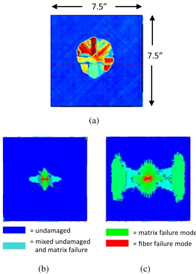
(a)
(b) (c)
Figure 3.Damage patterns in (a) ultrasound data, (b) strain-based and, (c) stress-based predictions (Mesh 1) for 506 m/s impact.
following naming convention when referring to each of the different densities:
Mesh 1: 0.273 cm×0.273 cm×0.1524 cm Mesh 2: 0.136 cm×0.136 cm×0.0762 cm Mesh 3: 0.0683 cm×0.0653 cm×0.0635 cm Mesh 4: 0.0453 cm×0.453 cm×0.0423 cm.
As part of a larger effort, the different mesh densities were chosen to study their effect on both the predicted damage patterns and the residual velocity predictions. However, the main focus of this paper is on the differences in the numerical predictions as related to the stress and strain-based failure criterion. Therefore, the mesh density differences are only provided in select results.
5. Results
In order to evaluate the performance of the MCM model using both the stress and strain-based failure criteria, two evaluation metrics were chosen. First, the damage patterns predicted by the analytical simulations were compared to the observed ultrasonic post-test patterns. Second, the measured projectile residual velocity from the experimental test was compared directly against the analytically predicted residual velocity.
Table 1.Residual velocity comparisons for 506 m/s impact.
Mesh 1 Mesh 2 Mesh 3
Experimental 0 m/s
Strain-based criterion 0 m/s 0 m/s 0 m/s
Stress-based criterion 0 m/s 20 m/s 100 m/s
5.1. 1/2inch panel; 506 m/s impact velocity
Figure 3(a) shows the damage patterns measured from the ultrasonic inspection of the 1/2 inch panel after the spherical projectile impacted the composite target panel at 506 m/s. From this image one can see that the damage envelope through the thickness of the target panel is nearly circular in shape and consists of striations, which align with the quasi-isotropic lamination schedule (0◦, 90◦, +45◦ and−45◦) of the panel. The damage extent is also evident in this figure, as the entire 7.5 inch by 7.5 inch domain of the panel is shown.
Figure 3(b) shows the predicted damage envelope from the CTH-MCM simulation when using the strain-based failure criterion over the entire 7.5 inch by 7.5 inch panel domain. The damage envelope in this figure and all subsequent numerical images was generated by superimposing 2D damage slices of the laminate at the center of each ply. This approach was necessary as there is currently no capability available within the CTH post-processing package to generate the through thickness envelopes.
From Fig. 3(b) one can see that the strain-based criterion captures the basic characteristics of the damage envelope that are seen in the ultrasound results. Specifically, the predicted striations and extent of the damage in the 0◦ direction (horizontal) is very similar to the extent in the ultrasound. The predicted damage extents or striation in the 90◦,+45◦and−45◦ directions is also evident. However, the extent of these directions appears to be approximately1/2 the extent seen in the experimental data for the 90◦,+45◦and−45◦orientations.
Figure 3(c) shows the predicted results of the same simulation using the stress-based criterion. From this figure it is evident that the stress-based criterion significantly over-predicts the damage extent in the composite panel in the 0◦ direction (horizontal) as compared to the ultrasound results. In this direction the damage is observed to extend nearly to the plate free-edge, with large regions of damage far from the central impact zone. Also, there is very little evidence of the directional striations seen in the experimental results and the strain-based results.
For this experimental configuration, the projectile was defeated by the composite panel such that the residual velocity of the projectile was 0 m/s. The residual velocities for the spherical projectile predicted by the CTH-MCM simulations are given in Table 1 for each of the failure criteria. The results in Table1show that the strain-based criterion predicts that the composite panel will defeat the spherical projectile, as was observed in the experimental testing, for each of the mesh densities. However, for the stress-based criterion, it is evident that as the mesh density increases, the model predicts that the projectile defeats the
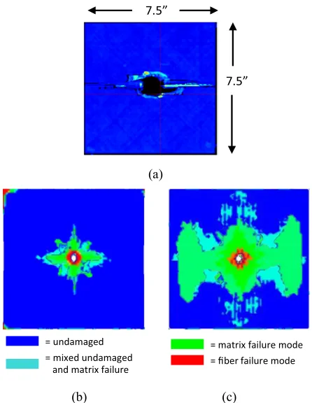
(a)
(b) (c)
Figure 4.Damage patterns in (a) ultrasound data, (b) strain-based and, (c) stress-based predictions (Mesh 1) for 1076 m/s impact.
composite panel and the residual velocity of the penetrator is approximately 100 m/s for the highest mesh density.
Table 2.Residual velocity comparisons for 1076 m/s impact.
Mesh 1 Mesh 2 Mesh 3 Mesh 4
Experimental 562 m/s
Strain-based 25 m/s 300 m/s 525 m/s 560 m/s
criterion
Stress-based 150 m/s 325 m/s 450 m/s 500 m/s
criterion
5.2. 1/2inch panel; 1076 m/s impact velocity
Figure4(a) shows the post-test ultrasound evaluation of the 1/2inch panel after being impacted at 1076 m/s. Unlike the slower velocity condition discussed in the previous section, under this increased velocity the projectile easily defeats the panel. As a result of the projectile penetrating the panel, the ultrasound image of Fig.4(a) can be misleading. First, looking at the figure one might interpret the black regions as holes or perforations in the panel; however, this is not the case. The black regions in the ultrasound are regions on the panel where the ultrasound was unable to make a conclusive measurement due to the large and varying amounts of interference present in the ultrasound signal. Visual examination of the panel confirms that the perforation in the panel was almost exactly the same diameter as the spherical projectile (1/4inch).
(Fig. 4(b)) shows damage extents and patterns that are similar to those observed in the tested panel. The stress-based criterion results shown in Fig. 4(c) were again much greater in extent than what was observed in the experimental results. These prediction results were similar to the previous condition in that they extended nearly to the free-edges of the panel in the 0◦and 90◦directions.
Table2shows the residual velocity prediction for this impact velocity along with the experimentally measured residual velocity. These results show that both criterions are converging towards the experimental results. However, the strain-based criterion appears to be converging on the experimental result quicker than the stress-based criterion. Tables 2 and 3 together also show that at the less dense mesh configurations (Mesh 1, 2) a similar trend is observed where the stress-based failure criterion predicts a higher residual velocity. However, between Mesh 2 and Mesh 3, the trend reverses for the high velocity shot and the residual velocity for the strain-based criterion is higher than the stress-based residual velocity. Efforts are currently ongoing to better understand the mesh dependent behaviors seen in for each of these criterion results.
6. Conclusions
The preliminary results of this work show that a stress-based failure criterion tends to over predict the damage extent of the composite panels when subjected to shock loading. The results also show that this increased damage leads to an over-prediction of the projectile residual velocity. In contrast, the strain-based criterion appears to capture the basic characteristics of the damage patterns observed in the experimental testing and also does a good job of converging on the projectile residual velocity.
These results lead to the conclusion that when modeling composite materials under high velocity impact conditions, a strain based failure criterion may be more appropriate than a stress-based, pressure independent criterion. Future work will include the evaluation of a pressure-dependent, stress or strain-based criteria [13] to eliminate the artificial strengthening parameter applied during these early studies.
References
[1] J.M. McGlaun, S.L. Thompson, L.N. Kmetyk, M.G. Elrick, Int. J. Impact Eng.10, 351 (1990)
[2] E.S. Shin, K.D. Pae, J. Compos. Mater. 26, 828 (1992)
[3] R. Hill, J. Mechan. Phys. Solids12, 199–212 (1964) [4] M.R. Garnich, A.C. Hansen, J. Compos. Mater.31,
71 (1997)
[5] A.A. Lukyanov, Int. J. Plasticity24, 140 (2008) [6] E.S. Hertel, G.I. Kerley,Sandia National
Laborato-ries ReportSAND98-0947 (1998)
[7] S.C. Schumacher, C.T. Key, Sandia National Laboratories ReportSAND2012-7714 (2012) [8] Z. Hashin, J. Appl. Mech.47, 329 (1980)
[9] J.S. Mayes, A.C. Hansen, Comp. Sci. Tech.64, 379 (2004)
[10] J.S. Mayes,University of Wyoming Doctoral Disser-tation(1999)
[11] A.C. Hansen, D.M. Blackketter, D.E. Walrath, J. Appl. Mech.58, 881 (1991)
[12] C.T. Key, M.R. Garnich, A.C. Hansen, Compos. Struct.65, 357 (2004)
![Figure 1. Pressure dependent strength data for fiber and matrixfracture modes in composite materials [2].](https://thumb-us.123doks.com/thumbv2/123dok_us/8176543.1365572/2.595.67.273.69.298/figure-pressure-dependent-strength-ber-matrixfracture-composite-materials.webp)