1
Preparation of Porous Silicon Nitride Ceramics by Microwave
Sintering and Its Performance Evaluation
Chun-fang XIAO1Bing HAN2
(1. changsha aeronautical vocational and technical college, changsha 410124
2. Liaoning university of science and technology institute of mechanical engineering and automation,Anshan 114051 [email protected] )
Supported by Natural Science Foundation of Hunan Province. Item number:2017JJ5056.
Abstract
In this paper, the preparationmethods of porous silicon nitride materials with controllable dielectric constant and pore structure were systematically studied. By using microwave sintering technology, porous silicon nitride materials with high closed pore ratio were prepared by adjusting the content of sintering additives and sintering process parameters, and controlling the grain boundary phase and pore structure and size. The effects of sintering conditions on the total porosity, closed porosity, pore structure and dielectric properties of materials were systematically studied.
Key word
Porous silicon nitride ceramics;Microwave sintering technology ;
agglomeration process;Law of influence.
Introduction
Silicon nitride ceramics have excellent mechanical properties, good thermal and chemical stability, low dielectric constant and dielectric loss. It is an ideal choice for electromagnetic wave transmission materials of high-speed aircraft. Porous silicon nitride ceramics have excellent properties of high strength, high temperature resistance and porous lightweight. Its dielectric constant can be adjusted in the range of 2-8. It has
outstanding advantages in high Mach number, wide band and low aiming error radome materials. It has become one of the research hotspots of high temperature transmissive materials in recent decades. Low dielectric
porous silicon nitride ceramics were prepared by microwave sintering.
Porous silicon nitride materials with high closed pore ratio were fabricated by microwave sintering technology by adjusting sintering additive content, controlling pore size and grain boundary phase. The green body was pre-nitrided by pressure sintering process in atmosphere to form RE10N2(SiO4)6
or RE4Si2N2O7 grain boundary phase on the
surface of the material particles, and then microwave sintering was used to make the silicon nitride particles form hollow structure. The effects of sintering conditions on the total porosity, closed porosity, pore structure and dielectric properties of materials were systematically studied.[1]-[3]
Porosity control of porous silicon
nitride ceramics
In this paper, the primary and secondary nitriding treatments of silicon powder after ball milling are selected. Fig. 1 shows the effect of the content of sintering aids oxidizing shirt on the porosity of porous Si3N4 at
different temperatures. According to the principle of system optimization, the primary nitriding temperature chosen in this
experiment is 1200 ℃. Three secondary nitriding temperatures were tested at 1200℃, 1280℃ and 1350℃ respectively. It is shown from the figure that the material can achieve the highest porosity when the content of Sm2O3 is 0.8mol.% at 1350℃.
2
Fig.1 Effect of content of Samarium oxide on the porosity in the different
nitrided number and
nitrided temperature (a) one time nitriding (b)two nitriding
I
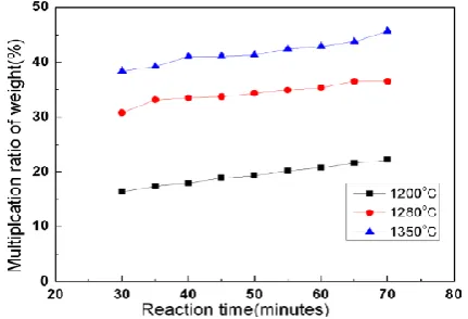
n order to determine the final nitriding holding time of microwave sintering, the nitriding rate of samples with the same ratio was compared in microwave sintering furnace. After calculation, the theoretical nitriding rate of silicon powder was 66%. Fig. 2 is the experimental results for each additional 5 minutes after holding in microwave oven for half an hour. It can be
seen from the figure that with the prolongation of holding time, the nitriding weight gain rate increases gradually, and the final nitriding weight gain rate is the highest at 1350。
C, which is close to the theoretical weight gain rate. Therefore, in this study, microwave sintering secondary nitriding was adopted to prolong the holding time at 1350。
C.[4]-[6]
Fig. 2 The relationship betwween nitrided time and increase
T
he different nitriding holding time of silicon powder at 1350。
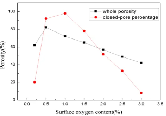
C corresponds to the different oxygen content on the surface of silicon powder. Fig. 3 shows the effect of oxygen content on the porosity and the closed pore ratio of the material. When the oxygen content on the surface of the silicon powder is 0.5%, the total pore ratio of the material reaches the highest value, and the closed pore ratio is
3
Fig.3 Effect of oxygens content in the silicon surface on whole porosity and closed-pore percentage
Figure 4 (a) shows the effect of sintering additive content on the flexural strength, porosity and closed porosity of porous Si3N4.
It can be seen from the figure that with the increase of sintering additive content, the flexural strength and porosity of the material increase first and then decrease. In the process of reaction sintering, RE-Si-N-O compound is formed by the reaction between sintering additives and SiO2 on the surface of silicon
powder. This compound forms a shell on the surface of silicon powder, which is coated on the outside of silicon powder. The silicon powder inside is diffused by microwave sintering, and the whole material becomes a hollow structure with closed pore. If the amount of sintering additives is small, the RE-Si-N-O compound formed is too small to
4
Fig. 4 Effect of sintering additives content on the porosity and bending strength (a)porosity and bending strength; (b) close porosity
Phase Analysis of Porous Silicon
Nitride Ceramics
Fig. 5 is an XRD diagram of porous silicon nitride sintered at 1350。
C. It can be
seen from the diagram that silicon powder has been completely nitrided to form α phase silicon nitride.
Fig. 5 XRD of Si3N4 pore ceramics after microwave sintering at 1350。C
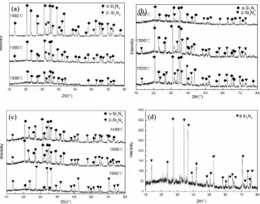
In order to obtain β silicon nitride with excellent properties, porous silicon nitride sintered by microwave was re-sintered. Fig. 6 is the XRD analysis results of phase after re-sintering at different temperatures and holding time. It can be seen from the graph that with the increase of reheating temperature and holding time, the intensity of diffraction peak of α phase silicon nitride decreases gradually, and the diffraction intensity of β phase silicon nitride increases gradually, indicating that the transformation rate of β phase silicon nitride increases gradually, and the degree of phase transition increases gradually. The sintering temperature in Fig.a is 1450 。
C. Rapid microwave sintering under 30 min holding time.
Because of the low sintering temperature, low forming pressure, short holding time and little phase transformation of silicon nitride, as shown in Fig. 6 (a), the XRD diagram of sintered samples shows that alpha phase silicon nitride is the main component, while beta phase silicon nitride is very few, compared with 1500。
C. XRD analysis of C-sintered samples shows that the transformation rate of β phase silicon nitride increases gradually, the intensity of diffraction peak of α phase silicon nitride decreases gradually, the diffraction intensity of β phase silicon nitride increases gradually, and the degree of phase transition increases gradually. Fig. b is the XRD result of the sample (see Fig. 6 (b)) at 1450。
5
compared with Fig.a at 1450。
C,Compared with holding for 30 minutes, it can be seen that the intensity of diffraction peak of α phase silicon nitride decreases with the prolongation of holding time, which means that the number of phases increases. However, due to the lower temperature at this time, the diffusion coefficient of alpha-phase silicon nitride is lower at this temperature, and the degree of phase transition is relatively small compared with the higher temperature at the same holding time. Fig. C further prolongs the holding time to 90 minutes. XRD shows that the intensity of the diffraction peak of the β phase silicon nitride has been greatly enhanced, at 1450。
C, 1500。
C sintering temperature, the diffraction peak intensity of alpha-phase silicon nitride is
higher than that of beta-phase silicon nitride, which indicates that the conversion rate of α phase silicon nitride is still low, while the sintering temperature is increased to 1550。
C, the diffraction peak intensity of β phase silicon nitride is significantly higher than that of α phase silicon nitride, indicating that the conversion of α phase silicon nitride is significantly increased. As can be seen from Figure 6 (d), at 1550。
C,, the diffraction peaks of the α phase are almost not found at 120 min holding time, which indicates that the intensity of the diffraction peaks of the β phase silicon nitride is very good, and the α phase silicon nitride has basically been transformed into the β phase silicon nitride.[7]-[9]
Fig. 6 XRD of Si3N4 pore ceramics after Re-sintering(a)30min; (b)60min; (c)90min; (d)1550o C for 120min
Microstructure Analysis of Porous
Silicon Nitride Ceramics
Because silicon powder is an exothermic
6
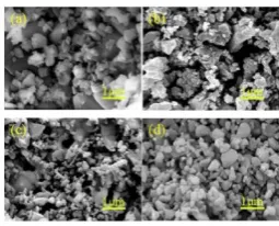
melting point of M-Si-O-N (M is rare earth) system, it is necessary to add a diluent in the powder to reduce the reaction temperature. In this paper, silicon nitride is used as a diluent. Figure 7 shows the effect of the diluent content on the microstructure of silicon nitride under the same sintering condition. Impact. It can be seen from Fig. 7 (a) that when no diluent is added, the sintered grains are very irregular. Because of the high reaction temperature, some abnormally grown grains and some glass phases are produced. With the addition of
diluent, the grain size decreases uniformly. It can be considered that the diluent reduces the reaction temperature effectively. When the content of diluent reaches 30wt%, the grain size is relatively uniform, and the maximum grain size is less than 1 micron. Microwave sintering itself, because of its short holding time, can inhibit the abnormal growth of grain to a certain extent. Additionally, the role of diluent makes silicon powder produce microcrystalline structure.
Fig.7 Effect of dilutent content on the micro structure (a) 0wt.%; (b) 10wt.%; (c) 20wt.%; (d) 30wt.%
Fig. 8 shows the effect of different re-sintering temperature and holding time on the microstructure of porous silicon nitride. For the 30-minute holding time, it can be seen from sub-graph b1 that only a small amount of long columnar β silicon nitride is produced, which has a certain porosity, indicating that the sintering temperature is 1450。C. A small
amount of α SILICON nitride is converted to β silicon nitride at 30 min of heat preservation at 1450。
C, which indicates that the diffusion rate of silicon nitride is slower at lower temperature, and the holding time is too short, resulting in a small amount of phase
transition. It can be clearly seen from the sub-graph b2 that a long columnar beta phase is
formed at 1500 。
C, which indicates that the phase transformation rate is faster than that of figure b1, and the porosity is larger, and the growth is disorderly. This is due to the existence of liquid phase which causes the aggregation of α SILICON nitride particles and the shrinkage of the green body, leading to the existence of macropore. As you can see from sub-graph B3, a large number of long columnar grains are interwoven and connected with each other, forming a network structure, which indicates that the growth of beta phase grains has filled the voids, indicating that at 1550 。
C phase transition rate is faster. [10]-[13]
7
Fig. 8 1450。C
,1500。C
,1550。C Re-sintered fracture appearance (b1)1450。C for 30min;
(b2)1500。
C for 30min; (b3)1550。
C for 30min; (b4)1450。
C for 60min; (b5)1500。
C for 60min; (b6)1550。
C for 60min; (d4)1450。
C for 90min; (d5)1500。
C for 90min; (d6)1550。
C for 90min
When the holding time is prolonged to 60 minutes, it can be seen from the sub-graphs b4, b5 and b6 that with the increase of temperature, the porosity on the surface decreases gradually and the distribution becomes homogeneous, and the original equiaxed crystals become long columnar crystals. These long columnar crystals are filled in the voids and densified gradually. It is obvious that some β-phase long columnar silicon nitride interlaces with each other to form a network structure. The pore size becomes smaller and smaller, and the strength increases accordingly. However, because the long columnar crystal network structure of silicon nitride does not bond as tightly as other materials, but grows loosely in the voids, the effect of toughening and strength improvement of ceramics is not very clear. This kind of microstructure just reflects the reason why the mechanical properties of the material are different from those of other materials. It can be seen from the fracture morphology that the fracture of β-phase silicon nitride grains is obvious. This phenomenon is due to the grain pull-out effect when the crack deflection occurs in β-phase silicon nitride grains, which can increase the crack propagation resistance and
enhance the strength of materials.
The holding time continues to extend to 90 minutes. With the increase of temperature, the surface morphology of d4, d5 and d6 shows that there are still large holes on the surface of the material. The degree of densification is small, the porosity is large, and the long column-shaped β-silicon nitride can still be seen. This indicates that the α phase has been transformed into beta phase, but needle-bar-like β-silicon nitride can not be seen. Because of the high sintering temperature, when the material is insulated, the β-silicon nitride phase can The grain size of β-phase silicon nitride becomes smaller and smaller because of the preferential orientation of β-phase silicon nitride in the growth process.
Mechanism analysis of microwave
sintering
porous
silicon
nitride
ceramics
8
vector can represent the polarization intensity. Generally speaking, with the increase of dielectrics, the polarization ability increases. We divide dielectric polarization into the following four forms: firstly, due to the existence of external electric field, the displacement between the outer electron cloud and the nucleus of the atom causes polarization; secondly, the displacement between atoms or ions constituting dielectric molecule corresponds to the polarization effect; thirdly, the couple of dielectric molecule itself exists in the absence of external electric field. Polar moments, however, exist in every direction, so the cumulative dipole moments are 0. Under the condition of the external field, the dipoles which are scattered in disorder will produce displacement and polarization. Fourth, the polarization of charges will often occur at the interface of two different media, thus forming interlayer or interfacial polarization. Correspondingly, in the external electric field, there are the following modes of motion of dielectrics: first, the thermal motion caused by the change of temperature; second, the dipole moments are arranged along the electric field under the action of the electric field force; third, all dipoles with rotational polarization have long-range forces, which interact with each other and cause a dipole to turn around at the
same time. Many dipoles rotate,
correspondingly, the dipoles around them can react on the former and make it change again. In the case of small external electric field force, thermal motion occurs within the molecule. From the solid point of view, it is the thermal motion around the molecule. On the contrary, when the polarizer is strong, it will promote the rotation of the polarizer, and then arrange along the direction of the electric field. When the external electric field reaches a certain intensity, the gas molecules will form thermal ionization, and then generate plasma. For solid media, there will be electrical breakdown phenomenon.
According to valence bond theory, the so-called chemical reaction is a process of separation of old bonds and generation of new bonds. In the process of separation of old bonds, the gravitation existing between atoms should be overcome. On the contrary, the generation of new bonds depends on the proximity of atoms. It is not difficult to see that both processes require higher requirements for the molecules involved in the reaction and need to have. Higher energy can weaken and separate molecular bonds, at the same time, support the barrier of migration and reaction, and produce new substances.
In microwave heating, silicon powders
consume microwave by a large margin due to the influence of electric field, resulting in
polarization of molecules. Molecular
9
shorter. Therefore, the smaller the particle size of the material used, the shorter the reaction period under the influence of microwave electric field. When the same number of reactions occur, only a lower temperature is needed, that is to say, finer materials can reduce the energy required for the reaction.
After reaching the critical temperature,
Birnboin and other scholars studied the distribution characteristics of the micro-electric field in the two dielectric sphere particles in contact. They believed that the electric field gathered at the sintering neck, where the electric field intensity was about ten times that of other parts, and the electric field intensity of the gap was about 30 times that of other parts. At the same time, when the angle between the field and the particle line is less than 80 degrees, the electric field polarizes along the line, which increases the mass transfer rate. In addition, under the influence of a large number of electric fields, the ionization at the sintering neck is stronger, which increases the mass transfer efficiency. Birnbion's research proves that microwave can accelerate sintering, in essence, because this kind of ionization phenomenon increases the mass transfer rate. Microwave volume heating can provide conditions for large-scale zero-gradient uniform heating in the sample, reduce the thermal stress of the sample, and avoid material cracks and deformation in the heating process. Because microwave can be absorbed by materials and transformed into heat energy, the energy required for sintering is reduced, and
about 20% of the energy can be saved.
The consumption factor of heating material increases sharply, which makes the temperature rise faster. At the same time, microwave reduces the energy required for the reaction, further accelerates the sintering process and greatly reduces the reaction time. Compared with traditional sintering, the shorter the sintering duration, the more stable the grain size, the stronger the homogeneity, the smaller the void volume and the better the roundness, the stronger the ductility and toughness, and the lower the sintering temperature.
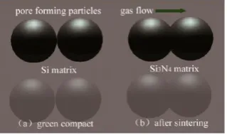
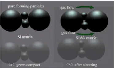
Fig. 9 and Fig. 10 are the same particle
reaction model in ordinary sintering and the reaction model of different size particles in this study. Taking Si3N4 as an example, the
principle is as follows: First, with the help of surface diffusion, evaporation-condensation, silicon powder diffuses to the reaction site, where chemical reaction occurs with nitrogen to form silicon nitride grains, and the silicon nitride grains produced in this process are adsorbed on silicon powder. In this process, the longer the reaction time, the slower the reaction speed. If the silicon nitride grains are completely covered with the silicon surface, the compression strain will cause the part of silicon nitride to fall off and the part of silicon surface to be exposed, thus the reaction can be sustained. At this time, the reaction area of silicon surface can be reduced and the reaction time increased. When silicon nitride is completely separated from nitrogen, the reaction terminates.
10
Fig. 10 Contacts of different size particles in this study
The comparison between microwave sintering and pressureless sintering of porous silicon nitride material is shown in
Fig. 11. From the figure, it can be seen that microwave sintering and pressureless
sintering have opposite thermal gradient: the surface temperature of pressureless
sintering is higher than that of center sintering, while the temperature of microwave sintering center is higher than that of surface sintering. This temperature gradient makes diffusion reaction occur from inside to outside. During the nitriding process of silicon powder, the inner silicon
powder is outward. In the process of diffusion, a diffusion channel from inside
to outside is formed inside the particles.
In pre-nitriding, the rare earth oxynitride coating on the surface of silicon powder makes the silicon powder with relatively uniform particle size become spherical when it is pre-nitriding, but in the process of microwave sintering and nitriding, because of the anisotropy of interfacial energy of silicon nitride, the interfacial energy of C axis is relatively low, and the spherical silicon powder is from the center of the particle. At the same time, the spherical silicon powder grows along the C axis, forming a beaded structure.[11]-[14]
Fig. 11 Comparision of SEM of pore Si3N4 at the microwave sintering and non-presses sitning the agglutination (a) microwave sintering; (b) non-presses sintering
Reaction Kinetics Calculation of
Porous Silicon Nitride Ceramics
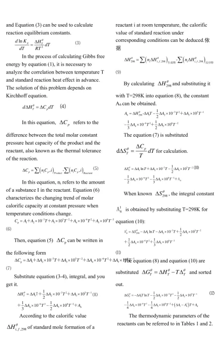
Gibbs-Helmholtz and Vant Hoff equations are general equations for chemical equilibrium based on standard reaction heat effect.
⑴
2 ln
T T
T p
G H
d dT
T T
G RT K
= −
= −
⑵
11
and Equation (3) can be used to calculate reaction equilibrium constants.
2
ln p T
d K H
dT dT RT
= ⑶
In the process of calculating Gibbs free energy by equation (1), it is necessary to analyze the correlation between temperature T and standard reaction heat effect in advance. The solution of this problem depends on Kirchhoff equation.
T p
d H = C dT ⑷
In this equation,
C
p refers to thedifference between the total molar constant pressure heat capacity of the product and the reactant, also known as the thermal tolerance of the reaction.
(
,)
-(
,)
Product
p i p i p Reactant
C n C i n C i
=
⑸In this equation, ni refers to the amount
of a substance I in the reactant. Equation (6) characterizes the changing trend of molar calorific capacity at constant pressure when temperature conditions change.
3 5 2 6 2 8 3
2 3 5
p 1 A 10 T A 10T A4 10 T A 10T
C =A+ − + −+ − + −
⑹
Then, equation (5)
C
pcan be written inthe following form
p 1
3 5 2 6 2 8 3
2 10 3 10 4 10 5 10
A T A T A T A
C A − − − T−
= + + + +
⑺
Substitute equation (3-4), integral, and you get it.
3 2 5 1
2 3
6 3 8 2
1
4 5 6
1 10 10 2 1 1 10 10 3 2
T A T A T
A T A T A
H A − −
− − − = + + + T + ⑻
According to the calorific value
, ,298
i f
H
of standard mole formation of areactant i at room temperature, the calorific value of standard reaction under
corresponding conditions can be deduced.依 据
(
)
(
)
298 i i f, ,298 - i i f, ,298
H n H n H
=
生成物 反应物
⑼
By calculating
H
298 and substituting itwith T=298K into equation (8), the constant A6 can be obtained.
3 2 5 1
6 298 1 2 3
6 3 8 2
4 5
1
- 10 10
2
1 1
10 10
3 2
A H A T A T A T
A T A T
− − − − = − − + +
The equation (7) is substituted
d
S
TC
pdT
T
=
for calculation.3 5 2
1 2 3
6 2 8 3
5 6
4
1
ln 10 10
2
1 1
10 10
2 3
T
S A T A T A T
A T A T
− − − − = − − − + +A ⑽
When known
S
298 , the integral constant1 6
A
is obtained by substituting T=298K forequation (10):
1 3 5 2
6 298 1 2 3
6 2 8 3
4 5
1
ln 10 10
2
1 1
10 10
2 3
S A T A T A T
A T A T
− − − − = − − A + + + ⑾
The equation (8) and equation (10) are
substituted
G
T=
H
T−
T
T and sortedout.
( )
3 2 5 1
1 2 3
6 3 8 2 1
4 5 1 6 6
1 1
ln 10 10
2 2 1 1 10 10 6 6 T T
G AT T A T A T
A T A T A A A
− −
− −
= − − −
− − + − +
⑿
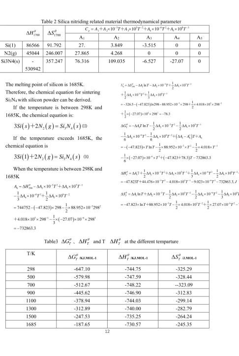
The thermodynamic parameters of the reactants can be referred to in Tables 1 and 2.
Table 1 Silica nitriding related material thermodynamical parameter
298
H
S
298
Cp A1 A2 103T A3 105T 2 A4 106T2 A5 108T 3− − − −
= + + + +
A1 A2 A3 A4 A5
12
N2(g) 0 191.502 27.865 4.268 0 0 0
Table 2 Silica nitriding related material thermodynamical parameter
1700 H
S
17003 5 2 6 2 8 3
1 2 10 3 10 4 10 5 10
p
C =A+A −T+A T−+A −T+A T−
A1 A2 A3 A4 A5
Si(1) 86566 91.792 27. 3.849 -3.515 0 0
N2(g) 45044 246.007 27.865 4.268 0 0 0
Si3N4(s)
-530942
357.247 76.316 109.035 -6.527 -27.07 0
The melting point of silicon is 1685K. Therefore, the chemical equation for sintering Si3N4 with silicon powder can be derived.
If the temperature is between 298K and 1685K, the chemical equation is:
( )
2
2( )
3 4( )
3
Si s
+
N
g
=
Si
N
s
⒀If the temperature exceeds 1685K, the chemical equation is
( )
2( )
3 4( )
3
S
i
1
+
2
N
g
=
Si
N
s
⒁When the temperature is between 298K and 1685K
(
)
(
)
3 2 5 1
6 298 2 3
6
5 1
3 8 2
4 5 3 2 6 3 10 10 1 10 10 3 1
744752 47.823 298 88.952 10 29 1 2 4.018 10 8 2 1
27.07 10 298 3
732863.3 298
A H A T A T
A T A T
− − − − − − − = − − = − − − − = − − + + + ( ) ( )
1 3 5 2
6 298 1 2 3
6 2 8 3
4 5
3 5 2
6 2
1
ln 10 10
2
1 1
10 10
2 3
1
326.5 47.823 298 88.952 10 298 4.018 10 298 2
1
27.07 10 298 78.3 2
S A T A T A T
A T A T
ln − − − − − − = − − = − − − − − = − A + + + + +
(
)
( ) ( ) ( )3 2 5 1
1 2 3
6 3 8 2 1
4 5 1 6 6
3 2 1
6 3
1 1
47
1 1
ln 10 10
2 2
1 1
10 10
6 6
47.82
.823 ln 88.952 10 4.018
2 2
1
27.07 10 3 78.3 732863.3
6
T
G A T T A T A T
A T A
T T T T
T T
T A T A A
− − − − − − − = − − − = − − − − − − − − − − − + + + +
3 2 5 1 6 3 8 2
2 3 4 5 6
3 2 5 1 6 3
1
1 1 1
10 10 10 10
2 3 2
47.823 44.476 10 4.018 10 9.023 10 732863.3,
T A T A T A T A T A
T A
T T J
H T − − − − − − − − = − − = − − + + + + + T
3 5 2 6 2 8 3
1 2 3 4 5
3 5 2 6 2
6
1 1 1
ln 10 10 10 10
2 2 3
1 1
ln 10 4.018 10 27.07 1
47.823 88.95 0 78.29,
2 2
2
T
S A T A T A T A T A T
T T T T J
− − − − − − − = − = − − − − −
+ +A
+ +
Table3
G
T
、H
T
and TH
T
at the different tempartureT/K
T
G
/KJ.MOL-1
H
T /KJ.MOL-1
S
T /J.MOL-1298 -647.10 -744.75 -325.29
500 -579.98 -747.59 -328.44
700 -512.67 -748.22 --323.09
900 -445.62 -746.90 -312.83
1100 -378.94 -744.03 -299.14
1300 -312.89 -740.00 -282.79
1500 -247.53 -735.25 -264.24
13
The calculation results of temperature below 1685K are shown in Table 3. If the temperature exceeds 1685K, the chemical equation is equation (14), which is taken as 1700K. Thermodynamic solution is carried out according to reaction 3-14. The specific steps are the same as above. The calculation results are shown in Table 4.
The relationship between the standard free energy of formation and temperature of silicon nitride is shown in Fig. 12. From the
observation and analysis of Fig. 12,
G
Tcanbe seen that the reaction can proceed
spontaneously in the whole calculation
temperature range, and the
G
T valuedecreases with the decrease of temperature. Based on the theory that the trend of reaction is negatively correlated with the change of
T
G
value, the conclusion that silicon nitridecan be synthesized at room temperature can be obtained. However, at lower temperatures, the synthesis rate is too slow to be realized in kinetics, so the actual sintering temperature is over 1200。
C.
Table 4
G
T 、
H
T and ' 1T
at the different tempartureT/K
T
G
/KJ.mol-lH
T
/KJ.mol-lS
T
/KJ.mol-l1700 -183.48 -880.73 -410.14
1800 -142.57 -877.56 -408.33
1900 -101.82 -874.35 -406.60
2000 -61.24 -871.17 -404.96
2100 -20.82 -868.06 -403.45
Fig.12 Standard production free energy of silicon nitride in 298~2100K At high temperatures, Si3N4
decomposes according to the reaction.
( ) ( ) 3 4s 3 2g Si N = Si+2N ⒂
The decomposition temperature of silicon nitride is related to N2 pressure. This section
seeks the relationship between nitrogen
pressure and decomposition temperature of silicon nitride.
On the basis of the first approximate calculation theory, it can be deduced that the value of the molar constant pressure heat
14
is zero, that is to say, the molar constant pressure heat capacity of the product and the reactant is balanced.
1700
1700
0 0
T p
T T T
d H C dT H
H H IT
= =
= =
+
By combining the same equation (1), we can get
1700
T
G
H
IT
=
+
If I is an integral constant, T = 1700K, then we get
1700 1700
1700 1700
G H
I S
−
= = −
(
)
(
)
1700 i T,1700 Product- i T,1700 Reactant
S n S n S
=
=3 91.792 2 246.007 357.27 =411.14
(
)
(
)
1700 ,1700
- ,1700
Product
Reacta i T
i T nt
H n H
n H
=
=3 86566 2 45044 530942 =880728, J
1700
T
G
H
IT
=
+
=880728- 411.14T
Reaction free energy under different
nitrogen pressure :
2
2
ln p,
T T RT K Kp N
G G =P
= +
When the reaction reaches equilibrium
T G =0,则 GT GT RTlnKp
= +
=880728 411.14 8.314
2
2
ln
P
N=0
The arrangement is as follows:
2
2 880728 411.14 8.314 ln N
T
P
=
−
Fig. 13 Relations of silicon nitride decomposition temperature and nitrogen pressure The calculation results are shown in Fig.
13. It can be found from Fig.13 that the decomposition temperature of silicon nitride can be increased by increasing the pressure of N2. The decomposition temperature of silicon
nitride is 2567.3K when sintered under 6 MPa atmosphere. The temperature range used in this study is 1700-1750K, and Si3N4 will not
decompose.
Mechanical properties of porous
silicon nitride ceramics
diameter-15
thickness ratio, the smaller the dielectric loss of materials. The reason of dielectric loss can be attributed to ionization loss and polarization loss. Among them, the main source of ionization loss is gas. When the external electric field intensity is higher than the electric field value necessary for the ionization of the gas contained in the solid medium, the energy consumption will be caused during the ionization process of the gas. Polarization loss is caused by particles. Under the action of electric field, particles resist thermal motion and cause consumption. This loss generally occurs in two types of dielectrics, i.e. ionic lattice loosening or dipole type dielectrics. As the ratio of diameter to thickness increases, the space occupied by the pore increases. Compared with the solid without conductivity, the electrical resistance and capacitance of the
gas are relatively small. As a result, the electric field strength of the gas part is higher than that of the insulating solid. Therefore, the probability of gas dissociation and loss in the pore is relatively high. From Figure 14, we can see that the dielectric loss of porous silicon nitride ceramics is relatively low, all in the order of 10-3.Low dielectric loss makes porous silicon nitride a candidate material for wave-transmitting dielectric ceramics. The dielectric constant of the material can be adjusted between 2 and 8. When the diameter-thickness ratio of the material is about 2.4, the minimum dielectric constant of the material is about 2. Porous silicon nitride ceramics with adjustable dielectric properties were prepared through this study, which laid a foundation for later application.[11]-[14]
Fig. 14 Effect of diammeter to deep on the dielectric
Summary of this article
In this paper, the preparation methods of porous silicon nitride materials with
controllable dielectric constant and pore structure were systematically studied. By using microwave sintering technology, porous silicon nitride materials with high closed pore ratio were prepared by adjusting the content of sintering additives and sintering process parameters, and controlling the grain
boundary phase and pore structure and size. The conclusions are as follows:
(1) The porous silicon nitride
ceramics prepared by microwave sintering process with silicon powder as raw
16
(2) With Sm2O3 as sintering additive, the bending strength of the material reaches 300 MPa when the content of Sm2O3 is 1.2 wt.% at the first nitriding temperature of 1200。
C and the second nitriding temperature of 1350。
C
respectively. With the increase of nitriding temperature, the weight gain rate of nitriding increases gradually. At 1350。
C, the final weight gain rate of nitriding is close to 66% of the theoretical weight gain rate.以
(3) The addition of diluent effectively reduces the reaction temperature, and the grain size is fine and uniform. When the diluent content is 30 wt.%, the grain size
is relatively uniform.
(4) When the total porosity is less than 60%, the bending strength
decreases slightly with the increase of the porosity, and the bending strength is about 50 MPa. With the increase of the total porosity, the bending strength increases obviously. When the porosity is 78%, the bending strength is 300 MPa; and when the total porosity is about 80%, the bending strength decreases again. The bending strength of porous silicon nitride material is closely related to the closed porosity, which varies with the change of the closed porosity.
Reference
[1] G. Partridge.Advance Materials, 2017, 12: 446.
[2] Dodds G C, Tanzilli R A.Article and method of making same.US5925585, 2018.
[3] Dodds G C, Tanzilli R A. Article and method of making same.US5925584, 2018. [4] Dodds G C, Tanzilli R A.
Article and method of making same. US5891815, 2018.
[5] Hsieh M Y. Low dieleetric loss silicon nitride based material.
US4654315, 2017.
[6] Talmy I G, Martin C A, Haught D A et al. Electromagnetic windou. US 5573986, 2016.
[7] Paqutte G D. USA, 5627542. 2017. [8] Favaloro M, Starett S, Bryanos J. In: 6th Do D EM Windows Symposium, 2016.
[9] E.M.M. Ewais, M.A.A. Attia, A. Abousree-Hegazy, et al. Ceramics International, 2017, 36 (4): 1327.
[10] Sreekumar Chockalingam, David A. Earl. Journal of the European Ceramic Society, 2018, 29 (10): 2037.
[11] Sriharsha Pasupuleti, Ramseshu Peddetti, et al. Materials Science
and Engineering: A, 2018, 491 (1-2): 224 . [12] Liu Ping, Li Yongfeng, Wang Xiangdong et al.Key Engineering
Materials, 2018, 434: 106.
[13] Gao Lian, Jin Xihai, Li Jingguo, et al.
Materials Science and Engineering A, 2016 (415): 145.