Distribution of material properties in finite
element models of inhomogeneous elements of
structures
Egor Moskvichev1,*
1Institute of Computational Technologies SB RAS, Krasnoyarsk Branch Office, Mira str. 53, 660049 Krasnoyarsk, Russia
Abstract. This paper discusses an approach to finite element modelling of structure elements considering material inhomogeneity. This approach is based on the functional dependence of mechanical properties on the spatial coordinates of finite elements. It allows modelling gradient transitions between different materials, which avoid stress discontinuities during strength analysis. The finite element models of cold formed angle, welded joint and thermal barrier coating, created by this method, have been presented.
1 Introduction
Many engineering and scientific problems of strength analysis require taking into account the material inhomogeneity. It occurs because the manufacturing technologies of many structural elements imply a gradual change in material properties or usege of several materials in one part. A forming, welding and coating can be considered as examples of such technologies. Cold formed sections have a difference in yield strength and residual strain along the contour due to large plastic deformations [1]. For welded joints, there are three zones with various material properties (base metal, heat-affected zone and weld metal) which are gradually changing from one to another [2, 3]. These effects are also typical for different coatings which may consist of metal and ceramic materials [4, 5]. To perform a strength analysis of these structural elements, numerical methods, such as finite element method, are often used. Thus, the finite element modelling considering material inhomogeneity is a task of current interest in structural analysis.
The basis for inhomogeneity modelling is the difference in material properties for various geometric regions of the model. In general, boundaries between regions may have sharp or gradual transitions. This leads to different approaches for modelling inhomogeneous elements of structures. The simplest finite element model with inhomogeneous material is shown in Fig. 1a. The disadvantage of this model is the discontinuity of stresses at the material boundary, which may not occur in reality. To avoid this, the model can be divided into a number of subareas with different properties, ensuring a smooth transition from one material to another as shown in Fig. 1b. However, this makes
the preparation of the finite element model more complicated and time-consuming because modern software products of finite element analysis do not offer ready-made solutions for creating such models. The following is an approach to solve this problem and to simplify the finite element modelling considering material inhomogeneity.
Fig. 1. The modelling approaches for boundaries a) with sharp transition, b) with gradual transition.
2 Model description
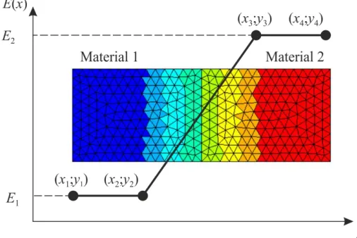
The essence of the proposed approach is to create an inhomogeneous model based on the existing finite element mesh of a homogeneous model. To do this, it is necessary to define the function, according to which finite elements of the model will have individual mechanical properties depending on their spatial coordinates. Usually, in structural elements with material inhomogeneity the material properties change along one direction. In this case, the function of the material properties will depend on one variable which determines the position of finite elements along the selected direction. In general cases, the function can be arbitrary, but in a scope of finite element analysis it seems acceptable to set it in a piecewise linear form. The example of the Young’s modulus distribution in the finite element model according to piecewise linear function is shown in Fig. 2.
Fig. 2. Young’s modulus distribution and its piecewise linear function.
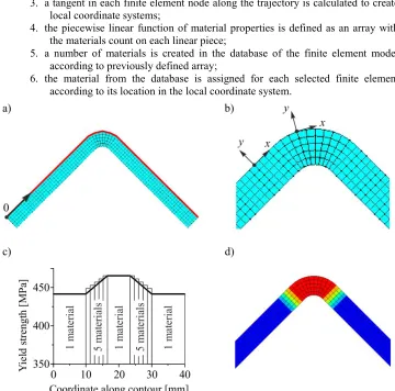
This approach was implemented as a program in Ansys Parametric Design Language. The program allows setting the material properties in finite element models along a curved path. The program algorithm is shown in Fig. 3 and consists of the following steps:
2. the origin of the spatial coordinate system and the trajectory along which the material properties will change are defined;
3. a tangent in each finite element node along the trajectory is calculated to create local coordinate systems;
4. the piecewise linear function of material properties is defined as an array with the materials count on each linear piece;
5. a number of materials is created in the database of the finite element model according to previously defined array;
6. the material from the database is assigned for each selected finite element according to its location in the local coordinate system.
Fig. 3. Program algorithm illustration a) steps 1, 2, b) step 3, c) steps 4, 5, d) step 6.
3 Model applications
The developed program was used to create finite element models of several elements of structures with material inhomogeneity. For these models the piecewise linear functions of material properties were based on specially held mechanical test and literature data.
Fig. 4. Cold formed angle a) test diagrams, b) function of the yield strength, c) finite element model.
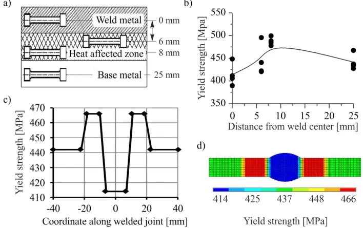
The modelling of inhomogeneous welded joints is more complicated problem. This requires more data on mechanical properties for different zones of a model. Such model was created on the basis of experimental data presented in the work [6]. During experiments tensile tests were held for series of specimens from the double-sided welded joint of 09G2S (9MnSi5) steel. The specimens were cut from base metal, heat-affected zone and weld metal (Fig. 5a). The resulting function of yield strength (Fig. 5c) along the welded joint was used to create the finite element model with material inhomogeneity (Fig. 5d).
Further application of the presented approach was the modelling of thermal barrier coating system with defect shape [7]. The system consists of several material layers which significantly differ by Young's modulus, Poisson's coefficient and coefficient of thermal expansion. Considering the material properties presented in [8-10], three piecewise linear functions (Fig. 6) associated with the finite element model of coating were defined for different temperatures.
Fig. 6. Material functions of the coating system a) Young's modulus, b) Poisson's coefficient, c) coefficient of thermal expansion.
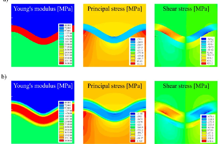
The numerical analysis of residual thermal stress during cooling was run for two finite element models of the coating system. The homogeneous model had sharp transitions between layers, which led to stress discontinuous in the results (Fig. 7a). The inhomogeneous model (Fig. 7b) had gradient transitions between layers considering the piecewise linear functions of material properties. In this case the resulting stress field was smooth and differed in maximum values comparing to homogeneous case. Thus, the material inhomogeneity can significantly changes the stress distributions in finite element models that may have a great importance during strength analysis of particular elements of structures.
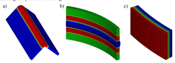
The finite element models presented above are applicable for two-dimensional cases. However, the considered algorithm can be successfully applied to three-dimensional models of structural elements. Examples of 3D finite element models with material inhomogeneity are shown in Fig. 8.
Fig. 8. 3D finite element models a) cold formed beam, b) welded tank shell, c) thin-wall coating.
4 Conclusions
The paper presents the method for numerical modelling considering material inhomogeneity. The proposed method can be useful for refined finite element analysis of different types of structural elements. The method requires detailed information on material properties which can be obtained combining mechanical tests and microindentation. Analysing the results obtained for model of thermal barrier coating system, it was found that the material inhomogeneity can significantly effect on stress field. This determines the possible expediency of considered models in strength analysis.
References
1. K.W. Karren, J. Struct. Div. – ASCE, 93, 401 (1967)
2. M. Kocak, 63rd Annual Assembly & International Conference of the International Institute of Welding, 3-19 (2010)
3. D.W. Rathod, S. Pandey, P.K. Singh, R. Prasad, J. Pressure Vessel Technol. Trans. ASME, 138 (2015)
4. K. Ma, H. Xie, J. Zhu, H. Wang, Surf. Coat. Technol., 253, 58-67 (2014) 5. Z.A. Opiekun, Superalloys (IntechOpen, 2015)
6. E. Moskvichev, Key Eng. Mater., 592-593, 173-176 (2014)
7. E. Fedorova, A. Burov, N. Sukhodoeva, V. Moskvichev, Procedia Struct. Integrity, 13, 741 (2018)
8. J.A. Haynes, B.A. Pint, W.D. Porter, I.G. Wright, Mater. High Temp., 21 (2004) 9. R.G. Munro, J. Am. Ceram. Soc., 80, 1919-1928 (1997)