MATLAB Realisation of SVPWM Based
Speed Control of Asynchronous Machine Fed
From Solar Cell Array
Seemant Chourasiya
1, Khushboo Gupta
2, Seema Agarwal
3PG Student [PE&ED], Dep. of EE, University College of Engineering, Kota, Rajasthan, India 1 PG Student [PE&ED], Dep. of EE, University College of Engineering, Kota, Rajasthan, India 2 Assistant Professor, Dep. of EE, University College of Engineering, Kota, Rajasthan, India 3
ABSTRACT:The lake of Conventional resources and high cost of electrical energy production form oil, gas and coal lead to the development and enhancement of new alternate energy sources like solar, wind, tidal etc. The solar energy sources best advantage is environmental friendly and enormous source of huge amount of energy. This energy operating cost is also cheap and easy to setup in domestic and industrial purposes. This paper is mainly Focuses on MATLAB/ SIMULINK model of Space Vector controlled Asynchronous Motor Using Solar cell Array. The reason to choose MATLAB / SIMULINK as a development tool is because it is the most widely used software in Electrical Engineering. The Solar cell simulation model has been developed in the Sim Electronics Tool box and SVPWM based speed control model has been developed in Sim Power System Tool box. These two different tool models are connected through PS-SIMULINK converters. In this paper we are controlling the speed of asynchronous motor using SVPWM and motor is operated through Solar cell array. We are using 3-level inverter to convert DC to DC converter output into AC voltage. This inverter output is fed into asynchronous motor. Inverter gate pulses are generated through SVPWM.
KEYWORDS:Solar cell Array, DC to DC converter, 3-level inverter, asynchronous motor SIMULINK converters.
I.INTRODUCTION
Energy is the basic need of a human life and it plays a very important role for the economical development of any Country. For the environment point of view, the big disadvantages of conventional energy sources are of their pollution. The renewable energy sources are free from pollution. Solar energy is the biggest alternative source of electrical energy and has a potential of about 178 billion MW which is about 20,000 times of the world energy demand. It has disadvantage of large space requirement to establish it. India is a country where sun light is always present throughout the major part of the year [2].
Figure 1: A Proposed Block diagram of Simulation
II. SOLAR CELL ARRAY MODULE
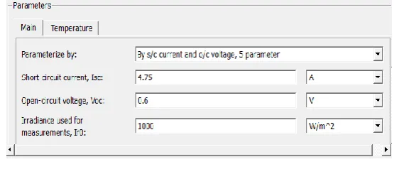
Solar cell is basically a PN junctions in which the light is incident and the electromagnetic radiation of sun is directly convert into electricity through Photovoltaic effect. In this paper for making Solar cell array 72 cells are connected in series. The block model of solar cell is a parallel combination of Current source, two diodes and a parallel resister Rp in series with the resistance Rs. The output current equation of solar cell is given by
I = Iph - Is*(e^ ((V+I*Rs)/(N*Vt))-1) - Is2*(e^((V+I*Rs)/(N2*Vt))-1) - (V+I*Rs)/Rp Here I = output current
Is and Is2 = diode saturation currents Vt = thermal voltage
N and N2 = quality factors (diode emission coefficients) Iph = solar-generated current
the parameters of the solar cell are shown in the figure 2.
Figure 2: Solar cell parameters
72 solar cells are connected in series to get the output of 23.75 V.
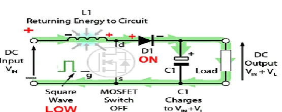
III. DC-DC CONVERTER
pulse-width-modulation (PWM) switching technique. The switching duty cycle, k is defined as the ratio of the ON time to the total switching time period. The output voltage of the boost converter is
𝑉𝑜𝑢𝑡= 1 1−𝑘 Vs
Where is k = Duty Cycle
Figure 3: Basic circuit diagram of boost converter
IV. INVERTER CIRCUIT
Now a day's generation is mainly depends on renewable energy sources. Most of these generate the electricity in DC so that our maximum Loads are working on Ac. So it is very important that we have to convert DC into AC. It is done by power electronics converter called Inverter. By choosing Appropriate modulation index and control of static switches of inverter the voltage and frequency levels are varied. The extensive use of SVPWM technique is because of it's digital implementation and maximum utilization of DC bus voltage. 3 phase inverter is having 8 switching states in that 2 are null states and 6 are active states which are used to control the inverter output voltage and frequency.
For the study of SVPWM technique 3 Phase coordinate system is converted in to 𝛼 − 𝛽 Plane. In this technique the referring voltage vector 𝑉𝑟𝑒𝑓 that rotates in the space with an angular velocity w is selected as a control instruction.
When it arrives in one of the 6 sectors 1~6, two effective voltage space vectors nearest to 𝑉𝑟𝑒𝑓 as well as one of the two
null vectors (V0 or V1) are selected to equal 𝑉𝑟𝑒𝑓 by means of different operating time of various vectors, and the
power switches in the inverter are drove under the switch conditions corresponding to selected vectors, (000, 001,...or 111), “0” for off and “1”. The inverter outputs a cycle of sinusoidal voltage when 𝑉𝑟𝑒𝑓 has made one revolution in space.
A. SVPWM ALGORITHEM STEPS
SVPWM methods have fallowing steps: 1. Determination of 𝑉𝛼, 𝑉𝛽, 𝑉𝑟𝑒𝑓 and angle (α).
2. Determination of time durations𝑇1, 𝑇2 , 𝑇0
3. Determination of switching times of the switches Step – 1:- Determination of 𝑉𝛼, 𝑉𝛽, 𝑉𝑟𝑒𝑓 and angle (α).
Space vector is defined as,
𝑉𝑆 = 2
3 (𝑉𝐴 + α 𝑉𝐵 + 𝛼 2𝑉𝐶 )
Where α = 𝑒−𝑗 2𝜋3
By the principle of SVPWM 𝑉𝛼 and 𝑉𝛽 are obtained by
𝑉𝛼
𝑉𝛽 =
2 3
1 −1/2 −1/2
1 √3
2 −
√3 2
𝑉𝐴 𝑉𝐵 𝑉𝐶
Here 3-phase quantities are reduced to two phase, one is direct axis (real axis) and other is quadrature axis (imaginary axis). These two quantities represented as the magnitude (𝑉𝑟𝑒𝑓) and angle (w). 𝑉𝑟𝑒𝑓 Rotates with the speed of angular
sectors spanning 60°each. The reference vector which represents three-phase sinusoidal voltage is generated using SVPWM by switching between two nearest active vectors and zero vectors.
Figure 4: Representation of space vector in complex plane
The 𝑉𝑟𝑒𝑓 and angle α is given by:
𝑉𝑟𝑒𝑓 = 𝑉𝛼2+ 𝑉𝛽2 and α = 𝑡𝑎𝑛−1 𝑉𝛽 𝑉𝛼
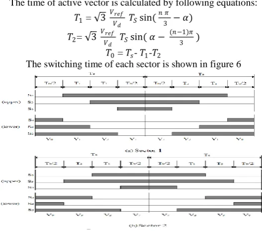
Step- 2:- Determination of time durations 𝑇1, 𝑇2 , 𝑇0 To calculate the time of application of different
vectors, consider Figure 5, depicting the position of different available space vectors and the reference vector in the first sector.
Figure 5: principles of space vector time calculations
The time of active vector is calculated by following equations:
𝑇1 = √3 𝑉𝑟𝑒𝑓
𝑉𝑑 𝑇𝑆sin(
𝑛 𝜋
3 − 𝛼)
𝑇2= √3 𝑉𝑟𝑒𝑓
𝑉𝑑 𝑇𝑆sin( 𝛼 −
(𝑛−1)𝜋
3 )
𝑇0 = 𝑇𝑠- 𝑇1-𝑇2
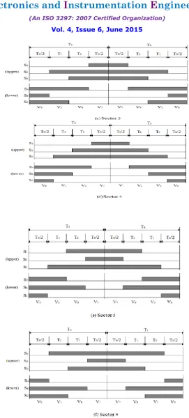
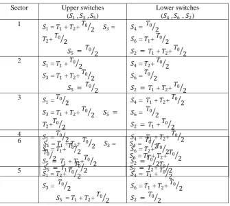
TABLE 1: Switch time calculations
Here in this model we are using reference speed for the generation of SVPWM.
V. MATLAB SIMULATION of PV ARRAY FED ASYNCHRONOUS MOTOR
In this model by using SVPWM the speed of motor is controlled. Reference speed is the most advantage to give SVPWM to control the inverter Switches.
Figure 7: 6 solar cell connected in series
All the solar cell array are connected in series to get better output voltage.
3 Ne g a ti ve
2 p o si ti ve
1 Irra d i a n ce
Ir +
- S o l a r Ce l l 5
Ir +
- S o l a r Ce l l 4
Ir +
- S o l a r Ce l l 3
Ir +
- S o l a r Ce l l 2
Ir +
- S o l a r Ce l l 1
Ir +
- S o l a r Ce l l
Sector Upper switches
(𝑆1 , 𝑆3 , 𝑆5)
Lower switches (𝑆4 , 𝑆6 , 𝑆2) 1
𝑆5 = 𝑇0 2 𝑆1 = 𝑇1 + 𝑇2+ 𝑇0 2 𝑆3 =
𝑇2+ 𝑇0 2
𝑆4 = 𝑇0 2
𝑆6 = 𝑇1+ 𝑇0 2
𝑆2 = 𝑇1 + 𝑇2+ 𝑇0 2
2
𝑆5 = 𝑇0 2 𝑆1 = 𝑇1 + 𝑇0 2
𝑆3 = 𝑇1 + 𝑇2+ 𝑇0 2
𝑆4 = 𝑇2+ 𝑇0 2
𝑆6 = 𝑇0 2
𝑆2 = 𝑇1 + 𝑇2+ 𝑇0 2
3 𝑆
1 = 𝑇0 2
𝑆3 = 𝑇1 + 𝑇2+ 𝑇0 2 𝑆5 =
𝑇2+𝑇0 2
𝑆4 = 𝑇1 + 𝑇2+ 𝑇0 2
𝑆6 = 𝑇0 2
𝑆2 = 𝑇1 + 𝑇0 2
4 𝑆
1 = 𝑇0 2
𝑆3 = 𝑇1+ 𝑇0 2
𝑆5 = 𝑇1 + 𝑇2+𝑇0 2
𝑆4 = 𝑇1 + 𝑇2+ 𝑇0 2
𝑆6 = 𝑇2+ 𝑇0 2
𝑆2 =𝑇0 2
5 𝑆1 = 𝑇2+ 𝑇0 2 𝑆3 = 𝑇0 2
𝑆5 = 𝑇1 + 𝑇2+ 𝑇0 2
𝑆4 = 𝑇1 + 𝑇0 2
𝑆6 = 𝑇1 + 𝑇2+ 𝑇0 2
𝑆2 = 𝑇0 2
6 𝑆1 = 𝑇
1 + 𝑇2+ 𝑇0 2 𝑆3 = 𝑇0
2
𝑆5 = 𝑇1 + 𝑇0 2
𝑆4 = 𝑇0 2
𝑆6 = 𝑇1 + 𝑇2+ 𝑇0 2
Figure 8: DC to DC converter
This is the boost converter circuit which can be used to boost up the solar cell array output voltage.
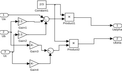
Figure 9: 3 phases to 2 phase conversion
This is the circuit which used to convert 3 phase ABC in to 2 phase conversion (dq). This technique can be used for reduced the mathematical calculations.
Figure 10: Complete Model
VI. SIMULATION RESULTS
For this developed model some of the results are taken for solar cell array, DC-DC converter, and inverter, output waveform of reference current generation through SVPWM technique and motor current and torque.
1 OUTPUT v + -Voltage Measurement
Series RLC Branch4 Series RLC Branch2
Series RLC Branch
Scope Pulse Generator g m C E IGBT1 Display Diode1 s -+
1 control signal
2 Ubeta 1 Ualpha Product2 Product1 -K-Gain4 -K-Gain3 0.5 Gain2 0.5 Gain1 2/3 Constant1 3 Uc 2 Ub 1 Ua SOLAR ARRAY SOLAR_CELL Discrete, Ts = 5e-005 s.
motor 2 motor Wm2 V + -V_inverter -K-V Vabc Iabc A B C a b c Three-Phase V-I Measurement Step f(x)=0 PS S SVPWM + -Resistor
Ref. Speed (rps) Ualf a Ubeta pulse PULSE GENERATION PS S PS S g A B C + N -Inverter I_inverter f(u) Fcn3 f(u) Fcn2 f(u) Fcn1 -K-F control signal OUTPUT
DC to DC converter
I
+
- s
-+ s -+ 1000 Clock m A B C Tm Asynchronous Machine SI Units |u| |u| IRRADIANCE POSITIVE NEGATIVE Ua Ub Uc Ualpha Ubeta 3 Phase to 2 Phase
conversion
Figure 11: Solar cell Output
This voltage, current and power of 72 cell solar array. The output of this solar cell array is 23.75 V.
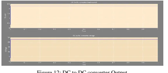
Figure 12: DC to DC converter Output
This is the output of boost converter which boosts the voltage of solar cell array.
Figure 13: SVPWM generation
This is the reference current generation for 3 level inverter through SVPWM. The input of SVPWM is reference speed of asynchronous motor.
This is the 3 level output of inverter.
Figure 15: 3-Phase Current of inverter
It is three phase current of inverter which is given to the motor.
Figure 16: 3-Phase Motor Currents
It is the stator current of 3 phases of motor.
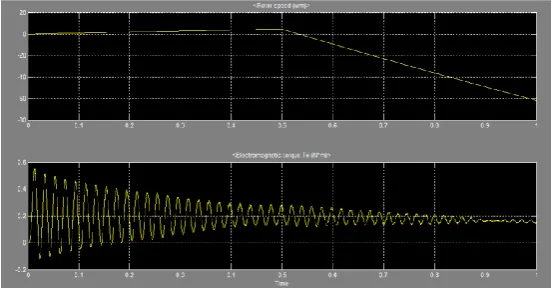
FIGURE 17:3-PHASE MOTOR TORQUE AND ROTOR SPEED
It is the torque and rotor speed of induction motor.
VII. CONCLUSION
In this paper a simple MATLAB / SIMULINK model has been presented to implement SVPWM based speed control
REFERENCES
[1] Kun Ding, XinGao Bian, HaiHao Liu and Tao Peng, "A MATLAB-Simulink-Based PV Module Model and Its Application Under Conditions of Non uniform Irradiance", IEEE Transaction on Energy Conversion, vol. 27, no.4, December 2010.
[2] M.G. Villalva, J.R. Gazoli and E. Ruppert F., " Modelling and Circuit-Based Simulation of Photovoltaic Arrays", Brazilian Journal Power Electronics, vol.14, no.1, pp. 35-45, ISSN 1414-8862, 2009.
[3] I.H. Altas and A.M. Sharaf, " A Photovoltaic Array Simulation Model for Matlab-Simulink GUI Environment", International Conference on Clean Power, pp. 341-345, 2007.
[4] Choung, S.H.; Kwasinski, A. "Multiple-input DC-DC converter topologies comparison", IEEE, IECON 2008, 10-13 Nov. 2008 Page(s):2359 - 2364
[5] Marian. K., Kazimierczuk, "Pulse-width Modulated DC-DC Power Converters", 2008 John Wiley & Sons, Ltd
[6 K.L. Zhou, and D.W. Wang, "Relationship between space vector modulation and three-phase carrier-based PWM: a comprehensive analysis," Industrial Electronics, IEEE Transactions on, vol. 49, pp.189-196, 2002.
[7]] B. Mirafzal, M. Saghaleini and A.K. Kaviani, "An SVPWM-Based Switching Pattern for Stand-Alone and Grid-Connected Three-Phase Single-Stage Boost Inverters," Power Electronics, IEEE Transactions on, vol. 26, pp.1102-1111, 2011.
[8] P. M. Meshram, Dipesh Hanote, M. M. Renge.∥ A Simplified Space - Vector PWM for Three Level Inverters Applied to Passive and Motor Load
∥, 978-1-4244-2800-7/09/$25.00 ©2009 IEEE.
[9] Wei-Feng Zhang and Yue-Hui Yu, "Comparison of Three SVPWM Strategies" In journal of electronic science and technology of china ,volume No:3 september 2007 page number 283-287
[10] Y. Zhang and J. Zhu, "Direct torque control of permanent magnet synchronous motor with reduced torque ripple and commutation frequency," IEEE Trans. Power Electron., vol. 26, no. 1, pp. 235-248, Jan. 2011
[11] Y. Zhang and J. Zhu, "A novel duty cycle control strategy to reduce both torque and flux ripples for DTC of permanent magnet synchronous motor drives with switching frequency reduction," IEEE Trans. Power Electron., vol. 26, no. 10, pp. 3055-3067,Oct. 2011.
[12] S. A. Zaid, O. A. Mahgoub, and K. El-Metwally, "Implementation of a new fast direct torque control algorithm for induction motor drives," IET Electr. Power Appl., vol. 4, no. 5, pp. 305-313, May 2010. [13] XudongWang, Ning Liu, and Risha Na, "Simulation of PMSM field oriented control based on SVPWM", Vehicle power and propulsion conference ,2009.
[14] G. S. Buja and M. P. Kazmierkowski, "Direct torque control of PWM inverter-fed AC motors-A survey," IEEE Trans. Ind. Electron., vol. 51, no. 4, pp. 744757, Aug.2004.
[15] D. Casadei, F. Profumo, G. Serra, and A. Tani, "FOC and DTC: Two viable schemes for induction motors torque control", IEEE Trans. Power Electron., vol.17, no. 5, pp. 779787, Sep. 2002
[16] K. B. Lee and J. H. Song, "Torque ripple reduction in DTC of induction motor driven by three-level inverter with low switching frequency," IEEE Trans. Power Electron., vol. 17, no. 2, pp. 255-264, Mar. 2002.
[17] C. Lascu, I. Boldea, and F. Blaabjerg, "A modified direct torque control for induction motor sensor less drive," IEEE Trans. Ind. Appl., vol. 36, no. 1, pp. 122-130,Jan./Feb. 2000 [9] M. Depenbrock, "Direct self-control (DSC) of inverter-fed induction machine,"IEEE Trans. Power Electron., vol. 3, no. 4, pp. 420-429, Oct. 1988.
[18] I. Takahashi and T. Noguchi, "A new quick-response and high-efficiency control strategy of an induction motor" IEEE Trans. Ind. Appl., vol. IA- 22, no. 5, pp.820-827, Sep. 1
BIOGRAPHY
Seemant Chourasiya was born in Kota, India, in 1989. He received the B. Tech Degree in Electrical Engineering in 2012 from LIET, Alwar and pursing M. Tech in Power Electronic and Electrical Drives from Rajasthan Technical University Kota. His research includes power electronic for renewable energy and electrical machine and power quality and Shunt active power filters.
KHUSHBOO GUPTA was born in Kota, India, in 1989. He received the B. Tech Degree in Electrical Engineering in 2011 from GWECA, Ajmer and pursing M. Tech in power electronic and Drives from Rajasthan Technical University Kota. His research includes power electronic for renewable energy and electrical machine and inverters.