A Novel Approach of Finger Print
Recognition Using (Ridge) Minutia Method
and Multilayer Neural Network Classifier
Devendra Singh Kaushal
1, Yunus Khan
2& Dr. Sunita Varma
31
Department of CSE
Jawaharlal Institute of Technology Borawan Khargone M.P. India [email protected]
2
Department of CSE
Jawaharlal Institute of Technology Borawan Khargone M.P. India [email protected]
3
Department of CTA
Shree G.S. Institute of Technology and Science Indore M.P. India [email protected]
Abstract:Finger print recognition has always been a
challenging field for the researchers. Fingerprint recognition is a biometric identification technology that distinguishing whether two fingerprints are the same fingerprint. There has been anastounding progress in the development of the systems for finger print recognition. Finger print recognition is the process of identification and classification of finger print using some classification and feature extraction method. The finger print recognition processcan have several stages like preprocessing, training,testing, recognition and post processing. The recognitiongenerally, consists of feature extraction and classification. The choice of feature extraction and classification schemeaffects the performance of recognition largely. In this paper, we implement finger print recognition scheme with multilayer neural network and minutia method for the feature extraction. This approach we extracted 80 features of every image using ridge scheme of minutia method of feature extraction and multilayer neural network for the classification and recognition of finger print. In this paper we describe how to implement each functional which we explained in functional specification. This design is in high level software design, it includes architectural design, data design interface design and procedural design.
Keywords:Multi-Layer neural network, Feature extraction, Ridge,
1.
Introduction
Fingerprint is one of the popular ways in human being identification. Fingerprint recognition is a biometric identification technology that distinguishing whether two fingerprints are the same fingerprint. The theory of fingerprint recognition is finding out minutiae (bifurcation and ridge) of two fingerprints, comparing them depend on their direction, local position and type. This project is Fingerprint recognition system. It is software that will work the same fingerprint recognition theory in computer. This system will compare two fingerprints image to make sure whether they came from the same finger. Fingerprint recognition system will implement fingerprint recognition theory base one image pre-processing technique and image recognition technique.
1.
Low level design
The low level design explains what the project will do and what the project looks like. The contents of this part show the domain layer of the project. It includes use case diagram, brief use case and system sequence diagram and domain model.
1.1.
Use case diagram
Figure 1.1 Use Case Diagram
1.2.
Brief use case
Use case: load image
Actor: user
Description: This use case begins with a user wants to load a fingerprint image in system. User can load the fingerprint image from an external image file or capture a fingerprint image from a fingerprint scanner.
Use case: Image pre-processing
Actor: user
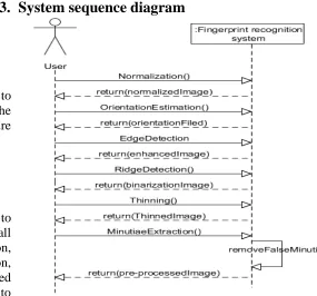
Description: This use case begins with a user wants to pre-process a fingerprint image. This part includes all operation of image pre-processing: normalization, orientation estimation, edge detection, ridge detection, and thinning and minutiae extraction. After loaded image, user has to click these buttons one by one to finish the pre-processing.
Use case: Image pre-processing
Actor: user
Description: This use case begins with a user wants to match two fingerprint images. After these two images have pre-processed, system will rotate both of them and then match their minutiae.
Use case: Database management
Actor: user
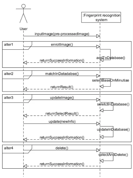
Description: This use case begins with a user wants to enroll a fingerprint/match a fingerprint to database/update fingerprint information/ delete a fingerprint. For enroll, system will add fingerprint information to database. For match in dataset, system will select a fingerprint in database for user. For update, system will select fingerprint information which user preference, and then allow user to change its information, but user cannot change its minutiae information. In delete fingerprint information, system will select fingerprint information which user preference, and then allow user to delete it.
1.3.
System sequence diagram
1.3.1.
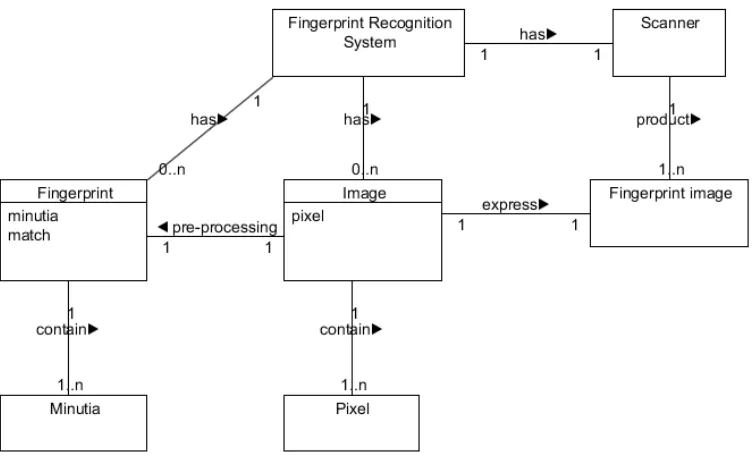
Domain model
Figure 1.5 Domain model diagram
2.
High level design
This part shows the idea of how I design to implement this project.
2.1.
Architectural Design
The main idea in this part is that comprising the system with a number of components, and the components are divided into six: User Interface module, Image loading module, Image pre-processing module, Image recognition module database management module and database module. Each module can be comprised into several sub-modules. In this part, I will describe them in detail. The main frame work of entire system
architectural is showed in figure 2.1. Figure 2.1 Main Frame of System architectural
been transformed between user and database in database management module. After image pre-processing, user can do the image recognition or enroll fingerprint information in to database through database management module. In Image recognition module, system gets the image data from image pre-processing module and gets the template image data from database. This is the main relationship between each module. Each module will be described in the following parts.
2.1.1 User Interface module
User interface module contains the main operation of this system. Through user interface, data can access Image loading module, Image pre-processing module, Image recognition module and database management module. These four modules’ result will display to user in user interface module.
2.1.2 Image loading module
User can import the external image data in this module. In this section, it allows user to load the image from external image file and also allows user to capture the image file from fingerprints scanner. The loading image is bmp type image.
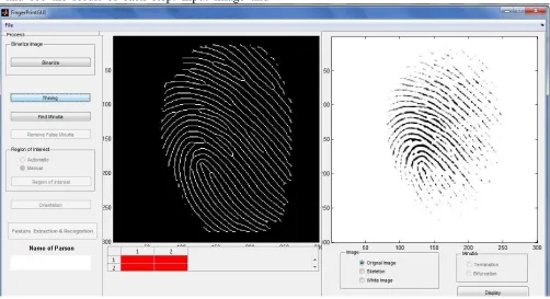
2.1.3 Image pre-processing module
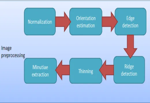
In this module, user can do pre-processing for an image. The goal of this module is to make the input fingerprint image suitable for recognition. In this module system get the original image data from image loading module. This module can be divided into six sub-modules: Normalization, Orientation estimation, Edge detection, Ridge detection, thinning and Minutiae extraction. Each sub-module instead each steps in image pre-processing. Figure 2.2 shows the relationship between each module. System will run these sub-modules one by one. After this module, an image is ready for recognition. Description of each sub-module is showed following:
Normalization: In this sub-module, fingerprint image will become a gray image. The result is a gray image with an excepted average gray level and an excepted variance.
Orientation estimation: This sub-module is calculating the orientation file of a fingerprint image.
Edge detection: The goal of this sub-module is to keep
the useful data, and throw the noisy point of an image. Ridge detection: The goal of this sub-module is to separate the background and foreground. The data of this module came from edge detection module.
Thinning: In this module, data came from ridge detection module. All ridges will be thinned into a 1 pixel weight line.
Minutiae extraction: This is the last sub-module in Image pre-processing module. In this module, system extracts minutiae from a thinned image. After minutiae extraction, system will check the minutiae and remove the false minutiae to keep the matching algorithm accurate. In order to show these two processes, I will show two results in user interface, one is minutiae extraction and another one is after false minutiae extraction.
Figure 2.2 Sub-modules in Image pre-processing module
2.1.4 Image recognition module
module, each fingerprint has been rotated into a format position (fingerprint is perpendicular in the image). The last module is minutiae matching module. This sub-module implements the recognition function. The relationship between each sub-module in image recognition module shows in figure 2.3.
Figure 2.3 Sub-modules in Image recognition module
2.1.5 Database management module
In this module, the main goal is allowing user to do the operation in database. For example enroll fingerprints
information into database. Note that the image information data include minutiae information. All data in database is after image pre-processing. User cannot enroll a fingerprint which is un-processing.
2.1.6 Database module
This module is physical database, it records the minutiae and fingerprint information.
3.2. Data Design
2.2.1 Data structure design
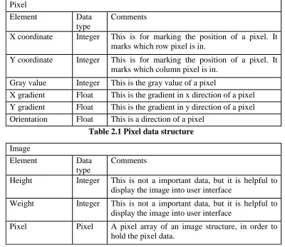
Array is the basic data structure in this system. Almost data is storage into an array. In image pre-processing, the main data is image data; there are two structures to hold an image data in image pre-processing: Pixel and Image. Pixel is for explain the image, and the image structure is to hold the data in image pre-processing. These two kinds of structures design as table 3.1 and table 2.2.
Pixel
Element Data type
Comments
X coordinate Integer This is for marking the position of a pixel. It marks which row pixel is in.
Y coordinate Integer This is for marking the position of a pixel. It marks which column pixel is in.
Gray value Integer This is the gray value of a pixel
X gradient Float This is the gradient in x direction of a pixel Y gradient Float This is the gradient in y direction of a pixel Orientation Float This is a direction of a pixel
Table 2.1 Pixel data structure
Image
Element Data type
Comments
Height Integer This is not a important data, but it is helpful to display the image into user interface
Weight Integer This is not a important data, but it is helpful to display the image into user interface
Table 2.2 Image data structure
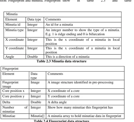
In image recognition, the main data is to explain fingerprint information. There are two data structures in image recognition: Fingerprint and minutia. Fingerprint
is for fingerprint data information and minutia is for minutia data information. These two kinds of structure show in table 2.3 and table 2.4
Minutia
Element Data type Comments
Minutia id Integer An id for a minutia
Minutia type Integer An integer number to show the type of a minutia. E.g. 1 is ridge ending and 0 is bifurcation
X coordinate Integer This is the x coordinate of a minutia in local position
Y coordinate Integer This is the x coordinate of a minutia in local position
Angle Double This is a direction of a minutia
Table 2.3 Minutia data structure
Fingerprint
Element Data type
Comments
Fingerprint image
Image A image structure identified in pre-processing
Core position x Integer X coordinate of a core Core position y Integer Y coordinate of a core
Delta Double A delta angle Number of
minutiae
Integer Show how many minutiae this fingerprint has
Minutiae Minutia[] A minutia array to hold minutiae data in fingerprint
Table 2.4 Fingerprint data structure
2.2.2 Database design
In this application, data will be storage into database. The main data is image data, fingerprint data and minutiae data. The image data in database is record twice, one is original one and one is pre-processed one.
Each image has been recorded with an id. In database, the main table is design for record fingerprint and minutiae data. Each tables design as table 2.5 and table 2.6.
TABLE_FINGERPRINT Field name Data
type
Comments
ORIG_IMAGE_ID Integer An id for find out the original image
PROCESSED_ IMAGE_ID
Integer An id for find out the processed image
DELTA Double A delta angle of a fingerprint image DESCRIPTION String A description of a fingerprint
Table 2.5 fingerprint table in database
TABLE_MINUTIA Filed name Data
type
Comments
MINUTIA_ID Integer An id for identify a minutia. Primary key
FINGEPRINT_ID Integer An id for shows fingerprint which this minutia belongs
POSITION_X Integer X coordinate in local position POSITION_Y Integer Y coordinate in local position DIRECTION Double A angle of a minutia
Table 2.6 minutia table in database
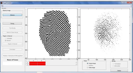
3.3. Interface Design
Figure 2.4 Main Frame of Fingerprint recognition system
In my application’s main frame, User click the capture/load button can load the image by two different ways. Before loading the image, user need to choose which image (input image or template image) should be loaded. After image was loaded, user can do the image pre-processing next. Each step in pre-processing allocation a button. User can click the button one by one and see the result of each step. Input image and
template image will do the pre-processing at the same time, user does not need to click every button twice. After pre-processing, user can do match through clicking the match button. The result will display in Match result panel. User can go to the database management through clicking the system menu in top of this window. Figure 3.5 is the enroll window.
Figure 2.5 Enroll Frame of Fingerprint recognition system
In this window, user can enroll a fingerprint or match a fingerprint in database. User does not need to do pre-processing step by step (Note that before enroll/match, image must do image pre-processing). User can choose “Auto processing” to let system do pre-processing
Figure 2.6 Fingerprint management Frame of Finger print recognition system
Figure 2.6 is not only to show the match result, but also can do database management in this window. In update, user only is allowed update description. When user clicks the cancel button, system will go back to the main user interface (Figure 2.4).
3.4. Procedural Design
This part is for representing procedural detail that facilitates translation to code.
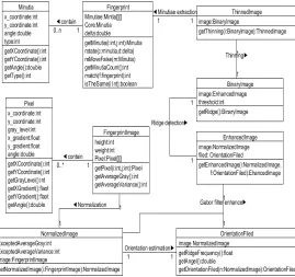
2.4.1 Class design
Figure 2.7 Main class design diagram
This is the main class design diagram, some class maybe not consider in it, some class elements probably will be changed in coding.
2.4.2 Programming design
The idea of this design document is to separate this system into several modules, and analysis how to implement each module. This part is to design procedural of each module, in order to show the flow control of each module. Note that the pseudo code of this part only shows the logical organized of each module. Pseudo code will not show the algorithm in detail.
1.Main application Pseudo code
Begin
Input fingerprint
Fingerprint pre-processing
If enroll
Add fingerprint to database
If match in database
Select fingerprint in database.
If match with another fingerprint
Input fingerprint_2
Fingerprint_2 pre-processing
Match fingerprint with fingerprint_2
End
2.Image pre-processing module Pseudo code
Begin
Input image
Image normalization
Image orientation estimation
Image enhancement
Image ridge detection
Image thinning
Minutia extraction
End
Pseudo code of normalization
Begin
Input image
Get average gray value from image
Get average variance from image
Get each pixel’s gray value in image
Calculate each pixel’s normalization value
Set each pixel’s gray value become the normalized value
Return normalized image
End
Pseudo code of orientation estimation
Begin
Input normalized image
Calculate each pixel’s gradient in x axis
Calculate each pixel’s gradient in y axis
Divide image into some block b
B.size() = 16*16 // 16 pixel * 16 pixel
For all block b in image
For all pixel p in block b
Calculate the sum of all pixel’s gradient in x axis
Calculate b’s orientation base on sum of all pixel’s gradient in x axis and
Sum of all pixel’s gradient in x axis
Return orientation filed
End
Pseudo code of image enhancement
Begin
Input normalized image
Input orientation file
F = ridge frequency // base on orientation file
A = ridge angle direction// base on orientation file
Calculate the new pixel gray value in normalized image
Set the new gray value in normalized image
Return enhanced image
End
Pseudo code of ridge detection
Begin
Input enhanced image
Calculate a gray level threshold
I = get pixel gray value in image
If I > gray level threshold
Set pixel gray value is 1
Else
Set pixel gray value is 0
Return image
End
Pseudo code of thinning
Begin
Input image
Thinning image using Zhang-Suen Thinning algorithm
Return thinned image
End
Pseudo code of minutiae extraction
Begin
Count = 0
Calculate the value change of each pixel p and its 8 neighbors
Begin
If 1 change to 0
Count ++
If 0 change to 1
Count ++
End
If count = 6
P is a bifurcation
If count = 2
P is a ridge ending
End
3.Image recognition module Pseudo code
Begin
Input pre-processing image_1
Input pre-processing image_2
Find core and delta in image_1
Rotate image_1 and image_2 base on their core and delta angle
Match minutiae in image_1 and image_2
If same minutiae >= 12
Return true
Else
Return false
End
1. 4. Database management Pseudo code
Pseudo code of enroll
Begin
Input image
If image is after pre-processing
Enroll
Else
Go to pre-processing
End
Pseudo code of math fingerprint in database
Begin
Input image
If image is after pre-processing
Rotate image
Math minutiae in image to database
Return result
Else
Go to pre-processing
End
2.
Conclusion
In this paper, we implement finger print recognition scheme with multilayer neural network and minutia method for the feature extraction. This approach we extracted 80 features of every image using ridge scheme of minutia method of feature extraction and multilayer neural network for the classification and recognition of finger print. In this paper we describe how to implement each functional which we explained in functional specification. This design is in high level software design, it includes architectural design, data design interface design and procedural design.
References:
[1] L. Hong, Y. Wan, and A. K. Jain, “Fingerprint image enhancement: Algorithms and performance evaluation”, IEEE Transactions on Pattern Analysis and Machine Intelligence, vol. 20(8), 1988, pp. 777–789.
[2] M. K. Khan, “Fingerprint Biometric-based Self Authentication and Deniable Authentication Schemes for the Electronic World”, IETE Technical Review, Volume 26, Issue 3, 2009. [3] A. K. Jain, L. Hong, and R. Bolle, “On-line fingerprint verification”, IEEE Transactions on Pattern Analysis and Machine Intelligence, 19(4), 1997, pp. 302–314.
[4] A. K. Jain, L. Hong, S. Pankanti, and R. Bolle, “ An identity authentication system using fingerprints”. Proc. IEEE, 85(9), 1997, pp.1365– 1388.
[5] A. K. Jain, S. Prabhakar, L. Hong, and S. Pankanti, “Filterbank-based fingerprint matching”, Image Processing, IEEE Transactions on, 9(5), 2000, pp. 846–859.
[6] M. Kaur, M. Singh, P.S. Sandhu, “Fingerprint Verification system using Minutiae Verification Technique”, Proceedings of world Academy of Science, Engineering and Technology, vol. 36, 2008.
Science Issues, vol. 7, issue 3, no. 7, 2010, pp. 11-16.
[8] R. Cappelli, A. Lumini, D. Maio, and D. Maltoni, “Fingerprint classification by directional image partitioning”, Pattern Analysis and Machine Intelligence, IEEE Transactions on, 21(5), 2002, pp. 402–421.
[9] R. Cappelli, D. Maio, J. L. Wayman, and A. K. Jain, “Performance evaluation of fingerprint verification systems. IEEE Transactions on Pattern Analysis and Machine Intelligence”, 28(1), 2006, pp. 3–18.
[10] S. Pankanti, S. Prabhakar, and A. K. Jain, “On the individuality of fingerprints”, IEEE Transactions on Pattern Analysis and Machine Intelligence, 24(8), 2002, pp. 1010–1025.
[11] A. K. Jain, F. Patrick, A. Arun, “Handbook of Biometrics. Springer science and Business media”, I edition, 2008 pp. 1-42.