2
4. LOAD TORQUE CALCULATION
The load torque is obtained by following formula, Load Torque,
TL= (F1-F2)*(Diameter of Drum/2) (1)
In the present work a load of 5Kg is applied at the end ’A’ of load drum. Find out the tensions produced in the band due to this load, and it can be obtained as under.
T2= 8.1 N and T1=28.86 N, if diameter of drum=90 mm, where T1= Tight side tension, T2= Slack side tension, µ= Coefficient of friction between band and the drum. Then, the load torques applied at drum shaft S2 is TL=934 N-mm.
5. SHAFT DESIGN
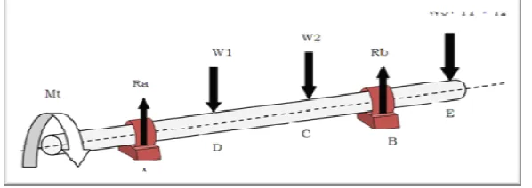
The In Figure 3, let Ra and Rb be the reactions developed at bearings B1 and B2 due to rotors C, D and load drum. The force acting at the end E is combined effect of weight of load drum and tension induced in the belt due to applied load. So, the force at E is likely to change with the change in applied load. The detailed procedure is systematically elaborated in following article.
load torque.
5.1. Design torque
KL = 2.2, Power = .5 hp, Speed = 1440 rpm
Td = 5.28 Nm
5.2. Calculation of bending moment
Force at E = W + T1 + T2
= 200 + 144.33 + 40.88
= 385.21 N
∑Fv = 0
Ra + Rb = 785.21
∑MA = 0
Rb =(200x80+200x160+ 385.21x300)/240 Rb = 681.51 N
Ra = 103.69 N MA = MB = 0
MB = -385.21 * 60 = -23.11 Nm
MD =-385.21 * 140 + 681.51* 80
= 0.591 Nm
MC = -385.21*220+681.51*160-200*80
= 8.2 Nm
Fig. 2. Schematic diagram of load drum
3
Selecting maximum bending moment at B, MB = 23.11 Nm
5.3. Maximum stress, τmax
Syt= 296 MPa,
Factor of safety, f.s = 2 Kb = 3 and Kt= 3
Torsional moment, Mt = 5.28 Nm Bending moment, MB = 5.214 Nm
d = 17.8 mm
Selecting standard diameter, d = 25 mm
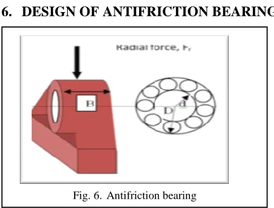
6. DESIGN OF ANTIFRICTION BEARING
There are two antifriction bearings B1 and B2 used in the experimental setup. The maximum reaction developed at bearing B2 i.e. Rb = 681.63 N is considered for designing the bearing.
6.1. Equivalent load coming on bearing, Fe, N
Fe = (XFr+ YFa) KsKoKpKr
Fr= 681.5 N
Fa= 0 N
e = Fa/ Fr
e = 0
Selecting self aligning ball bearing X = 1, Y = 2.3
Ko = 1 (constant rotational speed) Kp = 1 (no preloaded bearing)
Kr = 1(outer race fixed inner race rotating). Ks = 2 (moderate shock load)
Fe = (XFr+ YFa) KsKoKpKr
= (1x 681.5 + 0) x 1 x 1 x 1 x 2 = 1363 N
6.2. Life of bearing, L (million revolution)
L = (C/Fe) n Kret.
L = 500 (demonstration model) n = 3 for ball bearing
Kret = 1 (reliability = 90%) C =(500)(1/3) x Fe
C = 10818.138 N
Selecting series 02xx (C = 11000) Dimension d = 25 mm,
D = 52 mm, B = 15 mm.
Fig. 6.Antifriction bearing Fig. 4. FBD of shaft S2
4
7. DESIGN OF COUPLING
Number of jaws, n = 2 Shaft diameter, d = 25 mm a = (1.8 – 2.5) x d
= 2.1 x 25 = 52.5 mm b = (1.5 – 2.1) x d = 1.8 X 25 = 45 mm
h = (0.3d + 12.5) = 20 mm
8. OPERATION OF EXPERIMENTAL
SETUP
A load is being applied at the point A of a load drum thus it creates difference in the tensions of the band. This difference indeed provides the load torque on the drum shaft. On the other hand, an electrical energy is fed to motor which converts it into the mechanical energy. This mechanical energy is nothing but the driving power which is the product of driving torque and angular velocity of shaft. Thus, the driving power at 1440 rpm is getting transferred to the load drum shaft with the help of jaw coupling JC. This driving torque actually overcomes the load torque offered at the load drum.
9. CONCLUSION
The experimental setup has been developed for observing the behavior of coupling under misalignment condition. The vibration behavior two jaw coupling is noted under different loading condition at different speeds. In future the model could be used for testing different types of couplings by making some modifications.
REFERENCES
[1]. Shiwalkar B.D. “Design of Machine Elements”, 2nd Edition, Techno Publicaitons.
[2]. Shiwalkar B.D.“Design Data Book for Machine Elements” 1st Edition, Techno Publicaitons.
[3]. Khurmi R.S. “A Text Book of Machine Design”. [4]. Hariharan V. And Srinivasan P.S.S. “Vibrational Analysis of Flexible Coupling by Considering Unbalance” World Applied Sciences Journal 8 (8): 1022-1031, 2010I SSN 1818-4952.
[5]. Hariharan V. and Srinivasan PSS. “Vibration analysis of misaligned shaft –ball bearing system”. Vol.2 no. 9 (Sep 2009) ISSN: 0974- 6846.
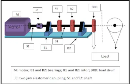
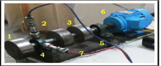
1. Load drum (BRD); 2. Rotor (R1); 3. Rotor (R3); 4. Bearing (B2); 5. Bearing (B1); 6. Motor (M); 7. Shaft (S2)
5
[6]. Jackson, C., 1973, "Cold and Hot Alignment Techniques of Turbomachinery," Proc. 2nd Turbomachinery Symposium, Turbomachinery Laboratory, Texas A&M University, College Station, Texas, pp. 1-7.
7]. Mancuso, J., 1994, "General Purpose Vs Special Purpose Couplings," Proc. 23rdTurbomachinery Symposium, Turbomachinery Laboratory, Texas A&M University, College Station, Texas, pp. 167-177.
[8]. Mitchell John, "Introduction to machinary analyssi and monitering" 2nd Edition, Pennwell Books Publication, Tulsa, Oklahoma, 1993.
[9]. Piotrowski, J., “Shaft Alignment Hand-book, Marcel Dekker Inc, 1995”.
10]. Rao S.S, “Mechanical Vibrations” 4th edition, Pearson Education, Inc. and Dorling Kindersley Publication, page no. 31-37.
[11]. Schenck H. Jr., "Theories of Engineering experimentation" 1st Edition, McgrawHill, Inc. 1967. [12]. Sekhar, A.S., and Prabhu, B.S., “Effect of Coupling Misalignment on Vibrations of Rotating Machinery,” Journal of Sound and Vibration, Vol. 185(4), 1995, pp.655-671.
[13]. Sinhaa.J.K. Leesb.A.W. , Friswellc.M.I. , “Estimating unbalance and misalignment of a flexible rotating machine from a single run-down”. Journal of Sound and Vibration 272 (2004) 967–989.