PERFORMANCE EVALUATION OF RMD
(RESOURCE MANAGEMENT IN DIFFSERV)
WITHIN NSIS (NEXT STEPS IN SIGNALING)
Master of Science Thesis
By Desislava C. Dimitrova
Committee: Date:
Dr. ir. G. Karagiannis1(first supervisor) July 6, 2006 Prof. dr. Hans van den Berg1,2
Dr. ir. P. T. de Boer1
1 University of Twente, Faculty Electrical Engineering, Mathematics & Computer Science, Chair Design and Analysis of Communication Systems, Enschede, The Netherlands
A new signaling framework is developed by the NSIS (Next Steps In Signaling) working group within IETF. One of the purposes of this framework is to support quality of service provisioning. A particular signaling protocol to deliver quality of service to end users is the RMD-QOSM protocol of the NSIS framework.
The main goal of this research is to evaluate the performance behavior of the RMD-QOSM protocol in a realistically simulated network. A simulation model within the Network Simulator (ns) version 2.29 is developed. The model includes traffic generation, the RMD-QOSM protocol behavior, and the transmission media.
The RMD-QOSM performance is tested by using VoIP simulated flows with three priorities – low, medium and high.
In the first set of experiments the impact of dropping marked bytes on the severe congestion detection and handling solution is observed when multiple severe congestion points are occurring. In the second set of experiments the effect of using an ingress-egress pair aggregate on the severe congestion performance is observed. In both experiments unidirectional flows are considered when the flows pass through different ingresses but the same egress.
In the next three sets of experiments bi-directional reservations are considered. In the third set is observed the influence of the reservation sizes of the forward and reverse directions on severe congestion situations on either the forward or the reverse path. The fourth set tests how flow termination, based on reservation sizes, affects the performance of the severe congestion solutions. In the fifth set of experiments the impact of flow termination, based on the severe congestion state of the ingress, on the performance of the severe congestion solutions on the forward and on the reverse direction is observed.
The last set of experiments concentrates on the state scalability of the RMD-QOSM protocol when compared to the pure QoS NSLP protocol.
Samenvatting
De IETF werkgroep Next Steps In Signaling (NSIS) is verantwoordelijk voor de ontwikkeling van een nieuw raamwerk voor signaleren. Één van de doelen van dit raamwerk is om de kwaliteit van service in te schatten. Een signalerend protocol voor kwaliteit van service aan de eindgebruikers is het RMD-QOSM protocol dat deel uitmaakt van het NSIS raamwerk.
Het hoofddoel van dit onderzoek is de evaluatie van de prestaties van RMD-QOSM in een realistisch gesimuleerd netwerk. Naar aanleiding hiervan is voor de netwerksimulator (ns) een simulatiemodel ontwikkeld. Het model bevat een pakketgenerator, het RMD-QOSM protocol en een transmissie medium.
Voor het evalueren van de RMD-QOSM QoIP zijn netwerkstromen met drie prioriteiten gebruikt, namelijk: hoog, gemiddeld en laag.
In de eerste groep experimenten is het effect van gemarkeerde (‘drop’) gegevenspakketten en het oplossen van sterke congestie onderzocht, wanneer deze congestie plaatsvindt op meerdere verbindingen. De tweede groep van experimenten richt zich op het monitoren van het oplossen van sterke congestie als een complex ingress-egress paar gebruikt wordt.
In beide experimenten is aandacht besteed aan eenrichtingsstromen, die afkomstig zijn van verschillende ingress knooppunten, maar arriveren bij hetzelfde egress knooppunt.
In de volgende drie groepen experimenten zijn tweerichtingsreserveringen gebruikt. Het derde experiment beschouwt de invloed van de reserveringsgrootte van de beide richtingen aangaande het oplossen van sterke congestie, wanneer deze optreedt in één van de twee richtingen. Voor de vierde groep experimenten is een geoptimaliseerd mechanisme voor afbreking van de netwerkstroom toegepast. Het mechanisme maakt gebruik van de reserveringsgrootte. De prestatie bij sterke congestie is geëvalueerd. In de vijfde groep experimenten is het mechanisme voor het oplossen van sterke congestie geoptimaliseerd en zijn de prestaties bij tweerichtingsreserveringen geëvalueerd in de situatie met sterke congestie in beide richtingen.
Het laatste experiment betreft de schaalbaarheid van RMD-QOSM in vergelijking met het pure QoS NSLP protocol.
Door de eerste groep experimenten wordt duidelijk dat een daling van gemarkeerde gegevenspakketten de tijd voor het detecteren en oplossen van sterke congestie verlengd. De tweede groep experimenten bewijst dat bij toepassing van een ingress-egress paar het
Preface
Allow me to welcome everyone that is interested in this research. If the dear reader, after he/she has read the introduction and the discussions chapter, is still eager to continue to the depths of this report I have successfully accomplished the mission to bring out an appealing topic.
It is a fact that, during the last decade, new applications and services for fixed and mobile devices are developed at high rate. This requires the standardization of new network protocols to provide optimal operation for these novelties. One very important network aspect is service differentiation and quality of service provisioning. A new framework of protocols is being developed to answer the divers signaling needs, one of which is quality of service delivery. The protocol in question is called RMD-QOSM and the motive behind this research is the performance evaluation of this RMD-QOSM.
This research was conducted during my master thesis within the DACS group of the University of Twente, Enschede, The Netherlands, where I was lucky to do my Master program. My first supervisor, dr. ir. G. Karagiannis, is one of the designers of the new protocol and has helped me in understanding how it operates. Together with him goals of the research were set and finally successfully accomplished. Finally he has helped me a lot of feedback about the scientific look of the thesis. My other two supervisors, prof. dr. H. van den Berg and dr. ir. P.T. de Boer, have always answered my questions and have provided me support during the writing of this thesis.
The preparation and the realization of this research required a lot of dedication but fortunately also improved a lot of my capabilities. I have fought my way through programming in C++ and OTcl tutorials [ns1, www; ns2, www]. I got to know how to use the ns2, a simulation environment to test protocols, even with the help of the ns2 manual. Most importantly I have learned what it means to design a protocol and to create a simulation model for it. The hours of simulation have thought me never to underestimate the things that can go wrong.
Finally, I want to thank to all the people that have stand behind me during the master assignment. Beginning with my family, my mum and dad, Filip and Ruben, which have literally survived me. Thanks to Simon and Adrian, my second family. I bid my gratitude to Jan Schut, my study supervisor and my flat-mates and friends that actually believed I am capable of graduating. Special thanks to Gerjan Stokking and Andras Csaszar, which have helped me with the simulation model and the simulator.
DSCP DiffServ Code Point
GIST General Internet Signaling Transport IETF Internet Engineering Task Force
IP Internet Protocol
MBAC Measurement Based Admission Control MRI Message Routing Information
NSIS Next Steps In Signaling
NSLP NSIS Signaling Layer Protocol NTLP NSIS Transport Layer Protocol PDR Per Domain Reservation
PHB Per Hop Behavior
PHR Per Hop Reservation
QNE QoS NSIS Entity
QNI QoS NSIS Initiator
QNR QoS NSIS Responder
QoS Quality of Service
QOSM Quality Of Service Model QSPEC Quality
RII Request Identification Information RMD Reservation Management in DiffServ
RMD-QOSM Resource Management in DiffServ Quality Of Service Model RMF Resource Management Function
RODA RMD On DemAnd
Table of Contents
1.1 IntServ framework and RSVP protocol... 10
1.2 DiffServ framework... 11
1.3 The NSIS protocol framework ... 12
1.4 Goal and objectives of the assignment ... 13
1.5 Organization of the report... 14
2 Problem analysis... 15
3 NSIS framework signaling protocols ... 17
3.1 Introduction ... 17
3.2 Next Step In Signaling (NSIS) framework... 17
3.2.1 The NSIS protocol suite ... 17
3.2.2 The transport supportive layer GIST... 20
3.3 QoS NSLP protocol... 21
3.3.1 Objects and messages ... 22
3.3.2 Quality of service definition (QSPEC)... 24
3.3.3 Example of QoS-NSLP operation ... 25
3.4 RMD model within QoS NSLP... 26
3.4.1 RMD-QOSM QSPEC... 27
3.4.2 Admission control ... 29
3.4.3 Severe congestion... 30
3.5 RMD QoS NSLP Unidirectional Operation ... 31
3.5.1 Successful reservation procedure ... 32
3.5.2 Unsuccessful reservation procedure ... 32
3.5.3 Refresh procedure... 34
3.5.4 Release procedure... 34
3.5.5 Severe congestion procedure... 39
3.6 QoS NSLP Bidirectional Operation ... 39
3.6.1 Successful and unsuccessful reservation procedure ... 39
3.6.2 Refresh and release procedure... 40
3.6.3 Severe congestion procedure... 40
4 Base RMD simulation model ... 42
4.1 RMD protocol framework ... 42
4.1.1 Nodes... 43
4.1.2 Messages... 43
4.1.3 Header format... 44
4.2 RMD protocol mechanisms ... 45
4.2.1 Admission control mechanisms... 45
4.2.2 Severe congestion detection mechanism ... 46
4.2.3 Severe congestion solving mechanism... 47
4.3.2 Links... 49
4.3.3 States ... 49
4.3.4 Admission control ... 51
4.3.5 Severe congestion detection and solving ... 51
4.3.6 Monitor support... 52
4.3.7 Scenarios ... 52
4.4 Protocol – model conformance ... 56
4.4.1 Used methods to test conformance... 56
4.4.2 Ingress node... 57
4.4.3 Egress node ... 57
5 Comparison of base RMD simulation model and RMD QOSM ... 59
5.1 Grounds for comparison... 59
5.2 Comparativeanalysis ... 60
5.2.1 New functionality for QoS NSLP ... 60
5.2.2 Required modifications for the RMD-QOSM implementation... 61
5.2.3 Necessary extensions for the base simulation model ... 63
5.3 Conclusions ... 64
6 Simulation model design... 65
6.1 Used simulation model principles ... 65
6.2 Goals of the design... 66
6.3 Simulation model design... 67
6.4 RMD-QOSM module design ... 70
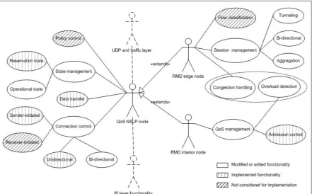
6.4.1 RMD-QOSM use case diagram... 70
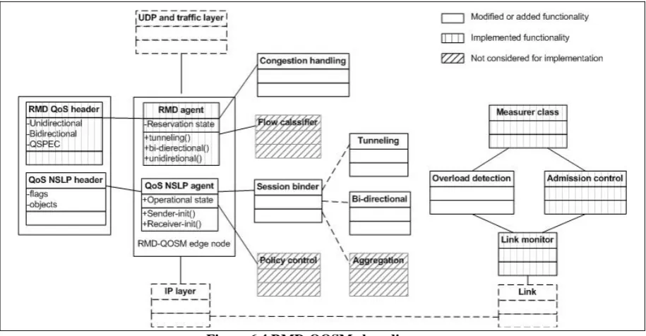
6.4.2 RMD-QOSM class diagram ... 73
6.4.3 Support software classes ... 76
6.5 Re-designing issues ... 76
6.5.1 Severe congestion detection and notification issues ... 77
6.5.2 Flow termination issues... 77
6.5.3 Severe congestion situation in bi-directional reservations issues ... 78
7 Model implementation in ns2 simulator... 80
7.1 Simulation model implementation ... 80
7.2 RMD-QOSM module implementation... 82
7.2.1 RMD-QOSM link objects ... 82
7.2.2 RMD-QOSM headers... 86
7.2.3 Node implementation ... 87
7.2.4 “Congestion handling” software class... 89
7.2.5 Session binder software class... 90
7.3 Support software classes ... 91
8 Simulation Experiments ... 92
8.1 Common settings... 93
8.1.1 Performance parameters... 93
8.1.2 Performance measures... 94
8.2 Experiment 1: Dropping marked packets... 94
8.2.1 Higher severe congestion level on the first link... 95
8.2.2 Higher severe congestion level on the second link ... 97
8.2.3 Average dropping probability calculated during “Higher congestion on the first link” scenario ... 100
8.4 Experiment 3: Sizes of bi-directional reservations in forward and reverse
direction... 105
8.4.1 Severe congestion on the forward path... 106
8.4.2 Severe congestion on the reverse path... 107
8.5 Experiment 4: Flow termination based on size: ... 111
8.6 Experiment 5: Optimization of the severe congestion mechanism ... 113
8.7 State scalability comparison RMD-QOSM vs. QoS NSLP... 114
9 Discussion... 118
9.1 Conclusions ... 118
9.2 Achieved goals ... 119
9.3 Contribution... 120
9.4 Future work ... 120
References ... 121
Appendices ... 124
Appendix A.1: RMD simulation model states ... 124
Appendix A.2: State machines ... 125
Appendix A.3: Source file documentation ... 127
Appendix B: Implementation functions ... 128
Appendix C.1: Two point severe congestion ... 133
Appendix C.2: Pair vs. no-pair aggregate ... 136
Appendix C.3: One path severe congestion... 137
Quality of Service (QoS) support in the Internet plays increasingly significant role. That is due to the combination of more available network capacity and high resource demands from real time services, such as voice over IP (VoIP). First of all why bother to provide quality of service on the Internet? Each application type has its own requirements towards the media characteristics, some cannot tolerate delay, whereas others cannot tolerate packet drop. Classification among the applications is needed which results in differentiation in the provided QoS. For example, if you want to play a multiplayer game, for instance World of War Craft, you can survive temporal change in the scenery but being dead and not knowing it can be quite annoying. In other words, you would like your application packets to arrive on time rather than without packet loss.
Soon a need arose to provide different treatment within one QoS category. To give an example when your house is on fire you would rather prefer to call the fire brigade than your parents. The former if classified as an emergency call and the latter as a domestic call, which can be assigned different priorities.
Quality of Service can be provided if a packet classification mechanism exists and a way to manage the network resources is provided. How the applications should be classified in QoS groups is described in QoS frameworks. The definition of how the network nodes are informed on the type of the supported application and on how the network resources should be managed is the task of the so called protocols for quality of service signaling and provisioning.
The first QoS framework that has been standardized by the IETF (Internet Engineering Task Force) is IntServ (Integrated Services) [RFC1633], which uses for QoS signaling support, the Resource Reservation Protocol (RSVP) [RFC2205]. Another QoS framework that has been standardized by the IETF is DiffServ (Differentiated Services) [RFC2475].
1.1 IntServ framework and RSVP protocol
RSVP is a protocol specified to mainly work with the IntServ QoS framework. Its main goal is to allow data flow initiators to inform network nodes, on the path of data flow (i.e., data path), about the QoS requirements of the flow. RSVP is used to make resource reservations (reservation state) only by the nodes that are located on the path followed by the user data. It is therefore, denoted as a path-coupled or path oriented reservation protocol. RSVP is a soft state protocol, which means that nodes have to initiate periodically refresh messages to keep the reservation state active. A reservation session can be released if it is not refreshed and the lifetime of the reservation state expires or by explicit release of the reserved resources.
In the IntServ/RSVP protocol data flows achieve quality of service by announcing their service requirements to the network nodes and making resource reservations. That is done on a per flows basis and unfortunately does not scale efficiently in the global Internet [BaKa05].
Introduction
• lack of fragmentation causing limited length of the transport units and lower link resource utilization;
• reliability problems due to the use of IP or UDP as transport layers, for the transport of the messages, instead of using e.g., TCP. The message delivery is assured only by retransmissions. This imposes constraints on the signaling;
• lack of support for network mobility, which is one of the biggest problems currently in the wireless and ad-hoc networks in particular;
• discovery and signaling message delivery are combined in one step which does not allow RSVP to make use of the available security solutions for Internet.
1.2 DiffServ framework
To support scalability in a more efficient way, a new QoS framework/architecture has been developed by the IETF, called Differentiated Services or DiffServ [RFC2475]. In DiffServ each flow is classified in one of fixed range traffic classes, which are identified by the Type of Service (ToS) field in the IPv4 protocol or by the traffic class field in the IPv6 protocol. These fields are denoted as DS fields. Each traffic class has predefined QoS parameters and all flows classified in the same class are called DS aggregate traffic. Every DS aggregated traffic receives the same level of quality of service, denoted as a Per Hop Behavior (PHB). Packets that are using the same PHB are marked with the same DS code point (DSCP), see below, and receive the same forwarding behavior. DiffServ is scalable for core networks because it provides QoS to DS aggregated traffic, instead of providing QoS to each individual flow.
The DiffServ terminology used in this report is listed below, see also [RFC2475].
DS edge node – a DS node that connects one DS domain to a node either in another DS
domain or in a domain that is not DS-capable.
DS-capable – capable of implementing differentiated services as described in this
architecture; usually used in reference to a domain consisting of DS-compliant nodes.
DS code point – a specific value of the DSCP portion of the DS field, used to select a PHB. DS domain – a DS-capable domain; a contiguous set of nodes which operate with a
common set of service provisioning policies and PHB definitions.
DS egress node – a DS boundary node in its role in handling traffic as it leaves a DS
domain.
DS ingress node – a DS boundary node in its role in handling traffic as it enters a DS
domain.
DS interior node – a DS node that is not a DS boundary node.
DS field – the IPv4 header TOS octet or the IPv6 Traffic Class octet. The bits of the DSCP
field encode the DS code point, while the remaining bits are currently unused.
Per-Hop-Behavior (PHB) – the externally observable forwarding behavior applied at a
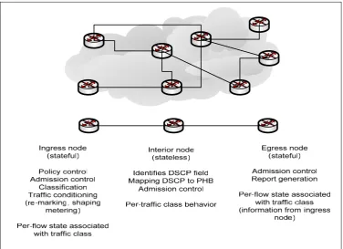
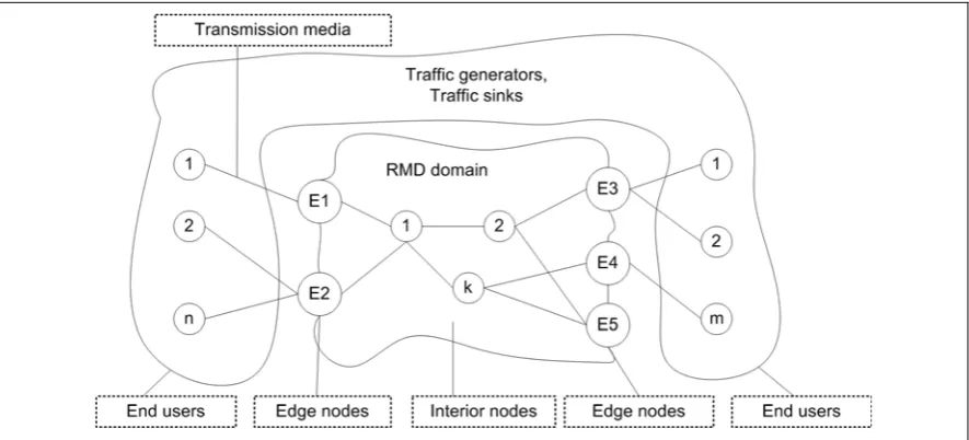
Figure 1.1 General overview of a DiffServ domain
The operation of a DiffServ domain is based on simple general principles and is presented in Figure 1.1. A flow enters the domain at the ingress node, where first admission control is applied. Second the flow is examined and classified in an aggregate behavior and it is given a DS code point (DSCP). To perform the classification a traffic classification policy is used. Subsequently, sometimes traffic conditioning might be needed. This includes shaping (if the flow generates more date that is allowed for its traffic class), metering (collecting data for the behavior of the flow), remarking and scheduling. Remarking may, for example, happen on the border of two domains when the first is non-DiffServ domain but the second is. Thus the edge nodes need not only maintain information of its own domain but also from the connected domains. Interior nodes need not have such knowledge since they only handle intra-domain traffic.
After the flow passes the ingress node, the user data packets associated with the flow, are forwarded via the DS interior nodes to the DS egress node. Each node, by checking the DSCP, can associate each user data packet with a predefined PHB. When the egress node receives a packet it can associate it with the original flow.
1.3 The NSIS protocol framework
Introduction
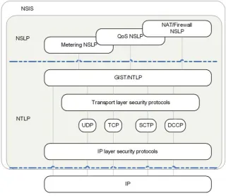
The lower layer, denoted as NSIS Transport Layer Protocol (NTLP), provides the transport support of the signaling application messages. The NTLP defines what information should be included in the NTLP layer header and which transport mechanisms are used, i.e. reliable, unreliable, should be used, etc. The NTLP carries the signaling application messages that are generated by the upper layer, i.e., NSIS Signaling Layer Protocol (NSLP). At this layer the rules of generation and processing of signaling messages are defined along with the description of the signaling messages header format. NSLP is meant to be a general signaling protocol, one of which purposes is to signal for QoS provisioning. This special case of NSLP, called QoS NSLP, is responsible for generation of signaling messages used to support the QoS signaling. The QoS signaling can be associated with information related to the used flow classification, the QoS requirements on e.g., delay, bandwidth, jitter, and the administrative permissions assigned to flows that request QoS, etc. The QoS NSLP signaling messages carry a QoS Specification (QSPEC) object, which is dedicated to the description of the QoS parameters.
The QoS NSLP can support several QoS frameworks. These QoS frameworks determine which QoS parameters are used, what their possible values are, how the network nodes should use the parameters and eventually how the network resources should be managed to provide the desired QoS level. Within NSIS the QoS frameworks are called QoS Models (QOSM).
In NSIS, the RMD-QOSM model represents the combination of the DiffServ QoS framework with the Resource Management in DiffServ (RMD), see chapter 4. The specifics on how the quality of service is signaled and provided are included in the RMD QSPEC.
To summarize, imagine a network where the nodes support the NSIS framework. After the signaling messages are processed at the lower network layers they arrive first at the NTLP layer. There, the NTLP header is processed and removed. The upper signaling application layer is recognized as QoS NSLP and the resulting message is passed to it. At the QoS NSLP layer the QoS NSLP header is processed and removed. One part of it is the (RMD) QSPEC, which tells the QoS NSLP layer that RMD-QOSM is used. The RMD QSPEC is passed to the RMD-QOSM for processing after which the node knows how to reserve network resources. This is done is every RMD-QOSM aware node.
1.4 Goal and objectives of the assignment
Project goal: The main goal of this assignment is to accomplish the performance
evaluation of the main severe congestion mechanisms used in the RMD-QOSM by using simulation experiments.
In order to satisfy the main goal of the assignment several objectives have been identified:
• Study of the protocol specifications of QoS NSLP, QSPEC and RMD-QOSM.
• Study available simulation models on the topic.
• Design of a simulation model that can be used for performance evaluation of RMD-QOSM.
• Implementation of the simulation model in the Network Simulator (ns) environment.
• Define and perform experiments to evaluate the performance of RMD-QOSM.
• Analyze the experiment results, draw conclusions and provide feedback.
1.5 Organization of the report
2 Problem analysis
A simulation model that is to be used for performance evaluation should include the functionality of the tested protocol along with functionalities supported by the network topology, where the protocol is to be evaluated. The implementation of the evaluated protocol, when used for performance analysis, should represent closely the protocol specifications without having to include details that are not relevant to the performance or have supportive role. Some simplifications, assumptions and abstractions can be done. When the protocol has a complex nature it has to be determined which mechanism should be included and which can be ignored.
RMD-QOSM is such protocol. It consists of several mechanisms, which in co-operation deliver the end protocol behavior. Major mechanisms are the algorithms for admission control, severe congestion detection and handling and quality of service provisioning. Others have supportive role, such as mechanisms for authentication and authorization, flow classification to predefined level of service, security issues, etc. What is even more important is that RMD-QOSM is a combined product of a general signaling protocol, QoS NSLP, and a specific QOSM, see Chapter 1. To get familiar with the protocol behavior one has to study the specifications [NSLP] and [QSPEC], which cover the general processing rules at the QoS NSLP layer, and the [RMD NSLP] specification that concentrates on the specifics of the used QOSM.
RMD-QOSM uses the idea of Resource Management in DiffServ (RMD) [WeJa03] to deliver the required quality of service. The way of how resources are reserved and the mechanisms for admission control and severe congestion are applied in RMD are very similar if not identical as for RMD-QOSM. A simulation model of RMD already exists, which has been developed by András Császár and Atilla Tákacs from Ericsson Hungary [Ericsson, www] and is implemented in the network simulator (ns) environment [ns, www]. This RMD simulation model implements several possibilities for admission control, severe congestion detection and handling procedures and reservation methods to support quality of service provisioning. The mechanisms are described in diversity of papers with the above mentioned as authors [CsTa04, CsTa04]. The model was extended by Gerjan Stokkink to implement the use of DSCP and preemption priorities within the same DSCP class.
Due to the similarities in the behaviors of RMD and RMD-QOSM, the simulation model that can be used for RMD-QOSM could partly use the existing RMD simulation model. Before that, a comparison should be done, to determine which parts of the existing simulation model could be re-used and which modifications would be necessary.
To determine what functionality should be included in the RMD-QOSM simulation model it should be clear what part of the behavior will be evaluated. The goal formulated in chapter 1 is broad and is therefore divided in sub-goals. Their number is limited due to the broad functionality of RMD-QOSM and the little available time for research. The chosen sub-goals are listed below:
• Performance evaluation of severe congestion situations in unidirectional operation. Several experiments on the topic were already done but there are still unexamined aspects, e.g., severe congestion on two consecutive links. This point of the research aims at finding optimization solutions to the existing mechanisms.
• Performance evaluation of severe congestion in bi-directional reservations. Experiments on the severe congestion occurrence only in one direction or in both are to be performed. As result of this sub-goal, a feedback to the specification about the bi-directional operations and possible optimizations of the algorithms, are expected.
• Performance evaluation of the admission control mechanism. A new approach towards the admission control mechanism is taken to support preemption priorities. It should be included in the simulation model of RMD-QOSM and be tested with simulated real flows generation.
• Performance evaluation in the means of protocol scalability. The RMD-QOSM protocol can be evaluated as a whole, and one of the aspects is how scalable it is. A research on that topic is provided without being exhaustive. The research is narrowed to the comparison between RMD-QOSM and the general QoS NSLP protocol.
3 NSIS framework signaling protocols
3.1 Introduction
In chapter 1 the need for quality of service provisioning in current IP based networks was discussed along with the need of new signaling protocol solution that will allow quality of service to be supported. As response to this need the NSIS working group of IETF [NSIS, www] is currently busy on developing a signaling protocol suite to support a variety of signaling applications.
NSIS stands for Next Steps In Signaling and this chapter presents a general description of the solution provided by the IETF working group in section 3.2 together with a short introduction of the first transport layer. Subsequently the second signaling layer of NSIS is reviewed in section 3.3 and detailed explanation of the particular protocol of interest is given in section 3.4. Section 3.5 is dedicated to the unidirectional operation of the protocol while section 3.6 concentrates on the bi-directional scenarios.
This chapter is based on the QoS NSLP protocol specification version 9, QSPEC specification version 8 and the RMD QoS NSLP, i.e., RMD-QOSM, protocol specification version 5. All additional changes introduced in newer versions of the specifications are not considered in this research assignment.
3.2 Next Step In Signaling (NSIS) framework
3.2.1 The NSIS protocol suite
The new protocol suite developed by NSIS is split into two protocol layers. The first, lower layer, i.e., NTLP, is responsible for the transport of the signaling messages and the second, upper layer, i.e., NSLP, is responsible for the generation of signaling messages with a predefined format and according to strict rules [BaKa05, KaBa04]. NTLP may use different transport and security protocols and it can operate in two modes – connection orientated (or reliable) and datagram (or unreliable) mode. Which transportation mode is to be used depends on the type of requested connection and on the information passed by the NSLP. NSLP supports the general features of a signaling protocol but each concrete NSLP realization is dependant on the signaling application to be served. The format and semantics of the messages used by different signaling applications are application specific. For example, messages used for quality of service signaling can be processed only by the nodes that support the signaling application for delivering quality of service.
Figure 3.1 NSIS architecture
The most distinguishable features of the NSIS protocol suite, see [FuBa05], are described below:
Transport of signaling messages: The separation of the protocol suite into two layers
makes the transportation of the signaling messages independent from their generation at the signaling application. In other words the upper layer is responsible for the creation of the messages and gives them signaling application specific meaning, while the lower layer only transports them throughout the NSIS aware nodes. This separation of duties allows on one hand different signaling application implementations to be developed and on the other hand different transport modes to be used.
Reservation model. The initiator of the reservation can be the sender or the receiver of the
data path, which makes NSIS more flexible. In NSIS it is as well possible nodes different from sender or receiver of the data path to initiate messages. Therefore not only end-to-end communication is supported but also edge-to-edge and edge-to-end.
As a soft state protocol NSIS nodes keep states that have a certain lifetime. When the
lifetime expires the state is no longer kept. To ensure that the node will process a session identified by a particular state the state has to be refreshed every predefined period of time. As result all nodes on the path will keep the particular state and the session will not be interrupted.
Scoping (or range) of signaling. The scoping (or range) of the signaling messages
NSIS framework signaling protocols
Table 3-1 Comparison between RSVP and NSIS
RSVP NSIS
Protocol structure Single layer Two layers
Transport IP or UDP Reliable, datagram
Reservation initiator Receiver Sender or receiver States Soft, explicit release Soft, explicit release QoS models IntServ, DiffServ IntServ Diffserv, other
Scope of signaling End-to-end End-to-end, host-to-edge, edge-too-edge
Multicast Yes No
NSIS does not support multicasting, which simplifies the functionality that have to be
supported by each NSIS aware node.
Bi-directional reservations are supported by the NSIS suite as the bound reservations
initiated and maintained simultaneously in the forward and reverse direction between a QNI (QoS NSLP Initiator) and a QNR (QoS NSLP Receiver).
A binding mechanism allows, for example, the identifiers of the two directions to be
related and therefore a stateful node knows which forward session to which reverse session corresponds.
Mobility support. NSIS uses for the identification of a flow, a Session ID, instead of using
the flow ID used by RSVP. Note that the flow ID is a set of five parameters, i.e.,: IP address of sender, IP address of receiver, port number of sender, port number of receiver and protocol ID. When a user is roaming, the flow ID changes, while the Session ID remains the same. This means that when the reservations are associated with Session IDs, the reservations that were initiated and maintained before roaming will also be kept after roaming.
Along with all above the NSIS protocol suite aims at high security level by implementing
security mechanisms in the suite itself or by using available security protocols. Separation of node discovery and transport of signaling messages opens a possibility to use different
security protocols. Therefore, NSIS can make use of already existing well tested security protocols.
The characteristics of NSIS are listed in Table 3-1 along with their presence or absence in the RSVP protocol [FuBa05]. The latter allows for a fast comparison and the advantages of the NSIS suite are easily recognized.
nodes IP address. In fact one session ID can be associated with one or more flow identifiers. As result NSIS supports node mobility, tunneling/bypassing and multi-homing [FuBa05].
3.2.2 The transport supportive layer GIST
The lower layer in the NSIS architecture defines a common protocol that all kind of signaling applications can use. Application specific functionality is given by the signaling protocols that form the upper NSIS layer. The main protocol used by NTLP to provide the transport of signaling messages is the General Internet Signaling Transport (GIST). GIST must be present if an upper layer NSIS protocol needs to be supported by a node. If some node on the sender-receiver path is not GIST enabled, then all NSIS messages are considered to be ordinarily data packets. The GIST terminology used in this report can be found in [ScHa06] and is given below:
Data flow: A set of packets identified by some fixed combination of header fields. Flows
are unidirectional (a bidirectional communication is considered a pair of unidirectional flows).
Session: A single application layer flow of information for which some state information is
to be manipulated or monitored. It is identified with a Session ID (SID) parameter
Sender: The node in the network which is the source of the packets in a flow. Could be a
host, or a router (e.g. if the flow is actually an aggregate).
Receiver: The node in the network which is the sink for the packets in a flow. Downstream: In the same direction as the data flow.
Upstream: In the opposite direction to the data flow.
Adjacent peer: The next node along the data path, in the upstream or downstream direction,
with which a GIST node explicitly interacts. The GIST peer discovery mechanisms implicitly determine whether two nodes will be adjacent.
GIST has two major goals – one to provide routing and second, transportation of signaling messages. The routing determines how to reach the adjacent peer along the data path, and
can be done independently for each direction of the connection. Two NTLP states are used for the routing – a routing state, used in the forwarding of the messages, and a message association state, used to relate incoming messages to a particular saved session. A
Message Association is a connection between two explicitly identified GIST adjacent peers
and a message, arriving from the signaling application, is connected to an established message association via the SID parameter of the message header.
Transportation is the delivery of signaling information from peer to peer [ScHa06]. The
signaling message delivery is divided in two transport modes, the Datagram Mode (D-mode) and the Connection Mode (C-(D-mode). The Datagram Mode (D-mode) sends GIST
messages between nodes without using any transport layer state or security protection and uses UDP encapsulation [ScHa06]. The connection Mode (C-mode), on other hand, sends
NSIS framework signaling protocols
communicate vie the interface, or API, defined between them. The primitives passed at the interface are of three groups – reliability or what transportation mode is desired; security or what security mode is required; and local processing or what special processing has to be done like prioritization, etc.
The messages generated at the GIST layer are see [ScHa06]:
• GIST-Query messages are used in the first phase of the discovery procedure, 3-way
handshake. It is always sent in datagram mode and leads to creation of routing state for the flow and also message association state if necessary.
• GIST-Response message is used in the second phase of the handshake and can be sent
in datagram or connection mode. If a message association is needed but it is not created this is accomplished during this phase.
• GIST-Confirm message is the last phase of the discovery procedure an also can be in
datagram or connection mode. If connection mode is used a message association must be established during the transfer of the previous two message types.
• GIST-Data message is used to encapsulate all messages coming from the NSLP layer. • GIST-Error message reports errors occurring at the GIST level.
• GIST-MA Hello message is used to keep a message association state.
For complete description of each message, see [ScHa06].
When a connection is to be established first the GIST discovery procedure is started. The procedure is between two peers and uses the GIST messages Query, Response and Confirm. As result the peers on the data path sender – receiver are discovered. Subsequently the signaling NSLP messages and the data are encapsulated in GIST Data messages. The GIST discovery procedure can be combined with the NSLP signalization to establish connection.
3.3 QoS NSLP protocol
The signaling layer protocol is tightly connected with the user applications in the end nodes. The tasks of NSLP are two – to create signaling application specific messages with well defined format and to give instructions how these messages are to be handled in the nodes. It was already mentioned that three signaling applications – NAT/firewall NSLP, metering NSLP and Quality of Service NSLP, are developed. The further discussion is concentrated in QoS NSLP.
QoS NSLP dictates the general common processing [MaKa06] of the signaling messages for quality of service provisioning. Different quality of service models (QOSM) can be used. The Resource Management Function (RMF) is responsible for processing specific
information for a particular QOSM. A special object within the QoS NSLP message, QSPEC, carries information on the quality of service parameters used by the different QOSM. QoS Model (QOSM) is the collective quality of service parameters and RMF
iven below:
NE: an NSIS Entity (NE), which supports the QoS NSLP.
rvation request for a session.
rvation state: State used/kept by Resource Management Function to describe
ded in the Message Routing Information (MRI) in GIST
operation state: State used/kept by QoS NSLP processing to handle messaging
3.3.1 Objects and messages
oS NSLP as each has a common header and a body.
tionobjects: are common for all quality of service models that can be used
information over resource
thentication and authorization of the
on the message type and the possible flags to be
sh, modify quality of service policy is tunneling where the initiator message travels to the end of the domain unprocessed and an additional local message is constructed.
The terminology used in this chapter is specified in [MaKa06] and is g
Q
QNI: the first node in the sequence of QNEs that issues a rese
QNR: the last node in the sequence of QNEs that receives a reservation request for a
session.
QoS rese
reserved resources for a session.
Flow ID: This is essentially inclu
for path-coupled signaling. Note that QoS-NSLP, currently, supports only path-coupled signaling.
QoS NSLP
aspects. It includes non-persistent and persistent state. The non-persistent state keeps information only during the processing of a message of the session. The persistent state is active during the whole existence of the session and is organized as a table [MaKa06].
Four message types are specified for Q
The body consists of three groups of message objects, which according to the specification [MaKa06] are:
Control informa
on top of QoS NSLP. The objects semantics and processing are standardized by the QoS NSLP functionality. The objects are presented in Table 3-2.
QoS specification object: carries the QOSM specific
management and includes the parameters to describe the requested quality of service. The QSPEC object is described in detail in section 3.3.
The content of a Policy object is used in the au
initiator (QNI). The policy control is performed by separate functionality, usually at the boundaries of an administrative domain.
The common header provides information
set. It precedes all other QoS NSLP objects and its format is given in Table 3-3. The RESERVE message is the only message that can manipulate – create, refre
NSIS framework signaling protocols
able 3-2 Control information objects
on
T
Type Descripti
Request Identification nique per-session number that is used every time a Information (RII)
A random, u
response is desired. The response has to come from the destination, thus it is different form the A flag (see Table 3-3) and has end-to-end importance. It is used to connect a Response for to a Reserve or Query.
Reservation Sequence between two peers that is increased
Number (RSN)
A random number, unique
every time a modify message is sent from the peer to the next one. It has local, peer-to-peer importance.
Refresh_period The period used by the node to generate refresh messages in the soft state operation mode.
Bound_session_ID Contains the Session Identifier (SID) of the session(s) that are bound with the current one. It is used in aggregations or when traversing a domain and using layering or tunneling.
Info_spec Organized in error classes and error codes which identify a occurrence of event, very often error.
Packet_clasifier Provides information on the Message Routing Method used and additional information in the form of flags.
ble 3-3 Common header
Description
Ta
Field Flag
RESERVE A message used for session initialization.
QUERY A message used for network resources check-up. RESPONSE A message used to respond back to previous request. Message
type
NOTIFY A message used to inform for special events.
Tear (T) An existing state (reservation and operation) must be terminated.
Reserve-init (R) A reverse initiation is required. Acknowledge
(A)
An explicit confirmation about the state installation is required.
Specific
Replace (R) carried in the message replaces the old one, which flags
The MRI
can be torn down. Used in rout changes. Generic
Scoping (S) the next hop and not
flags
The message is no be forwarded only to the whole path.
A QUERY message is generated for either receiver initiated reservation or if a node wants
The RESPONSE message carries the result of the Reserve or Query message processing on
the signaling path [MaKa06]. Only the Scoping flag can be set for a response message. The RSN/RII object relates the Reserve/Query message.
NOTIFY message is initiated asynchronous and is not dependant on previous message or
state processing. It is generated upon a network event, most frequently an error. This message has no specified flags [MaKa06].
3.3.2 Quality of service definition (QSPEC)
The Quality of service SPECification (QSPEC) is introduced to represent the quality of service model specifics in terms of message parameters and RMF handling [AsBa06]. The QSPEC is transparent for the QoS NSLP node functionality and is processed by the RMF. The resource management function should define processing scenarios for all QoS models that are currently implemented in the node.
The terminology specified in [AsBa06] and used in this chapter is given below:
QSPEC Control information is QOSM specific and it controls the way of how RMF should
process the QSPEC.
The QSPEC Description carries the desired by a flow quality of service, represented by
QSPEC objects.
A QSPEC Object is a cumulative building block used to represent quality of service level.
A QSPEC Object is identified by its Object ID and can be Control information, QoS Desired, QoS Available, QoS Reserved and Minimum QoS. QSPEC objects are generated by the initiator of the signaling session and can be:
• mandatory objects that must be present in the QSPEC and the receiver must be able
to interpret them;
• optional objects which can be included in the QSPEC and should be interpreted by
the receiver if present.
QSPEC Parameter is a formal way of describing the quality of service required by a used
application. One QSPEC Object can have many QSPEC Parameters. The QSPEC Parameter is identified by a Parameter ID and can be:
• a read-write parameter that can be changed by the RMF in every node on the
session path;
• a read-only parameter that cannot be modified by the intermediate nodes but only
by the initiator and the receiver node of the QSPEC.
Control information field gives general instructions to the resource management function
such as used QOSM, which procedure to process the QSPEC should be followed, etc. The QoS Description is a collective name of the four QSPEC objects with information on
NSIS framework signaling protocols
Table 3-4 QoS Desired object
Parameter Description Traffic
description
Information for the characteristics of the traffic given by the desired Bandwidth and the Token bucket. Desired in this case is equivalent to generated or the parameters values are taken from the initiator’s traffic. QoS Class Defines which class the initiator requires to be handled like. Three
parameters are possible. Which one is used and its value is QOSM specific. Priority Three types of priorities are defined and used to classifies the traffic within
the node and its manner of processing. Path latency
Path jitter Path BER
Optional parameter, which when available indicate the node should include then in the QoS Available object. They are used for path evaluation in the End node.
QoS Desired object transports the initiator request for quality of service. The parameters of
the object, see Table 3-4, are read-only and inform every node on the signaling path for the requested QoS.
The QoS Available object carries information about the available network resources that is
updated by the nodes on the signaling path. The parameters of this object are read-write. In the case of RESERVE or QUERY messages when the QoS Desired is evaluated the local node resources are checked. If they are less than the desired resources modification is done to the QoS Available object. In case of RESPONSE message the QoS Available object transports values of the available network resources.
A QoS Reserved object represents the actual resources, reserved on the data path and it has
as parameters traffic description, QoS class and priority.
The Minimum QoS object is defined by the initiator with read-only parameters. It gives the
lower boundary on the quality of service parameters, accepted by the initiator, and allows resource negotiation. This object is evaluated at the receiver and compared with the QoS Available object parameters. If the values of the available resources are below the values in the minimum QoS object parameters the connection cannot be established. If the Minimum QoS object is absent the end node will compare the desired and available objects and if the values of the available object are smaller than the ones of the desired object the connection procedure is aborted.
3.3.3 Example of QoS-NSLP operation
Figure 3.2 Sender initiated reservation
The initiator of the request (QNI) is the sender of the data flow. QNI generates a RESERVE message with the initiator QSPEC. At each intermediate QoS NSLP aware node first authentication and policy control are performed. Second, the control information is processed and the QSPEC is sent to the RMF. The RMF performs the resource check-up and if the reservation is admitted, a reservation and an operational state are installed and the RESERVE message is sent to the next peer. If any of the nodes do not have sufficient available resources, then no states are installed and a RESPONSE message is returned right away to the initiator. When the receiver (QNR) gets RESERVE message if the RII object is included a RESPONSE is initiated. QNR also installs states if the requested resources are free.
3.4 RMD model within QoS NSLP
The RMD QOSM is used when a QoS NSLP message has to traverse a RMD domain. It this case tunneling/bypassing is used and the original RESERVE message is sent unchanged to the egress node while a local RESERVE message is used to make the reservation within the domain. These local messages comply with the format of QoS NSLP messages as presented below. The message objects are as explained in section 3.3.1.
NSIS framework signaling protocols
Figure 3.3 RESERVE message format
Figure 3.4 QUERY message format
Figure 3.5 RESPONSE message format
Figure 3.6 NOTIFY message format
3.4.1 RMD-QOSM QSPEC
In the case of RMD-QOSM framework the used model is the Resource Management in DiffServ. In order to reflect the RMD quality of service provisioning the QSPEC consists of three objects: QoS Description, PHR container and PDR container [WeCs02]. The combination of them determines what quality of service is required by the application. Each one of the objects is described below.
3.4.1.1
QoS Description
Only one of the defined in section 3.3.2 objects is included in the QoS Description, carried by a RESERVE message, and that is the QoS Desired object, with two parameters Bandwidth and PHB class. Note that a RESPONSE message carries a QoS Reserved object. The Bandwidth parameter, with ID 3, signals how much resource would be needed by the flow and its format is presented in Figure 3.7. The PHB class parameter, with ID 7, currently carries information of the DSCP value of the flow. The DSCP value is used in the routers to distinguish between different traffic classes. The parameter format is presented in Figure 3.8.
Figure 3.7 Bandwidth parameter format
3.4.1.2
Per-hop reservation (PHR) container
The Per-Hop Reservation (PHR) container supports the resource reservation procedure and is processed by all nodes on the flow path. Its format in presented in Figure 3.9 and its parameters are described in Table 3-5
Figure 3.9 PHR container format
3.4.1.3
Per-domain reservation (PDR) container
The Per-Domain Reservation (PDR) container provides additional support to the PHB container for the connection establishment. The PDR container is in the base of the end-to-end communication. It also passes all nodes but is processed only by the edge nodes. Its format is presented on Figure 3.10 and the description of its fields in Table 3-6.
Figure 3.10 PDR container format
Table 3-5 PHR container fields
Parameters Description
Flags Flags for service use to support parameter handling. Container ID
1 2 3
PHR_RESOURCE_REQUEST Used for resource reservation PHR_REFRESH_UPDATE Used for resource refresh PHR_RELEASE_REQUEST Used for resource release Reserved Bits reserved for future use.
Length The length of the parameter in bytes.
S Indicates severe congestion occurrence. 0 for no congestion, 1 for congestion.
M Indicates node possibility to reserve resources. If 1 insufficient resources. Admitted
hops
Counts the number of nodes in which the reservation was successful. Set to 0 in the ingress node.
B If set bi-directional reservation is requested.
U (Hop_U) If set indicates the admitted hops counts must not be increased (in case of unsuccessful reservation).
Overload % Indicates the level of overload detected. Every node checks its own level and if necessary updates it.
NSIS framework signaling protocols
Table 3-6 PDR container fields
Parameters Description
Flags Flags for service use to support parameter handling. Container ID
PDR_RESERVATION_REQUEST Used for resource reservation PDR_REFRESH_REQUEST Used for resource refresh PDR_RELEASE_REQUEST Used for resource release PDR_RESERVATION_REPORT Result of reservation procedure PDR_REFRESH_REPORT Result of refresh procedure PDR_RELEASE_REPORT Result of release procedure PDR_CONGESTION_REPORT Indicates severe congestion Reserved Bits reserved for future use
Length The length of the parameter in bytes.
S Indicates severe congestion occurrence. 0 for no congestion, 1 for congestion.
M Indicates node possibility to reserve resources. If 1 insufficient resources.
Max admitted hops
Counts the number of nodes where the reservation was successful. Set to 0 in the ingress node.
B If set bi-directional reservation is in place.
Overload % Indicates the level of overload detected. Every node checks its own level and if necessary updates it.
Empty All zero bits. PDR Reverse
Requested Resources
Indicated the resources needed for the reverse direction in case of bi-directional reservation.
3.4.2 Admission control
Under the term admission control are united procedures that specify how network resources can be checked, when a reservation can be made and when it should be rejected. Within RMD-QOSM two types of admission control are defined, depending on how the network resources are represented and how the reservations are organized.
Measurement based
The measurement based method uses real bandwidth measurement of the link utilization. No reservation state is kept in the interior nodes. The only information kept is the total reserved resources per PHB class and a threshold for each class. The threshold is the maximum number of resources that this PHB class can reserve. Usually, the thresholds are configured as percentages of the total bandwidth that can be supported by a link.
In the second scenario information on the current traffic level per PHB class in a node is kept along with the threshold specified for the PHB class. If a new request summed with the measured occupied bandwidth is above the threshold it is rejected. In the pervious described admission control method, the interior nodes are not NSIS aware, while here the interior nodes are NSIS aware. This means that these nodes can process the RMD-QOSM information carried by the NSIS signaling messages.
Reservation based
In RMD, usually, the link bandwidth is represented by resource units with a pre-defined bandwidth value. In this case the interior nodes keep reservation state per each PHB class. This state is represented in means of resource units (or bandwidth) and is a soft state, which has to be refreshed periodically. Upon each RESERVE message the new requested resources are added to the existing reservation only if this sum does not exceed a predefined PHB resource/bandwidth threshold.
3.4.3 Severe congestion
When a network link, or router, breaks the flows that it transfers have to be re-routed via other links. These other links support their own traffic and if other flows get re-routed through them, then it is possible that these links become severely overloaded and congested. Such situations are denoted as severe congestion situations and can be very harmful for the communication network. If the overload is not solved fast enough, then all sessions that use the particular link will suffer unacceptable degradation in the quality of service. Therefore it is crucial that severe congestion situations are quickly detected solved. The detection process can use the fact that the load on a line gets above a pre-defined threshold. If this happens certain measures have to be taken so the load drops back to link capacity. Severe congestion is typically detected in the interior nodes. Since these are normally reduced state nodes they do not maintain per flow information and cannot make decisions on flows terminated. Therefore state aware edge nodes are notified about the bandwidth that causes the overload and then they can reduce it, i.e., they provide severe congestion handling. There are two methods of severe congestion notification, one based on signaling messages, another – on marking of the data packets.
Severe congestion notification and handling by marking (refresh) RESERVE messages
When for the severe congestion detection signaling messages are used a (refresh) RESERVE message is marked as severe congested (S flag marked) and also carries the degree of the congestion (Overload %). The reasoning of this is as follows: if the requested resources in the (refresh) RESERVE message cannot be confirmed, but the flow was accepted then there has occurred change in the link load that is endangering the existing flows. Therefore, the edge node should be informed and try to solve the problem. That is done by the congestion handling mechanisms.
Severe congestion notification by marking data packets
NSIS framework signaling protocols
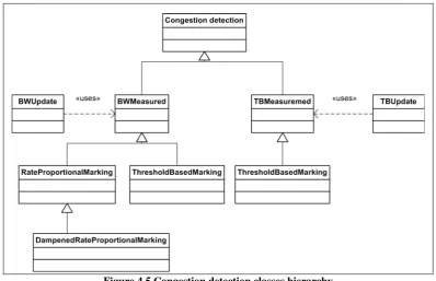
node, denoted as “affected DSCP”, and the second will be used to inform the rate of congestion, denoted as “encoded DSCP”. The mechanism used is called rate proportionate marking. In other words the number (or rate) of marked data packets is proportional to the level of the severe congestion.
Each interior node counts how many bytes in total arrive in one measurement period (Ntot). Then it calculates how many bytes are above the congestion threshold (Nsc). The level of congestion is calculated as the ratio between the bytes above the threshold and the total passing bytes – Nsc/Ntot. The node marks number of bytes equal to the congestion level (Nm) and remembers that number. In the next measurement period the same procedure is followed only the number of bytes to mark is decreased with Nm, resulting in Nsc/Ntot - Nm. This is a sliding window mechanism where the window size is the number of periods for which the node keeps memory. If the memory is not big enough the node will mark more than the necessary bytes to solve the congestion or in other word it will undershoot.
Severe congestion handling when data packets are marked
In order to solve the severe congestion flows that contribute to the severe congestion, have to be terminated. Edge nodes can do that based on the proportion of severe congestion they learn from the interior nodes. The proportion of the severe congestion is calculated by measuring the rate of the marked (as “encoded DSCP”) packets that are arriving at the egress node. The total number of marked bytes gibes the total congested bandwidth.
Each flow has reserved a certain bandwidth. The number of flows to be terminated should be chosen such that the sum of their reserved bandwidth is larger than the total congested bandwidth. A flow is chosen for termination and its bandwidth is subtracted from the total congested bandwidth. If the result of the subtraction is still positive, another flow has to be terminated and so on. Given that certain PHB class messages are marked as severe congested, only flows from the same PHB class should be terminated.
When more than one flow priorities have to be supported within one PHB class flow termination will start from the flows with lower priorities. If their bandwidth is not enough to solve the severe congestion, the calculation step moves one priority level above. The mechanism is specified in [BaWe06].
The interior nodes will mark bytes per PHB group not considering the packet priority. In order to keep the priority principle the edge node, after all marked flow are stopped, should move to the affected flows from the same priority before it goes on to the next priority level. The particular criterion to choose flows is an implementation decision. It is possible to begin from the biggest flows within a priority class, from the smallest flows or with the flow which bandwidth is the closest to the total severe congested bandwidth.
3.5 RMD QoS NSLP Unidirectional Operation
3.5.1 Successful reservation procedure
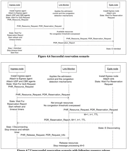
A reservation procedure is the sequence of processes connected with initiation of a reservation request, its propagation in the data path, the check up of available resources in the interior nodes on the data path, creation of reservation states and generation of response for the result of the resource request. When all nodes on the data path can support the reservation request, the reservation procedure is called to be successful. The message sequence and the state changes are shown on Figure 3.11.
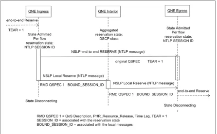
The ingress node, after it admitted the requested resources and has installed a reservation state, generates two messages – one end-to-end and one local intra domain RESERVE message. The end-to-end RESERVE message should not be processed in the interior nodes and therefore it uses different RAO (Router Alert Value) than typically. The local RESERVE message is initiated by the ingress node and it carries a RMD-QOSM QSPEC. It is the responsibility of the ingress node to bind the two messages and to inform the egress about that relation using the BOUND_SESSION_ID.
The interior nodes apply the admission control mechanism and during a successful reservation, the reservation state is increased with the requested resource units. When the egress receives the local RESERVE it binds it with the corresponding end-to-end RESERVE message. The end-to-end RESERVE is forwarded (the reservation is successful) but with removed marking, used to bypass the interior nodes.
When a successful RESPONSE is received at the egress it is sent back directly to the ingress. The ingress has to transmit the RESPONSE message further so the data initiator is informed and can start transmission of the user data. Using the BOUND_SESSION_ID the local RESPONSE can be related to the proper per-flow end-to-end reservation state in the edge nodes.
3.5.2 Unsuccessful reservation procedure
In the cases when one or more of the nodes on the data path cannot accept the RESERVE message the reservation procedure fails. This is called unsuccessful reservation procedure and it is presented in Figure 3.12. In such situations additional measures should be taken so the data initiator is notified about the failed request and the network state is the same as before the request was made.
NSIS framework signaling protocols
3.5.3 Refresh procedure
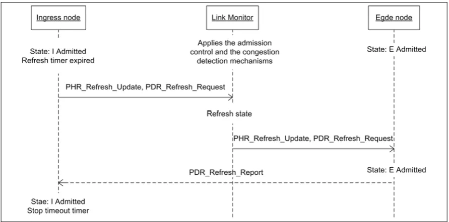
As it was mentioned, QoS NSLP is a soft state protocol and as such the states that it installs have limited lifetime. When this lifetime has expired if the signaling application has not re-confirmed the reserved resources they are freed and can be occupied by other sessions. To keep the reservation active a refresh procedure is initiated – before the reservation lifetime has expired a (refresh) RESERVE message is sent to re-confirm the used resources.
The refresh procedure appears only in the reservation based method since it keeps reservation states. A full description of the procedure and the message fields values are given in [BaWe06].
The ingress node is responsible for the generation of the (refresh) RESERVE messages. Each interior node refreshes the resources specified in the Bandwidth parameter of the refresh message. The reservation state in each refresh period is actually rebuilt оr the reserved resources per each class start from zero and are re-created based on the refresh messages. In case the refresh is unsuccessful, the message is M marked to inform the edge node about the unsuccessful refresh.
The Egress node has the responsibility to generate a RESPONSE message, built upon the fields of the (refresh) RESERVE message. The egress node uses the SESSION_ID, carried by the (refresh) RESERVE message, to identify the ingress that has to receive the RESPONSE.
3.5.4 Release procedure
When an existing reservation is no more requested or due to some network changes it is rejected, the reservation state has to be deleted. A special (release) RESERVE message is used to free the resources used by the particular session.
During the release procedure an interior reduced state node that receives a (release) RESERVE message should release the resources for the signaled session. This is done by subtracting the resource units specified in the message from the current reservation state for the PHB class. The PHB class reservation state is recognized using the DSCP value of the (release) RESERVE message. Before the state is released, it has to be calculated if the release is for this refresh period or for the previous one. If the message was sent for the previous refresh period the resources were automatically released and when the node decreases the current reservation state it actually releases resources of another session. A special value, called Time Lag is carried by the (release) RESERVE. Time Lag contains the time difference between the last refresh and the release generation. The same difference is calculated in each node processing the release message. The resources will be released only if the value withdrawn from Time Lag is smaller than the calculated. The exact calculation procedure can be found in [BaWe06].
NSIS framework signaling protocols
Figure 3.13 Refresh procedure
3.5.4.1
Release due to T marked RESERVE message
A RESERVE message with set TEAR flag indicates desire of the initiator to stop the session. The TEAR flag informs the NSIS aware nodes that a release procedure should start (Figure 3.14). The procedure is very familiar to the reservation establishment procedure with some difference in field settings and the reservation state management. The (release) RESERVE will trigger precondition check and afterwards release of resources. This process happens in each node on the path of the message.
Along with a local RESERVE message an end-to-end RESERVE message is sent. At the egress node both messages are coupled and the end-to-end message is processed further only if the local message has arrived. The end-to-end message, just as in the reservation request scenario, is marked to bypass the interior nodes in the domain.
3.5.4.2
Release due to M marked RESPONSE
are equal the node is the last one that made successful reservation. The release message should not be forwarded otherwise it would release resources of other sessions.
Figure 3.14 Release procedure triggered by T marked RESERVE
3.5.4.3
Release due to S marked RESPONSE
In a congestion detection procedure using the refresh messages a RESPONSE is S marked. The (release) RESERVE message will be marked with M=1 and S=1 and it will not be terminated in the interior nodes. The message has to release resources on the whole path and to reach the egress node. Again the reservation state for the correct PHB class is decreased by subtraction and using the Time Lag. The message exchange is presented on Figure 3.16 and the header precise filed setting can be found in [BaWe06].
3.5.4.4
Release due to NOTIFY message
NSIS framework signaling protocols
Figure 3.15 Release procedure triggered by M marked RESPONSE
Figure 3.17 Release procedure triggered by NOTIFY
NSIS framework signaling protocols
Figure 3.19 Unsuccessful reservation procedure for reverse direction
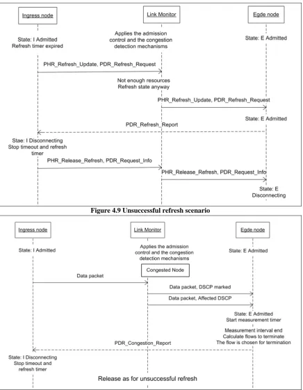
3.5.5 Severe congestion procedure
The message sequence of the severe congestion procedure based on data marking, as presented in section 3.4.3.2, is depicted in Figure 3.18.
An interior node can discover a severe congestion situation occurrence by using the severe congestion detection mechanism. It will then use the specified marking procedure to inform the egress node about the level of the severe congestion. In the egress the severe congestion handling mechanism will be used. For every flow that has to be stopped, the egress sends NOTIFY towards the ingress node. The NOTIFY message will have an INFO SPEC with the following information – Error class: Transient failure, Error code: Transient RMF related error and Error sub-code: Severe congestion. It is very important is that the original DSCP values of the data packets should be restored, otherwise the severe congestion handling mechanism can be applied by the next domain, which may cause problems.
The last step is the release procedure in the ingress node when the marked flows are stopped as it was discussed in chapter 3.5.4.4.
3.6 QoS NSLP Bidirectional Operation
3.6.1 Successful and unsuccessful reservation procedure
reservation procedure can be also seen in Figure 3.19 with the difference that the last RESESRVE message is not M marked.
A node that does not have enough available resources can be located on the forward as well as on the reverse path. Thus two scenarios of unsuccessful reservation procedures are possible. When the reservation fails on the forward path the procedure is the same as presented in Figure 3.12. If the reservation fails on the reverse path the RESERVE message from egress to ingress will be M marked (Figure 3.19). The full description of the procedures is given in [BaWe06].
3.6.2 Refresh and release procedure
Both procedures are very similar to the procedures for the unidirectional scenario. The schemes that were presented in sections 3.5.3 and 3.5.4 can represent the bi-directional operation with only one difference – the egress sends to the ingress a RESERVE message that carries in its PDR container the response for the forward direction. The RESERVE messages on the reverse path are processed by all nodes on the path. When the ingress receives the RESERVE it learns the result for both directions – the PDR container informs for the forward and the PHR container for the reverse. For in detail explanation of the changes in the message fields [BaWe06] can be consulted.
3.6.3 Severe congestion procedure
Just as in the case of reservation procedure the data flow g