Analysis of Output DC Current Injection in
Grid Connected Inverters
Sneha Sunny George1, Robins Anto2, Sreenath B3
PG Scholar, Department of EEE, Amal Jyothi College of Engineering, Kanjirappally, Kottayam, Kerala, India1
Assistant professor, HOD, Department of EEE, Mar Baselios Christian College of Engineering and Technology,
Peerumade, Kerala, India 2
Assistant professor, Department of EEE, Amal Jyothi College of Engineering, Kanjirappally, Kottayam, Kerala, India 3
ABSTRACT: Solar energy technologies have gained much importance in the recent scenario due to their ability to produce clean, reliable, useful power. Grid connected Photovoltaic system requires conversion from DC to AC to harness the useful energy produced. A Photovoltaic inverter directly connected to the grid can cause, besides the generation of several current harmonics, a DC current component injection. Excessive DC current injection into the AC network can result in problems such as increased corrosion in underground equipment and transformer saturation. The paper aims at evaluating the output DC-current injection in grid connected inverter used for a 100kW solar power plant installed at Amal Jyothi College of Engineering, Koovapally, through experimental analysis. A simulation based study on output DC current injections in inverters with two different multilevel topologies is also conducted.
KEYWORDS:Grid connected inverter, DC offset current
I. INTRODUCTION
With the increase in energy crisis concerns growing during day by day, much recognition is being gained in the potential of solar energy as a sustainable energy source . Solar energy adds flexibility to the energy resource mix by decreasing the dependence on fossil fuels, but the greatest barrier to the technological expansion in this field is the costs of devices used for converting sun`s energy in the form of radiation into useful electrical energy, limited space and energy. Even though there has been a massive downward tendency in the price of PV modules, the price of grid connected inverters still remains high thereby increasing the overall cost. The efficiency of the plant plays a crucial role in the profit obtained from sustainable energy resources being harnessed. The major benefit of designing a reliable, stable, efficient and lower cost photovoltaic power electronics system is the availability of reliable and quality power without relying on the utility grid. It also avoids the major investment in transmission and distribution. To the nation, the major benefit lies in the fact that it reduces greenhouse gas emissions, responding to the increasing energy demands by establishing a new, high-profiled industry.Therefore, it is required to minimize the losses and improve the efficiency of power electronic devices used. Use of multilevel inverters has increased the quality of waveforms and thereby increasing efficiency of the system. H-bridge multilevel inverters are more suitable for renewable energy harvesting due to the presence of separate DC sources.
II. GRID CONNECTED INVERTER AND DC INJECTIONS
Due to approximate short circuit characteristics of AC network, a little DC voltage component can accidently be produced by grid connected inverters which can create large DC current injections. If output transformers are not used, these inverters must prevent excessive DC current injection, which may cause detrimental effects on the network components, in particular the network transformers which can saturate, resulting in irritant tripping. This may also increase the losses and reduce the lifetime of the transformers, if not tripped. Moreover, the existence of the DC current component can induce metering errors and malfunction of protection relays and can create an adverse effect on the overall functioning of the solar power plant.
Therefore, there are stringent regulations in many countries to prevent the network from the large DC current injection. Since most Indian standards published by BIS are aligned to IEC standards, DC injections up to ±1% is being proposed by the BIS in the Indian standard keeping with IEC 61727. The H-bridge or Multi Level inverter eliminates the DC component of the current by adding switches on the DC side to clamp the voltage during the zero voltage periods. This method could be also applied by clamping in the AC side. Both methods could not guarantee elimination of DC component as the unbalance due to forward power electronic switch voltages and PWM control can not be removed. [4-6]
There are many types of multilevel inverter topologies in its history.The diode-clamped utilizes a bank of capacitors to split the DC bus voltage and then the switched flying capacitor (or capacitor clamped) topology. For a DC bus voltage Vdc, the voltage across each capacitor is Vdc/4 and voltage stress on each device is limited to Vdc/4 through the clamping diode. The principle of diode clamping to DC link voltages can be extended to any number of voltage levels. Since the voltages across the semiconductor switches are limited by conduction of the diodes connected to the various DC levels, the inverter is called DCMLI. The H-Bridge inverter consists of two series connected H-bridge cells, which are fed by independent voltage sources. The outputs of the H-bridge cells are connected in series such that the synthesized voltage waveform is the sum of all of the individual cell outputs.[7-11]
III. EXPERIMENTAL RESULT
The main objective of the work is to conduct an analysis study of output DC injection in grid connected inverter installed at the 100kW solar plant in Amal Jyothi College of Engineering, Kanjirappally, India. Technical analysis of the plant is done to evaluate the effect of environmental and climatic conditions on the performance of the system. The analysis also evaluates the effects DC offset to variations in its operating conditions. The International Energy Agency (IEA) Photovoltaic Power Systems Program describes, in its IEC Standard 61724, the parameters used to assess the performance of solar PV systems.
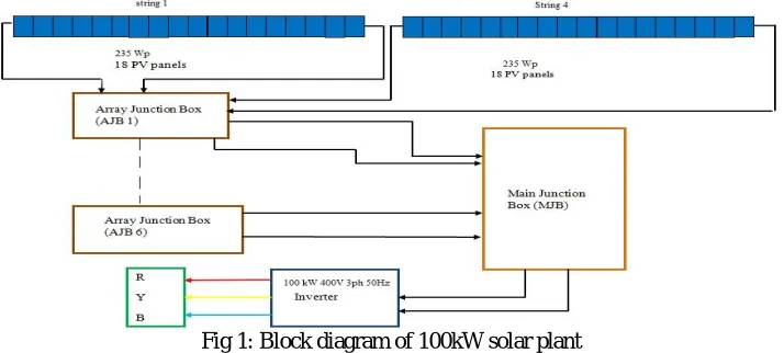
Fig 1: Block diagram of 100kW solar plant
supply using a VACON built inverter.The energy harnessed from the sun is used to meet the requirements of an entire 7-storey building block. When the energy harnessed is not sufficient the required amount is taken from the KSEB grid.
Since Kerala is placed in the equatorial region, it has high solar insolation and temperature. The normal ambient temperature varies from 23-33degC. The variation in solar insolation and temperature affects the panel PV panel performance. Rise in temperature results in degradation of efficiency and power output of the solar panel. The solar insolation falling in the earth`s atmosphere has direct or beam radiation,diffused radiation and albedo or reflected radiation. In bright sunshine days, the beam and albedo radiations are greater . But that during cloudier days the diffused components are more. The data collection was made for sunny and rainymonths ie in the months of February, march, April and May. From, the analysis of the available data, it is found that the panel has different behavior for varying insolation,temperature etc. From the experimental Datas collected, the efficiency of the inverter has reached up to 87% during high radiation time i.e.the inverter is never operating near at its full capacity and the average DC to AC conversion is below 90%.The inverter efficiency very slowly declines after peak value is reached.PV system at its best is operating in the 20 to 40% range of rated output and hence is operating in the 87 to 91% efficiency range during the sunniest periods. Since the inverter is kept in a mechanical room under the roof and the temperature differences was not as drastic as they would be for inverters located outside.
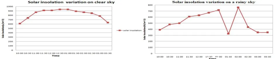
Fig 2. Solar insolation vs Time on a rainy day (a) and clear day (b)
From the analysis done, on a clear day with bright sunshine the panel receives daily average solar radiation of about 4.56kW/m2 to 5.24kW/m2. During the rainy days the solar radiation is about 3.13kW/m2 to 4.3kW/m2. Thus from the data collection it can be classified into two groups. First, high solar radiation groups that is available from January to mid April. The average solar insolation available over the region from the online satellite data the solar radiation available is in the range of 5 to 6kW/m2 for sunny hours and is around 4kW/m2 for rainy hours. The plot describes the solar radiation for sunny and rainy days.
Fig 4. solar insolation vs DC offset on a rainy day & clear day
The VACON 8000 SOLAR inverters use special digital control techniques to limit the DC offset in the output obtained from the inverter. When solar insolation is below the required value ( i.e.DC output voltage of solar panels is less than 340V) or when a fault occurs the inverter shutdowns and starts only 5mins after the fault condition is restored. This results in an error the value (357.67 %)of DC offset measured using FLUKE power analyzing meter. During March - mid April 2014 time period, the DC o_set varies between 0.04 (during high solar insolation) -0.19(During low solar-insolation) percent and during mid April- May 2014 time period,the DC offset varies between 0.03 during high solar insolation to 0.15 during low solar radiation time period. The maximum allowed DC offset in India is 1 % of the output obtained.
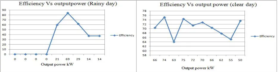
On analytic calculation of the PV inverter efficiency, it was found that between during the course of the experiment conducted between March to May on a sunny / clear day the efficiency of the 100 kW inverter was found to be 82.6%. Similarly for a rainy day the average efficiency of the inverter is calculated to be 80.23%. This can even drop if the solar insolation considerably drops. The daily average PV inverter output generation and efficiency can be noted to be 360kWh/day at 82.26% efficiency for a clear sky and about 200kWh/day at 80.23% efficiency for a rainy day.
Fig 3. Efficiency Vs output power on a rainy day & clear day
IV. SIMULATION AND RESULT
Both Diode Clamped and H-bridge multilevel inverter circuit were simulated with PWM control technique. Figure1 shows the simulation of Diode clamped Multi level inverter. Each PV source used consists of a 36W PV panel, a boost converter for DC-DC converter and a filter to reduce the effect of noise in the output. Fig 5 shows the output waveform of five level Diode Clamped Multi Level Inverter. Figure 2 shows the result of FFT analysis conducted. The FFT analysis is done to evaluate the amount of DC component in the fundamental wave form.
Fig.5 : Output waveform of DC MLI
Fig.6 FFT Analysis on DC MLI
From the FFT analysis conducted on the system, it was found that for a fundamental value of 178.5 peak126.2 rms) at 50Hz, the amount of DC component present is 6.713. i.e. about 3.76% of the fundamental. According to BIS the total allowable DC component is ±1% of the fundamental. Therefore the standard limits are crossed in this case at a carrier frequency of 2500 Hz for PWM control. Figure 4 shows the Simulation of H- Bridge MLI.
Figure 7 and 8 shows the output waveform and the FFT analysis conducted on H- Bridge Multilevel inverter for the comparative study between the two multilevel topologies.
Fig.8 FFT analysis conducted on H-Bridge MLI
From the FFT analysis conducted it was found that for a fundamental frequency of 50Hz with a carrier frequency of 2500Hz used for PWM signal generation, the Total Harmonic Distortion is 12.39% and the DC component is 0.08086 for a fundamental of 211.2 peak(149.4 RMS).i.e. about 0.03% of the fundamental. This value is below the standard limits.
TABLE I. FFT ANALYSIS OF 5LEVEL MLI TOPOLOGIES
Sl.No
FFT ANALYSIS RESULT
MLI Topology
Carrier Frequency
(Fc)Hz
DC component
% of fundame
ntal
1 DCMLI 2500 6.713 3.76
2 H-Bridge MLI
2500
0.0806 0.03
The table given above shows the comparative study of the two multilevel inverter topologies under study with respect to the DC component present in each system.
V. CONCLUSION
REFERENCES
1. Yanqing Li, Cheng Chen, Qing Xie, “Research of An Improved Grid-connected PV Generation Inverter Control System,” 2010 International Conference on Power System Technology, pp.1-6, 0ctober 2010
2. E. Koutroulis, F. Blaabjerg, “Methodology for the optimal design of transformerless grid-connected PV inverters,” IET Power Electron., Vol. 5, Iss. 8, pp. 1491–1499, 2012, June 2012
3. Angelina Tomova, TU Sofia, “Grid connected pv inverter topologies: an overview,” Phd Seminar, DERlab Young researchers,Glasgow, UK, April, 2011
4. Berba. F, Atkinson David, Armstrong. M, “Minimisation of DC current component in transformerless Grid-connected PV inverter application,” Environment and Electrical Engineering (EEEIC), 2011 10th International Conference, pp.1-4 May 2011
5. Salas, E. Olías , M. Alonso , F. Chenlo and A. Barrado, “DC current injection into the network from PV grid inverters,” Photovoltaic Energy Conversion, Conference Record of the 2006 IEEE 4th World Conference, pp. 2371 – 2374, May 2006
6. Ashraf Ahmed, Ran Li, “Precise Detection and Elimination of Grid Injected DC from Single Phase Inverters,” International Journal of Precision Engineering and Manufacturing, Vol. 13, No. 8, pp. 1341-1347, August 2012
7. J. Rodriguez, J.-S. Lai, and F. Z. Peng, “Multilevel inverters: A survey of topologies, controls, and applications,” IEEE Trans. Ind. Electron., vol 49, no. 4, pp. 724–738, Aug. 2002.
8. S.Busquets-Monge,“Multilevel Diode-Clamped Converter for Photovoltaic Generators With Independent Voltage Control of Each Solar Array,” IEEE trans. Ind. Electron., vol.55, no. 7, pp. 2713–2723, .July 2008
9. C. R. Balamurugan, S. P. Natarajan, R. Bensraj, “ Investigations on Three Phase Five Level Diode Clamped Multilevel Inverter,” International Journal of Modern Engineering Research (IJMER), Vol.2, Issue.3, pp-1273-1279, May-June 2012
10. Divya Subramanian, Rebiya Rasheed, “Five level cascaded h-bridge multilevel inverter using multicarrier pulse width modulation technique,” International Journal of Engineering and Innovative Technology (IJEIT) , Vol 3, Issue 1, pp. 438-441, July 2013.
11. Abdelaziz Fri, Rachid el Bachtiri, Abdelaziz el Ghzizal, “A cascaded h-bridge three-phase multilevel inverters controlled by multi-carrier spwm dedicated to PV,” Journal of Theoretical and Applied Information Technology, Vol. 58 No.2, pp 243-227, December 2013. [12]
Kitamura. A, Yamamoto. F, Matsuda. H, Akhmad. K,
Hamakawa,Yoshihiro,“Test results on DC injection phenomenon of gridconnected PV system at Rokko test center”Photovoltaic Specialists Conference, 1996, Conference Record of the Twenty Fifth IEEE, Page(s): 1377 - 1379 , 1996
12. N. Pandiarajan and Ranganath Muthu,"Mathematical Modeling of Photovoltaic Module with Simulink," International Conference on Electrical Energy Systems (ICEES 2011), pp.3-5, Jan 2011
13. H. Wilk, D. Ruoss, and P. Toggweiler, "Report - Innovative electrical concepts," International Energy Agency Photovoltaic Power Systems, IEA PVPS ,2002, www.iea-pvps.org
14. Yogi Goswami, Frank Kreith, Jan F.Krieder , Principles of Solar Engineering, Second edition, 1999.
15. Singla and Vijay Kumar Garg, "Modeling of solar photovoltaic module & effect of insolation variation using matlab/simulink," International Journal of Advanced Engineering Technology, Vol IV Issue III Article 2 pp.05-09 July-Sept,2013
16. Photovoltaic Inverter, WWW.pvresources.com/balance of system/inverters.aspx
17. Report on "CP4742 Grid Connected Renewable Energy System Technical Guidelines," pp. 1-18, October 2009
18. Matthew Armstrong, "Auto-Calibrating DC Link Current Sensing Technique for Transformerless, Grid Connected, H-Bridge Inverter Systems," IEEE Transaction on power electronics Vol. 21 No. 5, 2006.
19. V. Salas, M. Alonso and F. Chenlo, "Overview of the legislation of DC injection in the network for low voltage small grid-connected PV systems in Spain and other countries", Renewableand Sustainable Energy Reviews, vol. 12, pp. 575-583, 2008.
20. Carrasco, J. M., Franquelo, L. G., and Alfonso, N. M., "Power Electronic systems for the grid integration of renewable energy sources: A survey," IEEE Transactions on Industrial Electronics, Vol. 53, No. 4, pp. 1002-1016, 2006.
21. Report on "An investigation of dc injection levels into low voltage ac powersystems" Distributed generation co-ordinating group, june 2005 22. Instruction book for 10-200kW Standalone Drivers, Vacon 8000 Solar
23. Guidlines for measurement, data exchange and analysis of PV system performance
24. Frank Vignola, Fotis Mavromatakis and Jim Krumsick, "Performance of PV
inverter",www.solardat.uoregon.edu/download/papers/performance of inverters.pdf
25. S. Pless, M. Deru, P. Torcellini, and S. Hayter, "Procedure for Measuring and Reporting the Performance of Photovoltaic Systems in Buildings,” Tech[25]nicalReport NREL/TP-550-38603, October 2005
26. G.Chicco, R.Napoli and F.Spertino, "Experimental evaluation of the performance of grid-connected photovoltaic systems", Proc. IEEE Melecon 2004,Dubrovnik, Croatia 3, PP. 1011-1016 May 12-15, 2004.
27. B. Marion, J. Adelstein, and K. Boyle, H. Hayden, B. Hammond, T. Fletcher, B. Canada, and D. Narang, D. Shugar, H.Wenger, A. Kimber, and L. Mitchell and G. Rich and T. Townsend (2005), "Performance Parameters for Grid- Connected PV Systems”, 31st IEEE Photovoltaics Specialists Conference and Exhibition Lake Buena Vista, Florida, January 3-7, 2005