Comparison between IC and Fuzzy Logic
MPPT Algorithm Based Solar PV System
using Boost Converter
Mukesh Kumar
1, Dr S.R.Kapoor
2, Rajkumar Nagar
3, Amit Verma
4Associate Professor Dept. of Electrical Engineering, University College of Engineering, Kota, India2
PG Student, Dept. of Electrical Engineering, University College of Engineering, Kota, India1,3,4
ABSTRACT: The Solar power varies mainly depends on the weather conditions. Many new algorithms have been
projected to track the maximum power point (MPPT) of the solar system. This paper, presents a comparative study of two intelligent control methods in order to optimize the efficiency of the solar PV system. This paper presents in details comparative study between Incremental conductance algorithm and fuzzy Logic controller algorithm applied to a DC-DC Boost converter device. The Boost converter increases output voltage, it is depends on the duty cycle of switch device. The proposed controllers are adjusting the duty cycle of the DC-DC converter switch to track the maximum power of a solar PV array. Finally performance comparison between Incremental conductance and Fuzzy logic controller method has been carried out which has result shown the effectiveness of Fuzzy controller to draw more energy, decreases fluctuations and fast response, against change in variable weather condition. The final result show the fuzzy logic controller exhibits a better performance compared to Incremental conductance.
KEYWORDS: Photovoltaic System, Maximum Power Point Tracking, Boost Converter, Incremental Conductance
Algorithm, Fuzzy logic Controller.
I. INTRODUCTION
ISSN (Print) : 2320 – 3765 ISSN (Online): 2278 – 8875
I
nternational
J
ournal of
A
dvanced
R
esearch in
E
lectrical,
E
lectronics and
I
nstrumentation
E
ngineering
(An ISO 3297: 2007 Certified Organization)
Vol. 4, Issue 6, June 2015
II. PROPOSED SYSTEM
The proposed system consists of a PV array connected to a dc-dc boost converter and regulated the step-up output voltage. The boost converter input duty cycle adjusting by the MPPT controller, it is use to track the maximum power from solar array. The block diagram of the proposed system is shown in Fig.1.
Fig.1 Block diagram of the proposed system
III. MODELING OF PV SYSTEM
A solar PV cell basically is a p-n semiconductor junction. When exposed the light on the solar panel, a dc current varies linearly with the solar PV irradiance. The equivalent electrical circuit of an ideal PV cell can be treated as a current source parallel with a diode shown in Fig. 2.
Fig.2.Equivalent electrical circuit of a solar cell
The basic equitation from the theory of semiconductors that mathematically describes the I-V characteristic of the ideal PV cell is:
Id
I
I
pv,cell
(1)Where,
1
)]
[exp(
,
,
kT
qV
cell
Io
cell
Ipv
I
(2)Therefore,
[exp(
)
1
]
(
)
Rp
RsI
V
Vt
RsI
V
Io
Ipv
I
(3)Id: The Shockley diode equation
Io,cell: The reverse saturation current of the diode
q: electron charge (1.60217646*10^-19c)
k: Boltzmann constant (1.3806503*10^-23)
T: cell Temperature in Kelvin (k)
V: solar cell output voltage (V)
Rs: solar cell series resistance (Ω)
Rp: solar cell parallel resistance (Ω)
When the cells connected in parallel which Increases the current and the cells connected in series provide greater output voltage. The various equations describing the PV cell characteristics are using suitable mathematical blocks from the MATLAB Simulink library [2,3,6].This Simulation is done for standard test condition, when temperature is 25̊C and Irradiation is 1000W/m^2[9,10,11,12].
Fig.3 P-V & I-V characteristic of PV array
IV.DC-DC BOOST CONVERTER
A Boost converter is a step-up DC-DC power converter, which is converting a low input voltage to a high output voltage. In this situation the output current is lower than source current. It is implemented in this proposed system by using a diode and MOSFET [21]. The converter operation can be divided into two modes, mode first begins, when the transistor is switched on, the current increases linearly in the boost inductor, and the diode is off state, mode second begin, when the transistor is switched off, the energy stored in the inductor is discharge through the diode to the source load [19,20]. The classical relationship between input and output voltages of a boost converter at steady state condition is given by
D
Vi
Vo
1
1
(4)
ISSN (Print) : 2320 – 3765 ISSN (Online): 2278 – 8875
I
nternational
J
ournal of
A
dvanced
R
esearch in
E
lectrical,
E
lectronics and
I
nstrumentation
E
ngineering
(An ISO 3297: 2007 Certified Organization)
Vol. 4, Issue 6, June 2015
Fig. 4 Boost converter circuit
V. MAXIMUM POWER POINT TRACKING
When a solar PV module is used in a system, its operating point is decided by the load, which it is connected to Solar radiation falling on a PV system module varies throughout the day, the operating point of module also changes throughout the day. A typical solar panel converts only 30% to 40% of the incident solar irradiation into electrical energy. In case of sun tracking, PV modules are rotated mechanically so that the radiation intercepted by a module is maximum power generation under a given condition, while in case of MPPT, electronic circuitry is used to ensure that maximum amount of generation power is transferred continue to the load. The maximum power tracking mechanism makes use of an algorithm and an electronic circuit [23, 24]. The mechanism is based on the principle of impedance matching between load and PV array, which is necessary for maximum power transfer. Hence the problem of tracking the maximum power point reduces to an impedance matching problem. This impedance matching is done by using a dc-dc boost converter, this converter used for the impedance matched by change the duty cycle (D) of the switch.
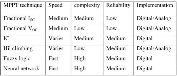
The power from the solar module is calculated by measuring the voltage and current. This power is an input to the algorithm which adjusts the duty cycle of the switch, resulting in the adjustment of the reflected load impedance according to the power output of PV array. Several method are presented for maximum power point tracking (MPPT) from photovoltaic system such as constant voltage method, Hill climbing method, perturbation and observation (P&O) method, Incremental Conductance (IC) method, open circuit voltage method, short circuit current method, Fuzzy logic controller method, Neural network etc. [7,8,14].
Table 1.1 Comparisons of Common MPPT Methods
MPPT technique Speed complexity Reliability Implementation
Fractional ISC Medium Medium Low Digital/Analog
Fractional VOC Medium Low Low Digital/Analog
IC Varies Medium Medium Digital
Hil climbing Varies Low Medium Digital/Analog
Fuzzy logic Fast High Medium Digital
Neural network Fast High Medium Digital
A. Incremental Conductance Controller Method
The Incremental Conductance algorithm is most commonly used in PV system application due to its easement of implementation and simplicity. The MPP is tracked by matching the PV array impedance with the effective impedance of the converter reflected across the array terminals. The Incremental conductance (IC) can be determine that the MPPT has reached the MPP and stop perturbing the operating point [16, 17]. If this condition is not met, the direction of the MPPT operating point perturbed can be calculated using the relationship between dP/dV and –I/V. this relationship is derived from the fact that dP/dV is negative, when the MPPT is the right side of the MPP and positive, when it is left side of the MPP, IC can track rapidly increasing and decreasing irradiance conditions with high accuracy. Disadvantage of this algorithm is the medium complexity and slow response, more fluctuations against change in weather conduction.
Fig.5 Flow chart of the Incremental conductance algorithm
Fig.6 Incremental conductance method
ISSN (Print) : 2320 – 3765 ISSN (Online): 2278 – 8875
I
nternational
J
ournal of
A
dvanced
R
esearch in
E
lectrical,
E
lectronics and
I
nstrumentation
E
ngineering
(An ISO 3297: 2007 Certified Organization)
Vol. 4, Issue 6, June 2015
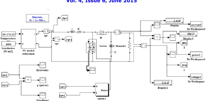
Fig.7 Simulink model for Incremental Conductance Algorithm
B. Fuzzy logic controller method
Fuzzy logic is a limb of Artificial Intelligence (AI), a branch of Engineering that deals with development of computer programs based on the study of human intelligence and nature of human thinking. The basic concept understanding fuzzy logic is that of a linguistic variable, that is a variable whose values are words rather than number (such as small and large). Fuzzy logic uses fuzzy sets to related classes of objects with unclearly defined boundaries in which membership is a matter of degree. The fuzzy logic system more is flexible rather than classical and conventional method. Fuzzy logic controller works with imprecise inputs, it does not need an accurate mathematical model. The fuzzy logic rules were first proposed by prof. L. zadeh in 1965 and can be implemented for the complex and unknown system. The IC method is not satisfied for the system especially for non-linear and complex system and cannot obtain the desire results [21, 23]. The structure of the fuzzy controller is based on the changing the control linguistic to form of the if-then in an automatic control system and best knowledge and experience can be more useful instead of understanding a technical behaviour of the system . In this system we use fuzzy logical operator, AND for Intersection, OR for union and NOT for complement [25]. The tracking of the maximum power point will be divided in two phase, the first phase is of tough research, with a significant step to improve the response of the MPPT controller and the second one is the final phase where the step is very small, thus ensuring the system stability and decrease the maximum oscillation around the MPP. The fuzzy controller consists of four functional blocks, fuzzification, fuzzy rule, an inference engine and the defuzzification. The fuzzy controller design contains the three following steps:
Fuzzification: In this process of fuzzification, converting the system actual input value E and CE into linguistic fuzzy labels using fuzzy membership function. These variables are expressed in different fuzzy levels: PB (positive big), PM (positive medium), PS (positive small), ZE (zero), NB (negative big), NM (negative medium), and NS (negative small), using basic fuzzy subsets.
TABLE 1.2: The twenty-five fuzzy rules subset
E /CE NB NS ZE PS PB
NB ZE ZE PB PB PB
NS ZE ZE PS PS PS
ZE PS ZE ZE ZE NS
PS NS NS ZE ZE ZE
The Fuzzy logic diagram is shown in figure, that is including two inputs of the FLC system are the error (E) and change of error (CE) that are defined by eq.(5,6). The output of Fuzzy logic is duty cycle (D) that should be operating to the Boost converter.
The error is given by:
)
1
(
)
(
)
1
(
)
(
)
(
k
Vpv
k
Vpv
k
Ppv
k
Ppv
k
E
(5)And the change in error is:
)
1
(
)
(
)
(
k
E
k
E
k
CE
(6)And the output of the controller is given by:
)
(
)
1
(
)
(
k
D
k
D
k
D
(7)ISSN (Print) : 2320 – 3765 ISSN (Online): 2278 – 8875
I
nternational
J
ournal of
A
dvanced
R
esearch in
E
lectrical,
E
lectronics and
I
nstrumentation
E
ngineering
(An ISO 3297: 2007 Certified Organization)
Vol. 4, Issue 6, June 2015
Fig.9 Internal structure of the fuzzy logic system
Fuzzy Rule base and inference engine: Fuzzy rule base is a combination of if-then functions that are used for the fuzzified all inputs for the controlled parameters. Fuzzy rules dependent on operation of the system and experience. In this study, the fuzzy rules include twenty-five fuzzy control rules with specific range of membership functions being considered fuzzy inference engine is an operating process method that formulates a logical decision based on the fuzzy rule. The fuzzy rules should be transferred into fuzzy linguistic output. In this paper mamdani is fuzzy inference method has been used with max-min operation fuzzy combination has been used.
Defuzzification: The process of defuzzification calculates the crisp output of the fuzzy logic controller. The output fuzzy data that is defined by converted to the numerical variable by creating the union of the output from each rule and converting a linguistic variable (fuzzy number) into a numerical variable (real number). In this paper, the center of gravity defuzzifier is used.
VI. SIMULATION RESULTS
Simulation of Incremental Conductance output Results
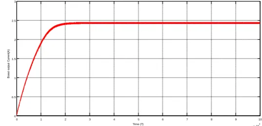
Fig.11 and Fig.12 shows the simulation results of boost output current and voltage, when incremental conductance MPPT method has been applied for the control duty cycle of boost converter. The current waveform is more stable and more efficient compare to without any MPPT method applied.
Fig. 11 The Boost converter output current with IC Controller
Fig.12 The Boost Converter output Voltage With IC Controller
0 1 2 3 4 5 6 7 8 9 10
x 104 0 0.5 1 1.5 2 2.5 3 Time (T) B o o s t o u tp u t C u rr e n t( A )
0 1 2 3 4 5 6 7 8 9 10
ISSN (Print) : 2320 – 3765 ISSN (Online): 2278 – 8875
I
nternational
J
ournal of
A
dvanced
R
esearch in
E
lectrical,
E
lectronics and
I
nstrumentation
E
ngineering
(An ISO 3297: 2007 Certified Organization)
Vol. 4, Issue 6, June 2015
Fig.13 show the simulation result of boost output power, when incremental conductance MPPT method has been applied for the control duty cycle of boost converter.
Fuzzy Logic output Simulation Results
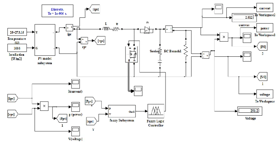
Fig.14 and Fig.15 shows the simulation result of boost output current and voltage, when fuzzy logic MPPT method has been applied for control duty cycle of boost converter. These current and voltage waveform are more stable and has more efficient compare to without any MPPT methods
Fig.14 The Boost output Current with Fuzzy logic controller
Fig.15 The output Voltage with Fuzzy logic controller
Fig.16 The Boost Converter Output Power with Fuzzy logic controller
0 1 2 3 4 5 6 7 8 9 10
x 104 0 0.5 1 1.5 2 2.5 3 Time(T) B o o s t o u tp u t C u rr e n t (A )
0 1 2 3 4 5 6 7 8 9 10
x 104 0 50 100 150 200 250 300 Time(T) B o o s t o u tp u t v o lt a g e ( V )
0 1 2 3 4 5 6 7 8 9 10
Fig.16 show the effect of fuzzy logic controller on the boost converter output power waveform , since it become constant at the maximum value(630.8W) after small settling time.
Comparative Results of IC controller and Fuzzy logic Controller
Fig.17 and Fig.18 shows comparative results of incremental conductance and fuzzy logic controller output current and voltage waveform .In these Fig. we have seen that current and voltage waveform due to fuzzy logic controller method are more stable and has less fluctuation compare to incremental conductance MPPT method. The fuzzy logic controller output current and voltage are 2.512A and 251.1V.The output current and voltage of incremental conductance are 2.440A and 244.6V respectively.
Fig.17 The Boost output current Results of IC controller and Fuzzy Logic controller
Fig.18 The Boost output Voltage Results of IC controller and Fuzzy Logic controller
0 1 2 3 4 5 6 7 8 9 10
x 10 4 0 0.5 1 1.5 2 2.5 3 Time (T) B oo st O ut pu t C ur re nt ( A )
Fuzzy and IC Comparative Simulation Output Current Results
Fuzzy IC
0 1 2 3 4 5 6 7 8 9 10
x 104
0 50 100 150 200 250 300 Time (T) B oo st o ut pu t V ol ta ge ( V )
Fuzzy and IC Simulation Comparative Output Voltage Results
Fuzzy IC 200 300 400 500 600 700 B oo st O ut pu t P ow er ( W )
Fuzzy and IC Simulation Output Power Results
ISSN (Print) : 2320 – 3765 ISSN (Online): 2278 – 8875
I
nternational
J
ournal of
A
dvanced
R
esearch in
E
lectrical,
E
lectronics and
I
nstrumentation
E
ngineering
(An ISO 3297: 2007 Certified Organization)
Vol. 4, Issue 6, June 2015
Fig.19 show boost output power using IC mathod and fuzzy controller is 598.2W and 630.8W respectively.
VII.CONCLUSION
This paper presents a comparative study between Incremental Conductance and Fuzzy Logic MPPT controller methods in Matlab/Simulink. The solar PV system main problem, efficiency low and cost is high, and output is change in cloudy weather conductions. So we need a effective MPPT controller. Finally performance of comparative study, we found that the Fuzzy Logic controller is effectiveness compare to IC controller. The Fuzzy Logic controller Increase output power, less fluctuation and fast Response, against change in weather conductions. The Fuzzy controller is superior compared to Incremental conductance.
REFERENCES
[1]. Vallalava M. G., Gazoli J. R., and Ruppert E. F., “Modeling and Circuit based Simulation of Photovoltaic Arrays”, Brazilian Journal of Power Electronics, vol. 14(1), pp. 35-45, October 2009.
[2]. Zainudin H. N., Mekhilef S., “Comparison Study of maximum Power Point Tracker Techniques for PV Systems”, Proc. of 14th International Middle East Power System Conference (MEPCON), Egypt, PP.750-755,Dec. 19-21, 2010
[3]. M.S. Khireddine, M.T.Makhloufi, A. Boutarfa., “Tracking Power Photovoltaic System With a Fuzzy Logic Control Strategy”, IEEE International Conference on CSIT, PP.42-49, 2014.
[4]. Shahrooz Hajighorbani, M.A.M. Radzi, M.Z.A.Ab Kadir, S.Shafie, Razieh Khanaki, and M. R. Maghami, “Evaluation of Fuzzy Logic Subsets Effects on Maximum PowerPoint Tracking for Photovoltaic System,” International Journal of Photoenergy, Volume 2014, Article ID 719126,pp.1-13, 2014.
[5]. Mohammad Seifi, Azura Bt. Che Soh, Noor Izzrib. Abd. Wahab, and Mohd Khair B. Hassan, “A Comparative Study of PV Models in Matlab/Simulink” International Science Index Vol:7, No.2, pp.102-107,2013.
[6]. Mei Shan Ngan, Chee Wei Tan., “A Study of Maximum Power Point Tracking Algorithms for Stand-alone Photovoltaic Systems” IEEE Applied Power Electronics Colloquium Malaysia, p.p.22-27, 2011.
[7]. Shilpa Sreekumar, Anish Benny, “Fuzzy Logic Controller Based Maximum Power Point Tracking of Photovoltaic System Using Boost Converter” IEEE ICCCNT Forth International conference, p.p. 1-6, July 4-6, 2013.
[8]. R.Mahalakshmi, Aswin Kumar.A., Aravind Kumar, “Design of Fuzzy Logic Based Maximum Power Point Tracking Controller for Solar Array for Cloudy Weather Conditions,” IEEE Power and Energy System: Towards Sustainable Energy, p.p.1-4, 2014.
[9]. Jenifer A., Newlin Nishia R., Rohini G., and Jamuna V., “Development of MATLAB Simulink Model for Photovoltaic Array”, Proc. of IEEE International Conference on Computing, Electronics and Electrical Technologies, Kumara Coil, Tamil Nadu, pp. 436-442, 2012.
[10].Youjie M., Deshu C., Xuesong Z., and Runrui G., “MPPT Control of Photovoltaic System based on Hybrid Modeling and its Simulation”,
Proc. of International Conference on Sustainable Power Generation and Supply, Nanjing, China, pp. 1-5, 2011.
[11].Zainudin H. N., Mekhilef S., “Comparison Study of maximum Power Point Tracker Techniques for PV Systems”, Proc. of 14th International Middle East Power System Conference (MEPCON), Egypt, 19-21, December 2010.
[12]. M. T. Makhloufi, M. S. Khireddine, Y. Abdessemed and A. Boutarfa, “Maximum Power Point Tracking of a Photovoltaic System using a Fuzzy Logic Controller on DC/DC Boost Converter” IJCSI International Journal of Computer Science Issues, Vol. 11, Issue 3, No 2, May 2014.
[13].Trishan Esram, Patrick L. Chapman, “Comparison of Photovoltaic Array Maximum PowerPoint Tracking Techniques” IEEE Transaction on Energy Conversion, Vol.22, No. 2, p.p. 439-449, June, 2007.
[14].Fangrui Liu, Shanxu Duan, Fei Liu, Bangyin Liu, and Yong Kang, “A Variable Step Size INC MPPT Method for PV Systems” IEEE Transactions On Industrial Electronics,Vol.55, No.7, p.p.2622-2628, July 2008.
[15].Qiang Mei, Mingwei Shan, Liying Liu, and Josep M. Guerrero, “A Novel Improved Variable Step-Size Incremental-Resistance MPPT Method for PV Systems” IEEE Transactions On Industrial Electronics, Vol.58, No.6,pp.2427-2434,June 2011.
[16].Bader N. Alajmi, Khaled H. Ahmed, Stephen J. Finney, and Barry W. Williams, “Fuzzy-Logic-Control Approach of a Modified Hill-Climbing Method for Maximum PowerPoint in Microgrid Standalone Photovoltaic System” IEEE Transactions On power Electronics,Vol.26,No.4,pp.1022-1030,April 2011.
[17].Vipin Padmanabhan, Beena V, and Jayaraju M, “Fuzzy Logic Based Maximum Power Point Tracker for a Photovoltaic System” IEEE power, signals, controls and computation international conference, p.p.1-6, 2012.
[18].Recep Cakmak, Ismail H. Altas, Adel M. Sharaf, “Modeling of FLC-Incremental Based MPPT using DC-DC Boost Converter for Standalone PV System” IEEE Innovations in intelligent system and applications, p.p.1-5, 2012.
[19].Mohammed A. Elgendy, Bashar Zahawi, David J. Atkinson, “Assessment of the Incremental Conductance Maximum Power Point Tracking Algorithm” IEEE Transactions On Sustainable Energy, Vol.4, No.1, Jan.2013.
[20].Snehamoy Dhar, R Sridhar, Geraldine Mathew, “Implementation of PV Cell Based Standalone Solar Power System Employing Incremental Conductance MPPT Algorithm” IEEE International Conference on Circuits, Power and Computing Technologies (ICCPCT), p.p.356-361, 2013.
[21].H.E.A. Ibrahim, Mahmoud Ibrahim, “Comparison Between Fuzzy and P&O Control for MPPT for Photovoltaic System Using Boost Converter” Journal of Energy Technologies and Policy, Vol.2, No.6, p.p.1-11, 2012.
[22].Govind Anil, “Fuzzy Logic based Maximum Power Point Tracker for a PV System” IOSR Journal of Electrical and Electronics Engineering, Vol.5, Issue 4, p.p.13-21,Jun.2013.
[23].S. Vasantharaj, G. Vinodh kumar, M. Sasikumar, “Development of a Fuzzy Logic based, Photovoltaic Maximum Power Point Tracking Control System using Boost Converter” Third International Conference on Sustainable Energy and Intelligent System, 27-29 Dec.2012.
[25]. Alireza Rezaei, S.Asghar Gholamian, A.Sheikholeslami, “Tracking the Maximum Power Point in Stand-alone Photovoltaic System by Fuzzy Logic Controller” Majlesi Journal of mechatronic system, Vol.1, No.4, p.p.46-52, dec.2012.
BIOGRAPHY
Mukesh Kumar was born in Gokulpura, Sikar Rajasthan in 1988. He received his B. Tech
(Electrical Engineering) from Sobhasaria Engineering College, Sikar (Rajasthan), India in 2011. Two years experience as a teaching assistant in RTU Kota. He received his M. Tech. (Power System) degree from University College of Engineering, RTU, Kota (Rajasthan), India in 2015. He is assistant professor in Department of Electrical Engineering at Sobhasaria Engineering College, Sikar (Raj.). His fields of interest solar power electronics and power converters, solar MPPT techniques, Fuzzy logic, renewable energy and solar photovoltaic systems.
Shashi R. Kapoor was born in Kota, Rajasthan in 1971. He received B. E. (Electrical) from the University of Rajasthan in 1993 and stood second in the University. He received his M. Tech. (System Engineering and Operations Research) degree for IIT Roorkee in 2003 and received Dr. J.C. Mukhopadhyay medal, Dr. Jai Krishna medal, Late Smt. Uma Goyal W/O Sri Uday Shankar Goyal memorial prize, Laxmi Devi and Shri Banadri Das prize for academic performance in M.Tech. He received his Ph.D. degree from Rajiv Gandhi ProdyogikiVishwavidyalaya (RGPV), Bhopal (M. P., India) in 2011.He joined Govt. Engineering College, Kota as Lecturer in 1999. Presently he is Associate Professor in Department of Electrical Engineering at University College of Engineering, Rajasthan Technical University, Kota (Raj.). His fields of interest are FPGA implementation of control algorithms of electrical motors, Microprocessors, Embedded systems, Artificial Intelligence and Optimization Techniques.
Rajkumar Nagar was born in Kota, Rajasthan in 1992. He received his B. Tech in
Electrical Engineering from Modi Institute of Technology, Kota (Rajasthan), India in 2013. He is pursuing his M. Tech. in Power Electronics and Electric Drives from University College of Engineering, RTU, Kota(Rajasthan), India. He is currently working towards his PG project in multilevel inverter topologies for solar photovoltaic systems.
Amit Verma was born in Bundi, Rajasthan in 1984. He received his B. Tech in Electronic
instrumentation and control Engineering from Poornima College of engineering, jaipur
(Rajasthan), India in 2006. He is pursuing his M. Tech. in Power System from University