Performance Analysis of Separately Excited
DC Motor using PI and FUZZY LOGIC
Controller
Kumar Shantanu1, Umesh Chand bind2
Research Scholars, Dept. of EEE, KNIT Sultanpur , Uttar Pradesh , India1,2
ABSTRACT:This paper contain the comparison analysis of two controllers (PI and Fuzzy logic controller) for speed control of dc motor using chopper circuit. The speed control is done by varying armature voltage using voltage controller , the firing angle of chopper is receive signal from controller and variable voltage is given to the armature of dc motor , the comparative result of both control scheme is graphically represented , the fuzzy logic controller reduces the current ripple and peak over shoot but is sluggish in nature , the simulation of result of both controller is presented in this paper using MATLAB/simulink
KEYWORDS: SED (separately excited dc motor), FLC (Fuzzy logic controller),PI (proportional integrator )
I.INTRODUCTION
In industrial application, an electric motor is one of the important component, as load on the motor is change frequently the speed of motor is also changes .For speed control of motor the drives are used; an electric drive consist of electric motor, power controller and energy transmitting shaft, and feedback loop using position or speed sensor electric drive are mainly of two type dc drive and ac drive. The dc drive is simple, less maintenance, easy to control and design is not very much complex as compared to ac drive, dc motor developed full load torque at low speed and its speed control range is from no load to full load speed, the controller use for controlling the firing angle of power electronic controller is obtain by the controlling the current using PI and Fuzzy Logic controller. The motor used in this paper is separately excited dc machine whose field winding is excited by dc source while armature gets the voltage from power electronic converter. The performance of PI and Fuzzy logic controller are presented using MATLAB/simulink.[1]
II.SEPRATELY EXCITED DC MOTOR
Separately excited dc motor is coupled is load as shown in fig1 its field winding is energised by dc source and its armature is supplied by the controller when the dc voltage is applied on the armature current is produces in the armature conductor through the brushes and commutator since the rotor is also energies by dc voltage hence due to interaction of the armature back emf and field flux torque is produces and armature rotates. Under steady state condition the load torque Tl opposes the electromagnetic torque Te.The proposed model is using the fully controlled bridge rectifier circuit whose firing angle is obtained from the closed loop circuit of armature current . The two output parameter which is obtained as the output is speed and torque as, torque varies linearly with the armature current if we
control the armature current; torque is controlled as the motor speed at load is a function of torque
(
T
J
d
B
)
dt
the speed of motor is also varied. If the armature current is to be controlled , it should be compared with the reference value with the help of controller the two controller which are used in the this paper is PI and FLC , the output of the controller set a voltage firing angle for fully controlled bridge rectifier .
MATHEMATICAL ANALYSIS OF SEPRATELY EXCITED DC MOTOR
For armature circuit : t a a a
dIa
V
E
I r
L
dt
(1.1)For field circuit :
V
f
I r
f * f (1.2)Motor back emf :
E
a
K
a
m (1.3)Electromagnetic torque:
T
e
K
a
I
a (1.4)Speed of motor:
a a a
m
a
V
I r
K
(1.5)From eq (1.5) the speed of motor is controlled by varying armature voltage known as armature voltage control method or by varying field flux field flux control method .
Dynamic model of dc motor:
At load m
d
T
J
B
dt
For transfer function tanking laplace of eq (1.1) and (1.6) we get:
( )
( )
( )
( )
( )
( )
( )
( )
( )
mt b a a a a
b b
m m a
T s
Js
s
B
s
V s
E s
I r s
sL I s
E
K
s
T s
K I
Fig 2 Block diagram of dc motor
( )
( )
(
)(
)
m
a a a b m
s
K
E s
R
sL
Js
B
K K
With load torque set to zero transfer function of current and input voltage is obtain
( )
( )
(
)(
) (
) ^ 2
I s
sJ
B
V s
sJ
B SL
R
Km
III. PHASE CONTROLLED RECTIFIER
Large dc motor drives are always fed through three-phase converter for their Torque and speed control , a three phase controlled converter feed power to armature circuit for obtaining speed below speed ,
Fig 3 Three phase controlled rectifier
negative group also fired at an interval of 120o , SCRs from both the group are conduct for 120o but SCRs from both the group are fired at an interval of 60o. at any time 2 SCRs one from both group conduct together the sequences are (T1T2,T2T3,T3T4,T4,T5,T5T6,T6T1) the output of the converter is an dc , [3]
o t
3
mlcos
V
V
V
IV Proportional Integral Controller
A PI is a proportional gain in parallel with an integrator; both in series with a lead controller. The proportional gain provides fast error response and stability but have an off set which is very mush eliminated by integral controller The integrator drives the system to a 0 steady-state error and reduces the off set error due to proportional controller[4]
MATHEMATICAL MODEL FOR PI CONTROLLER
PI controller is a combination of proportional controller (P) and integral controller (I):
K s
( )
K
pK
is
Fig 4: Block diagram of PI feed dc motor
The output of the current loop is fed first compare with the reference armature current the error signal is then feed to a PI controller the output of the PI controller is a fringing angle which is used to controlled the voltage for phase controlled rectifier the matlab block is :
IV. FUZZY LOGIC CONTROLLER
The fuzzy logic controller is an artificial intelligence technique. The unique property of Fuzzy logic is that it is tolerance for imprecision[9] that means if the system input is not precise it still give the more accurate output.
The fuzzy logic can be design for any control system in the following step: 1. Fuzzyfication:Membership functions used to graphically describe a situation. 2. Evaluation of Rule: Application of the fuzzy logic rules.
3. Diffuzfiication: Obtaining the crisp results.
A FLC convert the linguistic control strategy into the automatic control strategy.
In proposed model the two inputs for Fuzzy Logic is current error and change in current error and its output is firing angle for phase controlled rectifier for controlling of Dc motor
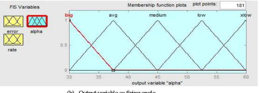
.Consider Fuzzy speed control system , where the input signals are E and CE and the output is firing angle reference are Fuzzified by assigning corresponding member ship functions to each signal .[5],[6],[7]
(a) Fuzzy Input variable rate of current
(b) Output variable as firing angle
In Fuzzy membership function there are two input variable and each input variable have seven linguist values, so 5x5=25 Fuzzy control rule are in the Fuzzy reasoning:
Table 1: Fuzzy Logic Control Rule error
Rate
N NZ Z PZ P
N BIG XLOW BIG XLOW XLOW
NZ XLOW XLOW MEDIUM LOW LOW
Z LOW MEDIUM AVG AVG MEDIUM
PZ AVG AVG LOW MEDIUM AVG
P MEDIUM BIG XLOW BIG BIG
V. RESULT AND DISCUSSION
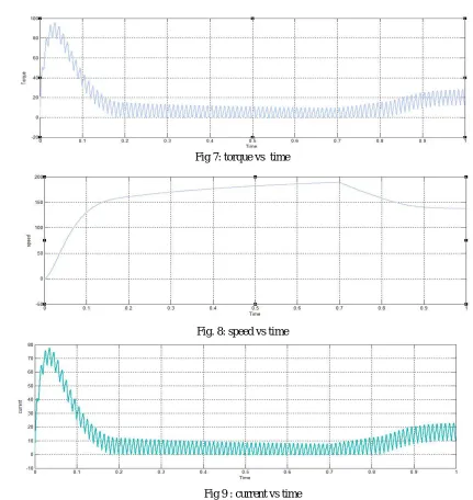
The dc motor drive using phase controlled rectifier and two different controller (PI and FLC) and their simulation using MATlab/simulation, for separately dc motor the field excitation is taken as 150 V , and field resistance is 1ohm , the reference value of armature current is 20 A , and a reference speed is taken as 184, a load of 20 Nm is applied at 0.7 sec , the simulation result of dc motor drive without any controller , PI and FLC ,
a) Simulation without any controller
Fig 7: torque vs time
Fig. 8: speed vs time
Fig 9 : current vs time
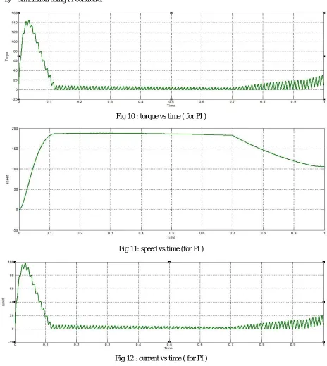
b) Simulation using PI controller
Fig 10 : torque vs time ( for PI )
Fig 11: speed vs time (for PI )
Fig 12 : current vs time ( for PI )
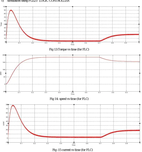
c) Simulation using FUZZY LOGIC CONTROLLER
Fig 13:Torque vs time (for FLC)
Fig 14: speed vs time (for FLC)
Fig :15 current vs time (for FLC)
d) Comparision of all the simulation :
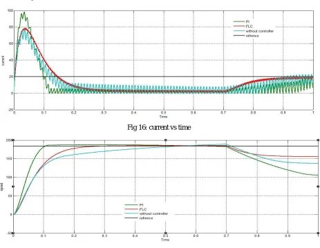
Fig 16: current vs time
Fig : 17 speed vs time
Table 2: comparison of all controllers
parameter Without controller PI controller Fuzzy controller
Starting current Moderate (80A) Very high (100A) Moderate(80A)
Settling time of current 0.2 sec 0.1 sec 0.15sec
After load at0.7sec settling time
0.3 sec 0.25sec 0.2 sec
Ripple (current and torque) High Highest Lowest
Speed (peak overshoot) High Highest Low
Response time (steady state)
VI.CONCLUSION
The table 2 shows the proportional integral controller is very much useful as it improve steady state response of the system , and it time of response is high but there are some disadvantageous of PI controller is tunning of PI controller , it give high ripple in torque and current , and high peak overshoot and when sudden load is applied over it , the speed is drop very much , these disadvantageous are very much improve by using rule base fuzzy logic controller , as tunning is not required in fuzzy logic controller it reduces the ripple in torque and current very much and there is no peak over shoot in the system , by comparing both the controller Fuzzy logic controller is proved to be much superior then PI controller .
REFERENCES
[1] An incremental fuzzy logic controller for separately excited dc motor-rectifier fed drive system H.F soliman ,A.M sharaf”IEEE Canadian conference of electrical and computer engineering vol1, DOI-10.1109/CCECE1994.405656
[2] Bose B.K power electronic and motor drive recent technology advance “proceeding of IEEE international symposium on industrial electronic “IEEE 2002,p22-25
[3] Pengxian Song,Yuzi Zhang ;Qinguha Tang; Yaohua Li” Reasearch on three phase controlled rectifier bridge load simulation method”2016 IEEE 11th conference on Industrial electronic and application (ICIEA) DOI-10.1109/ICIEA.2016.7603709
[4] Rohit.G.kanojiya;P.M Meshram 2012”optimal tuning of PI controller of speed control of dc motor drive using practical swarm optimization”2012 APCET DOI-10.11/APCET.2012.63032000
[5] Yasser ali almatheel,Ahmed abdelrahman”speed control of dc motor using fuzzy logic controller”2017International Conference on communication control Computing and Electronic Engineering (ICCCCEE) DOI-10.1109/ICCCCEE.2017.7867673
[6] C.Rajeswari;G.Sundradevi;A.Siva.Sankar;;C.Kokila.” Obtaining step response with small settling time using fuzzy logic controller for separately excited dc motor”2011 International Conference on recent Advancement in electrical Electronic and Control Engineering DOI-10.1109/ICONRAEeEC.2011.6129815.