Next Generation Wireless Systems Antenna
with Improved Coverage Using
Beamforming Techniques
E.Hamad Ameen1, H.Jalal Jamal2
PG Student [yyu], Dept. of EEE, Engineering College,Yüzüncü Yıl Üniversitesi,Van,Turkey1 Assistant Professor, Dept. of ECE, Engineering College, Sallahadin University, Erbil, Iraq2
ABSTRACT:The system of Beamforming is a signal processing technique employed in antenna arrays for directional reception and transmission. In this investigation, the beamforming system applied for the next generation wireless communication systems. The purpose of this study was to improve the coverage and limiting the interference. For achieving this purpose, different beamforming techniques like the Minimum variance distortionless response (MVDR), phase shifter beamforming and Linear constraint minimum variance (LCMV)were applied. It is revealed that the (MVDR) has better performance in comparison to the other techniques. The (8) elements of the linear array smart antenna are used in our simulation program with the operation frequency 10 GHz, noise power is 0.5dBand the distance betweenelements are 0.5.
KEYWORDS:Beamforming, Next Generation, linear array antenna, minimum variance distortion, linear constraint minimum variance, Phase shift beamforming.
I.INTRODUCTION
A Massive market opportunity is created by the giant development of wireless communications industries. In order to provide better quality, the broader bandwidth per user channel, and advance the coverage, presently, the wireless operators are searching for novel technologies which could be employed into the next generation wireless communications system infrastructures.for data transmission in wireless communication, Antennas have a vital role. The conventionally, antennas station were Omni-directional. Explicitly, these antenna stations were utilized for radiating power in all direction. Since the power is radiated in all direction rather than the preferred user view of direction, there will be a waste of resources. Furthermore, at the receiver side the signal experiences interventions. Smart antennas were developed so as to overcome these issues [1]. Regularly, Smart antennas comprise of both adaptive beam forming and switched beam forming systems. In Switched beam systems, numerous beam patterns are accessible. While adaptive Beam forming, systems permits the antenna to navigate the beam to any direction of interest, it instantaneously abolishing intrusive signals [2]. This system is one of most significant technologies that can improve the performance of whole wireless communications system [3]. Beam forming Capability is the most significant feature of a smart antenna system.
In this paper, three methods of beamformer techniques,Minimum variance distortionless response (MVDR), phase shifter beamforming and Linear constraint minimum variance (LCMV), were investigated. The aim of this examination was to improve the coverage and minimize the interference.
II.
BEAMFORMING TECHNIQUESBeamforming is a signal processing technique used in antenna arrays for directional transmission and reception. It steers all the energy in one direction by directing a transmitting element in an antenna array to reach a desired receiver in a given direction. Beam forming takes benefit of the interference to change the directionality of the array. For transmission, a beam former controls the relative amplitude and phase of the signal at each transmitter; in order to create a pattern of constructive and destructive interference in the wave front. At the time of the reception, the information coming from different elements are combined so as to observe the expected pattern of radiation.
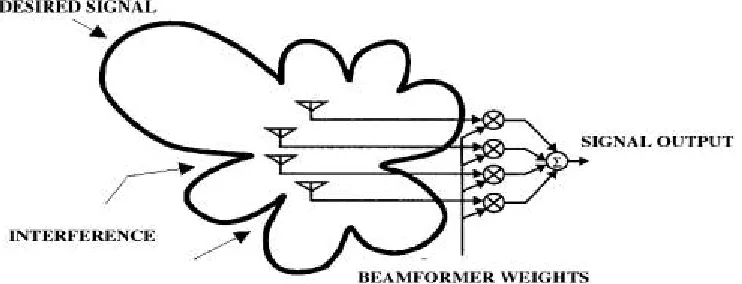
In Fig.1 the outputs of the individual sensors are linearly combined after being scaled with the corresponding weights optimizing the antenna array to have maximum gain in the direction of desired signal and nulls in the direction of interferers. For beamformer the output at any time n, y(n) is given by a linear combination of the data at M antennas, with x(n) being the input vector and w(n) being the weight vector [5].
Fig. 1Display Beamforming
III.LINEAR ANTENNA ARRAY
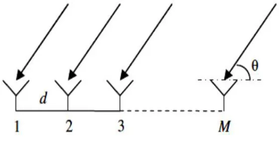
It illustrates an antenna which built up of numerous single radiators. During constructive interference, the radiation fields overlap and forms a common antenna diagram. As an individual radiator, the majority of designs of antennas could be utilized. Single elements are aligned commonly in a line and directing in alike direction, in a one-dimensional antenna array.Fig. 2 indicates a linear spaced equally antenna array, which comprises of N single elements. The d demonstrates space between the neighboring antenna elements. At every reception elements, the delay of the following time τn exists for an occurrence of electromagnetic wave at an angle θs:
Tn
=
∗
sin(
Ѳ
)
(1)
Where:
n = ..., the number of every single element comparative to the antenna center.
Fig. 2 Linear antenna array
It is essentially significant to guarantee that the spacing of element is smaller than half a wavelength when designing an antenna array. The aliasing impact resulted in some side lobes if this restraint is not fulfilled. This could become considerably bigger in amplitude, and oncoming the level of the main lobe. They named grating lobes, as well as they are closely alike copies of the chief beam. Grating lobes are a distinctive circumstance of side lobes. In this circumstance, the sidelobes ought to be regarded the whole lobes lying between the first grating lobe and the main lobe. Because grating lobes have bigger amplitudes in comparison to the most of the other side lobes, it is theoretically advantageous to differentiate between grating lobes and sidelobes. They make the antenna highly susceptible for noise from nuisance signals originating from directions far away from the transmission source, for antennas utilized as receivers. sidelobes demonstrate susceptibility of security, as an unplanned receiver might pick up the classified communication for transmit antennas communicating categorized data. When this is taken into consideration, the maximum distance between two neighboring elements is d ∼λ/2 and the delay of time for every single element might be demonstrated by:
Tn=
∗ ( ) (2)
Where:
plane wave with sn(t) = s0(t − τn), which imposes at an angle θs on a linear antenna array with N receiving elements, every single element alienated from its immediate adjacent element by d.
When the received signal displays a tiny bandwidth B which conform in the association
≪( ) (3)
( ) = 0( )∗ ∗ ∗ = 0( )∗ ∗ (4)
As:
f0 represents the center frequency. The phase shift of every single element relies merely on the incident angle θs and its position in the array because of the equidistant distance between the elements,
∅ = ∗sin( ) (5) ϕn= π n sin(θs) with d = λ/2 (6)
Considering this circumstance, for the received signal for a uni- form linear spaced array antenna, the subsequent equation can be written as:
= ( ) (7)
The factor has been introduced for normalizing the amplitude. Outlining the whole individuals from a one-dimensional antenna array seeking the direction of θs with an incident signal S0 is:
( ) =∑ ( )∗ 0 (8)
IV.METHODS
One M mobile operators and a single base station with (8)element antenna array were utilized in this investigation. firstly the antenna receives signals from variousoperators and every single element of antenna have occurrence wave at the similar time everyoperator has angle when there are interference sources and d desired signal sources transmitting on same frequency channel at the same time. throughutilizing the subsequent received signal equation, The weight (w)chooses the larger value to steer beam for the user.
( ) = + (Ѳ) ( ) + (Ѳ − ) ( )
As:
a(Ѳ)represents array steering vector signifying the amplitude improvement and the phase shift of the signal. The signal s(t). The output of the beamformer system could be demonstrated as:
V. RESULT AND DISCUSSION
In the fig 1, it shows the graph of time Vs throughput of receiving packet. Throughput is the average rate of successful message delivery over a communication channel.
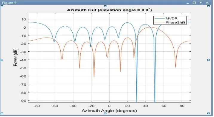
Fig. 3describes Pattern versus azimuth angle with zero elevation angle for MVDR and LCMV beamformer it is obvious that for MVDR, the maximum power is at 10 degree of Zenith however for LCMV, it is about 15 degree of Zenith. this indicate about 5-degree shift.
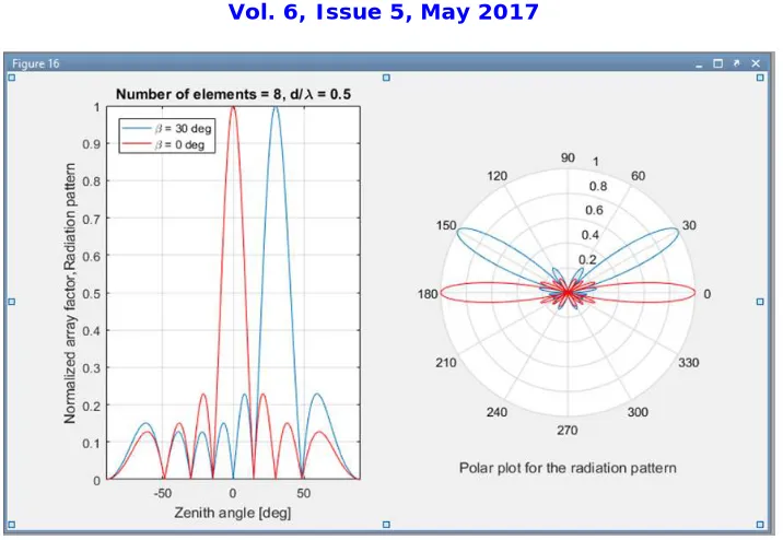
Fig .5displays the 8 elements at two elevation (0 and 30 degree)
In Fig 5, explains Normalized radiation pattern versus Zenith angle and the polar radiation pattern when the ratio between distance and wavelength is 0.5, number of elements is 8 and two elevation angles 30 degree and 0 degree.
Fig.5 displays Radiation pattern for Tx and Rx with Interference
It describes the radiation pattern for the transmitting and receiving signal with the existence of interference. it is shown that the main lobe is not receiving the interference with the use of proposed work, therefore the system is improved.
VI.CONCLUSION
All the energy, in this technique, is steered in one point by pointing a transmitting element in an antenna array for reaching a desired receiver in a given direction.
this examination employed the beamforming system for the next generation wireless communication systems. Improving the coverage and minizine the interference were the purposes of this study. To accomplish these purposes, various beamforming techniques such as Minimum variance distortionless response (MVDR), phase shifter beamforming and linear constraint minimum variance (LCMV) were employed. It is discovered that the (MVDR) had better performance comparing to the other techniques. Moreover, the results of the simulation indicate applying the number of elements (8) the ratio between the distance and wave length 0.5 and 10 GHz has enhanced the coverage and minimized the interference. Therefore, its proved that the beamforming is beneficial for next generation mobile system and have a important role in next generation of mobile networks. Thus, it can be stated that Beamforming is a decent candidate which accomplishes user requirements with effective spectrum application.
REFERENCES
[1] K. A. KUMBAR, “Adaptive beamforming smart antenna for wireless communication system,” International Research Journal of Engineering and Technology (IRJET), vol. 2,Issue .3,pp. 2395-0072, 2015
[2] PARRÓN GRANADOS, J, & KHALIL, D., HASSAN, S.” Design and construction of a 4G mobile network antenna”. 2015.
[3] P. K. NAYAK et al,” Performance Analysis of Smart Antenna Using Beam Forming Techniques”Advance in Electronic and Electric Engineering, vol.4, no.2, pp.201-206, 2014
[4] SAHU, R., MOHAN, R. & SHARMA, S.” Evaluation of Adaptive Beam Forming Algorithm of Smart Antenna”. International Journal of Scientific Engineering and Technology, vol.2, no.10, pp.1031-1037, 2013
[5] P. K. NAYAK,” Performance Analysis of Smart Antenna Using Beam Forming Techniques”. 2014 [6] M. VAVRDA, “Digital beamforming in wireless communications”. Brno University of Technology,2011
[7] S.K. Tiong,S. P. Koh and Balasem. S.S.” Beamforming Algorithms Techniqueby Using MVDR and LCMV”.World Applied Programming,