A Study on Facts Device and STATCOM
Mathematical Modeling
Pooja Yadav1, Dr. Raj Kumar2
M.Tech Student, Department of EE, Mata Rajkaur Institute of Engineering, Rewari, Haryana, India1 Director, Mata Rajkaur Institute of Engineering, Rewari, Haryana, India2
ABSTRACT: Since the emerge of Power electronics technology more and more semiconductor devices with ratings from few tens to Hundreds of Giga watts are designed and providing good efficiency at cheap price with high switching speed and less power loss. Semiconductor devices that falls in Power electronics are generally named as FACTS. The purpose of designing FACTS controllers is to have the capability of enhancing transmission system control, reliability, and operation. These devices control the electrical parameters like systems voltage, current, impedance, phase angle and damping of oscillations. Since 1970 there are various Shunt Flexible AC Transmission Systems (FACTS) devices have been utilized for the improvement of its dynamic performance. Few of those devices will be discussed in this paper to make a good understanding for my upcoming design of DSTATCOM utilizing SVPWM. This paper will discuss the basics principle of FACTs devices and mathematical modelling of the STATCOM. This paper also gives a brief introduction to Static VAR Compensator. Various application related to real world implementation has been presented and also depicts how the Facts devices takes over mechanical switching devices.
KEYWORDS: STATCOM, FACTS, SVAR.
I.INTRODUCTION
FACTS devices come like a revolution in the power transmission and distribution industry. The FACTS devices used to control the various important parameter of electrical power signal at high speed with less mechanical efforts. Their presence in the electrical energy transmission system has significantly affected the operation of traditional distance schemes when either series or shunt connected FACTS devices introduce new dynamic controls into the power systems. This paper presents STATCOM, a shunt connected FACTS device, and its modeling technology. Some standard Definition for FACTS devices and controller are given below:
Flexible AC Transmission System (FACTS) Alternating current transmission systems incorporating power electronic-based and other static controllers to enhance controllability and increase power transfer capability.
FACTS Controller; a power electronic-based system and other static equipment that provides control of one or more AC transmission system parameters.
In general, FACTS Controllers can be divided into four categories according to the way they are connected to the power system [2]:
• Series Controllers • Shunt Controllers
• Combined series-series Controllers • Combined series-shunt Controllers.
Characteristics of these four FACTS Controllers in applications are listed below:
Series Controllers:
The series controllers injects voltage in series with the connected transmission line [2]. For easy understanding, a Series Controller works as variable impedance multiplied by the current flowing through it, so it can represent an injected series voltage in the line.
Shunt Controllers:
with the system line voltage, the shunt controller only supplies or consumes variable reactive power. Any other phase relationships will involve real power exchange.
Combined series-series Controllers:
These could be either a combination of separate series controllers or a unified controller [2]. A combination of separate series controllers is controlled in a multiline transmission system in a coordinated manner. While as a part of a unified controller, series controllers can provide independent reactive power compensation for each line, and transfer real power among the lines via the power link.
Combined series-shunt Controllers:
This type of controller could be a combination of separate shunt and series controllers, which are controlled in a coordinated manner, or a Unified Power Flow Controller with series and shunt elements [2]. Combined shunt and series controllers will inject current into the system with the shunt part of the controller, and voltage in series in the line with the series part of the controller. When the shunt and series Controllers are unified, there can be a real power exchange between the series and shunt Controllers via the power link.
II. STATIC VAR COMPENSATOR (SVC)
With the development of power electronics, Flexible AC Transmission System (FACTS) devices like SVCs have been used for dynamic reactive power compensation [1], [4], [5]. These devices are static in nature and do not have any rotating parts like synchronous condenser. Due to being static in nature and with the use of power electronic switches, SVC gives faster response than synchronous condenser.
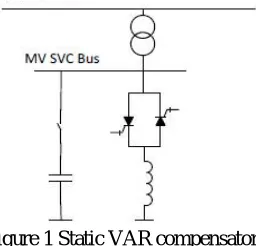
A typical SVC device consists of a capacitor connected with a mechanical switch and an inductor in series with anti parallel connected thyristor switches. The unit is connected to high voltage (HV) line with a transformer in order to lower the voltage rating of thyristor valves [1].
Figure 1 Static VAR compensator
To supply reactive power, capacitor is connected with the grid; and for dynamic support thyristors valves are operated to provide variable inductive power. Thus with combined operation SVC works as a variable capacitor or a variable inductor.
Due to switching devices, SVC generates harmonics. Thus filters need to be installed to bypass them to ground [1]. In SVC, thyristors are used as switching devices which provides only one degree of freedom. With thyristors, only their turn ON event can be controlled, but not turn-OFF. It switches OFF naturally when current becomes zero through the switch. Therefore, SVC has typical response time of 3-5 electrical cycles (50 -90 ms) [1], [3], [6]. This is faster when compared to the synchronous condenser, but SVC requires physical inductors and capacitors which require a large space and other protection strategies [1].
III.STATIC SYNCHRONOUS COMPENSATOR (STATCOM)
STATCOM uses IGBT, IGCT or GTO as switching devices. In these switches, both switching ON and switching OFF events can be controlled. So this gives two degrees of freedom compared to one degree of freedom given by thyristors in SVCs. This makes it faster and more effectively controllable.
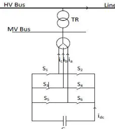
Figure 2 Static synchronous compensator (STATCOM)
Figure 2 presents a typical STATCOM connected to a medium voltage (MV) bus. A transformer ‘TR’ is used to lower down the voltage from high voltage (HV) bus so that lower voltage rating switches (S1-S6) can be utilized. It has a capacitor at dc-link to provide the path for current [1]. Smoothing reactor / transformer is used to reduce the harmonic content in voltage. The operating time of STATCOM is 15-30 ms, which is very fast among all the FACTS devices mentioned above. Main reason for its fast response is the absence of any rotating mass and the use of IGBTs, IGCTs or GTOs as switching device. This explains the name, STATic synchronous COMpensator (STATCOM).
In balanced electrical system, primary STATCOM controller consists of an inner current control loop and outer control loop. Furthermore, the controller is modified to include the effect of different configurations of coupling transformer. For STATCOM operation in unbalanced electrical system, a negative sequence controller is developed that uses Fortescue decomposition technique to obtain sequence components. Separation of positive and negative sequence components is presented without using a 2ndharmonic notch filter.
Successively, a supplementary controller is developed for load compensation, which includes power factor correction and compensation of negative sequence load current. A temporary overvoltage (TOV) regulator is also developed to regulate the overvoltage in case of asymmetric faults. A voltage balancing controller, together with voltage regulator is designed and block diagrams of complete controllers are also presented.
IV.MODELING OF STATCOM CONNECTED TO A GRID
Figure 3 illustrates a schematic diagram of STATCOM connected to power system. The network consists of a load connected to grid through a transmission line. STATCOM, a VSI (Voltage sourced inverter) with a capacitor in DC link, is connected to provide reactive power support to load. VSI is constituted of electrical switches (S1-S6) such as IGBTs or GTOs and series inductance (or a transformer). In this figure, represents the switching losses in the inverter and power loss in capacitor, represents inverter and transformer conduction losses and is the leakage reactance of transformer or smoothing reactor or a combination of both. , and are the phase currents flowing out of STATCOM in the Figure 3. PCC voltage and VSI output voltage are denoted by ‘ ’ and ‘e’ respectively. The output phase voltages of VSI are given by , and . The phase voltages at the PCC are denoted as , and . Then:
− = +
− = +
− = +
Combining all three phases:
= ⎣ ⎢ ⎢ ⎢ ⎢ ⎢
⎡− 0 0
0 − 0
0 0 −
⎦ ⎥ ⎥ ⎥ ⎥ ⎥ ⎤ + 1 − − −
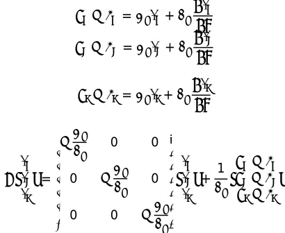
where, is operator for . Applying transformation from abc reference frame to synchronously rotating dq reference frame:
= −− − + −−
Subscript ‘d’ and ‘q’ indicate electrical quantities in d-axis and q-axis reference frame respectively. There are two basic type of voltage source inverters [8]:
1) Inverter Type I 2) Inverter Type II
Inverter Type I is of primary interest for distribution utilities needing wider range of power control. With this type of inverter, capacitor voltage can be kept sufficiently high for independent control of and . Inverter Type II is primarily used with transmission lines and have limited decoupled control on power flow [8].
V. APPLICATION OF STATCOM
REFERENCES
[1]R. M. Mathur and R.K. Varma, “Thyristor based FACTS controllers for Electrical transmission systems” IEEE press 2002.
[2]N G Hingorani and L Gyugyi. Understanding FACTS: Concepts and Technology of Flexible AC Transmission Systems, IEEE Press, 2000, Chapter 5 [3] G. Gueth, P. Enstedt, A. Rey and R. W. Menzies, “Individual phase control of a static compensator for load compensation and voltage balancing and regulation”, IEEE Transactions on Power Systems, vol. 2, no. 4, pp. 898-905. 1987.
[4] http://www.abb.ca/
[5] N. G. Hingorani and L. Gyugyi, “Understanding FACTS: Concepts and Technology of Flexible AC transmission system” IEEE press 2000.
[6] Singh, B.; Murthy, S.S.; Gupta, S., "A Stand-Alone Generating System Using Self-Excited Induction Generators in the Extraction of Petroleum Products," in Proc. IEEE Transactions on Industry Applications, vol. 46, no. 1, pp.94-101, Jan.-Feb. 2010.
[7]http://www.energy.siemens.com/us/en/power-transmission/hvdc/hvdc-plus/modularmultilevel-converter.htm