A Preliminary Design of Pre-service Test Platform for HTR-10GT
Ping Ye1, Liang Zhu2, Jie Wang3, and Suyuan Yu4
1 Engineer, Institute of Nuclear and New Energy Technology, Tsinghua University, Beijing, China
2Assistant Professor, Institute of Nuclear and New Energy Technology, Tsinghua University, Beijing,
China
3, 4 Professor, Institute of Nuclear and New Energy Technology, Tsinghua University, Beijing, China
ABSTRACT
Pre-service test is a key verification procedure for design and construction of the 10 MW high temperature gas-cooled reactor coupled with helium turbine (HTR-10GT) project. It is very important to ensure the mechanical performance and reliability of the turbo-compressor system before it connects with reactor.
Thus, a pre-service test platform was designed to verify the system technical feasibility, such as dynamic characteristics of rotor which was supported by active magnetic bearings and aerodynamic characteristics of turbo-compressor. On this test platform, basic configuration and key structure parameters were given the same or basically same as those in HTR-10GT project.
The most key components, such as motor, gear box, helium turbine, low pressure compressor and high pressure compressor, were integrally assembled vertical and biaxial in a pressure vessel. The motor rotor was on one axis and the turbo-compressor rotor was on the other. The turbo-compressor rotor was supported by two radial magnetic bearings along with an axial magnetic bearing. The design load capacity of the axial magnetic bearing and the radial magnetic bearing was 9.8kN and 1.96kN, with a clearance of 0.7mm and 0.6mm, respectively. The rated rotation speed was 15,000 rpm for turbo-compressor rotor, and 3,000 rpm for motor rotor. Analysis showed that the design would satisfy tests’ requirements. General debugging, operating tests and related studies were also considered.
.
INTRODUCTION
For recent years, reactor coupled with helium turbine was estimated as a potential developing technology direction of high temperature gas cooled reactor (Ding, 2009). Researches were conducted in projects such as GT-MHR(Baxi, 2008), PBMR(Venter, 2005) , VHTR(El-Genk, 2009) and so on.
Based on the success of the 10MW high temperature gas-cooled reactor (HTR-10) construction and experimental results (Wu, 2002), the 10 MW high temperature gas-cooled reactor coupled with helium turbine (HTR-10GT) project was developed in the Institute of Nuclear and New Energy Technology. The purpose was to use helium turbine instead of steam turbine to take full advantage of gas-cooled reactor’s high outlet temperature and get higher power generation cycle efficiency. The main purpose of HTR-10GT was to explore the characteristics of helium turbine power generation system.
After simulation experiments for the helium turbine was successfully held (Zhu, 2012), a pre-service test platform was designed to verify the technical feasibility of PCU, such as dynamic characteristics of rotor which was supported by AMBs and aerodynamic characteristics of turbo-compressor. On this test platform, the basic configuration and key structure parameters were the same or basically same as those in HTR-10GT project, and the thermal parameters followed similarity principle. All pre-service tests would be carried out on this platform. These tests would be divided into individual equipment tests and whole scale overall no-loading tests, in particular as tests of motor, tests of motor and gear box, tests of turbo-compressor, tests of turbo-compressor and active magnetic bearings rotor system. These tests would confirm the key technology of system operability, assembling, adjustment, control and parameters measurement, and provide basic references for the development of HTR-10GT.
OVERALL LAYOUT
The power conversion system of platform was assembled vertical and biaxial as same as HTR-10GT. As there was no power generation requirement, a motor was used instead of generator. The motor rotor was on one axis and the turbo-compressor rotor was on the other. The axes were connected by a gear box and two couplers. These key components were all located in a pressure vessel. From top to bottom, there were motor, low-speed side coupler, gear box, high-speed side coupler, turbo-compressor rotor and rotor support frame with magnetic bearings, respectively. The advantages of this kind of configuration were simple structure, easy control and strong avoidance ability of load rejection.
The motor was an inverter motor and it was connected with the gear box by the low-speed side coupler. The rated speed of motor was 3,000 rpm and highest speed was 3,600 rpm. The nominal power is 110kW.
The gear box was developed by INET. A gear ratio of 1:5 was used, and the high-speed side connected to the turbo-compressor rotor. With 2500kW as nominal power and 3,000rpm as rated output speed, the rated speed of turbo-compressor rotor was 15,000 rpm and highest speed was 18,000 rpm. An oil station was set to cool the gear box.
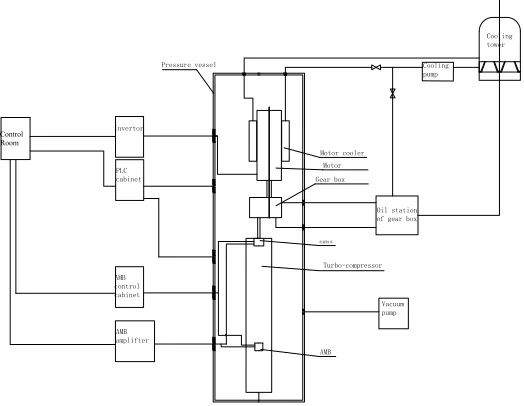
There were also control system, cooling system and vacuum system which located outside the pressure vessel. As air was used as the test working fluid on this platform for its lower price than helium, dynamic similarity principle was applied to simulate the helium parameters with air. For the limited motor capacity, vacuum system was used to make the no-load rotation possible. The vacuum degree was around 0.15 bars. A cooling tower was used to cool the motor and the gear box.
Figure 1 showed the system diagram of the test platform.
Cooling pump Cooling tower Motor cooler Motor Oil station of gear box Gear box Turbo-compressor Invertor Control Room 电磁轴承 AMB AMB amplifier Vacuum pump Pressure vessel AMB control cabinet PLC cabinet
PRESSURE VESSELAND MAIN STRUCTURE MATERIALS DESIGN
Most key components were located in the pressure vessel for integral assembling and safety. There should be enough strength and stability for the vessel to get Structural integrity in tests. The vessel design was same as vessel in HTR-10GT project to save cost. After the tests, this vessel should also be used for HTR-10GT. Its main design parameters were3.5MPa and 350℃.
The vessel would be evacuated to easily drive turbo-compressor rotor and joined by three flanges. It was divided into two chambers. The motor, gear box and couplers were assembled in the upper chamber, and turbo-compressor container was in the lower chamber. The turbo-compressor unit was assembled in the container. Chambers were sealed by buffer seal. Electrical penetration assemblies were used to connect with instrument, control and electrical systems. The inlet and outlet of cooling water system for motor and gearbox were also designed on the upper chamber.
The main body of pressure vessel was divided into three parts. The bottom part was consisted of straight cylinder shell and ellipsoidal head which contained the turbo-compressor container. The middle part was a cylinder shell which contained the motor and gear box. The top part was consisted of a flange and ellipsoidal head. FEA result showed that there was enough strength and stability of the pressure vessel.
There was a small barrel located between the master cylinder housing flanges of the bottom cylindrical shell. The central of basket is the locating base of gear box and turbo-compressor container.
The turbo-compressor container located in the middle of the bottom cylindrical shell of pressure vessel. Its first order inherent frequency was 217.1Hz, longitudinal length extensional vibration and would not be stimulated. The second order inherent frequency was 304.3Hz, radial pendular oscillation and higher than rated frequency 250Hz. Results showed that there was enough strength and stability of the container.
Figure 2 showed the detail configuration in the pressure vessel.
TURBO-COMPRESSORSYSTEM DESIGN
The turbo-compressor system was vertically assembled. From top to bottom of the rotor, there were bearing pedestal, axial magnetic bearing, upper radical magnetic bearing, turbine, high pressure compressor, low pressure compressor and lower radical magnetic bearings.
The bearing pedestal was the support and fixed point of whole compressor unit. The turbo-compressor could expanse freely downwards. The stator was fixed into the bearing pedestal by the exhaust casing. In order to avoid using over-length shaft, the pressure ratio was chosen as 2.42. Figure 3 showed the structure of turbo-compressor rotor and the rotor casing.
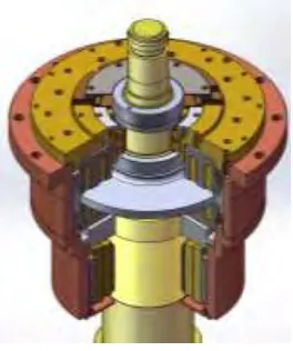
AMBs were one of the main challenges of HTR-10GT. The design load capacity of the axial magnetic bearing and the radial magnetic bearing was 9.8kN and 1.96kN, with a clearance of 0.7mm and 0.6mm, respectively. The clearance of axial and radial auxiliary bearings was 0.15mm and 0.30mm.
Figure 4 and Figure 5 showed the preliminary design of AMBs near turbine side and compressor side.
Parameters of turbo-compressor rotor were shown in Table 1. Thermal expansion was 9.99mm for the stator and 5.37 mm for the rotor. Calculated critical speed of rotor was shown in Table 2.
AMB Gear box
Turbine
AMB Motor Cooler Motor
High pressure compressor
Low pressure compressor
Figure 2. Whole layout in pressure vessel Figure 3.Structure of turbo-compressor rotor
Figure 4. Design of AMBs near turbine side Figure 5. Design of AMBs near compressor side
Table 1: Parameters of turbo-compressor rotor
Parameters Length (mm) Mass (kg) (mm)(from bottom) Gravity position Moment of inertia (kg•mm2)
Value 3,568 645 1,715 I1=5.42×10⁶
Table 2: Critical speed of turbo-compressor rotor
Mode Precession movement Pendular First bending Second bending Third bending
Critical
speed(rpm) 1,030 1,958 4,179 11,483 18,120
PRE-SERVICE TESTS DESIGN
To verify the mechanical performance of whole system, we gave a list of pre-service tests. These tests included tests for individual components and for whole scale system. All tests were designed following the similar principles.
For individual components, we paid lots of attention on the characteristics of AMBs, turbo-compressor and the rotor. Tests for AMBs included static tests, dynamic tests and auxiliary bearing tests. Tests for rotor included rotor dynamics test such as a second-order bending critical test. For the turbo-compressor, tests included aerodynamic tests, strength tests, vibration tests and noise tests.
For the no-loading whole scale overall system tests, the rotation speed of turbo-compressor would be from zero to 120% rated speed. Detailed tests were designed and the key components collaboration status, the reliability of control and instrument, electrical system, the assembly procedure would be validated.
CONCLUSION
In this paper, we described the preliminary design for the pre-service test platform for HTR-10GT, which would be used to study the overall performance of whole system especially the turbo-compressor rotor supported by AMBs.
In this platform, motor, gear box, turbo-compressor rotor, control system, cooling system and vacuum system were included. The most key components were all integrally assembled vertical and biaxial in a pressure vessel the same as HTR-10GT energy conversion system. The pressure vessel and main structure materials, the turbo-compressor system were designed and a list of pre-tests were designed. Analysis showed that the design would satisfy tests’ requirements. On this basis, we would take further study on the platform design and tests to ensure the HTR-10GT system reliability.
ACKNOWLEDGMENTS
This work is supported by the National Program of The Tenth-Five-Year Plan Key Project (Grant No.2005AA511010) and the National S&T Major Project(Grant No. ZX06901).
REFERENCES
Ding, M. (2009). “Study on Dynamic Characteristics and Control Methods of HTGR Brayton Cycle,” PhD thesis, Tsinghua University, Beijing, China.
Baxi, C.B., Shenoy, A., Kostin, V.I., Kodochigov, N.G., Vasyaev, A.V., Belov, S.E., Golovko, V.F. (2008). “ Evaluation of alternate power conversion unit designs for the GT-MHR, ”. Nuclear Engineering and Design, 238(11), 2995-3001.
El-Genk, M. S. , Tournier, J. M.(2009). “Performance analyses of VHTR plants with direct and indirect closed Brayton cycles and different working fluids,” Progress in Nuclear Energy,51(3), 556-572. Wu, Z. X., Lin, D. C. and Zhong, D. X. (2002). “The Design Features of The HTR-10,” Nuclear
Engineering and Design, 218( 1-3) : 25-32.
Zhu, L., Shi, Z. G. (2012). “A Design of Simulation Experiment System for The Helium Turbine, ”Proceedings of the 20th International Conference on Nuclear Engineering, July 30-August
3, 2012, Anaheim, California, USA.