Transactions,SMiRT-23
Manchester, United Kingdom - August 10-14, 2015
Division IX, Paper ID 612 (inc. assigned division number from I to X)
1
A Review of Suitability for PWHT Exemption Requirements
in the Aspect of Residual Stresses and Microstructures
Seung-Gun Lee1and Young-ho Son2
1 Korea Institute of Materials Science (KIMS), Korea 2 Korea Institute of Materials Science (KIMS), Korea
ABSTRACT
PWHT (Post Weld Heat Treatment) for ferritic steels is necessary according to code requirements, such as ASME Section III, NX-4620. Its application is known as relaxing residual stresses and improving resistance to brittle fracture, but the exact reason and the technical background are not clarified. There are code requirements for permitting as-welded condition without PWHT. According to ASME Section III, NX-4622.7, there suggests exemption requirements for PWHT. However, the technical background of the PWHT exemption requirement is also not cleared, so when the nominal material thickness is located around the boundary of PWHT exemption requirements, it is hard to decide whether PWHT is necessary or not.
In this study, the effect of PWHT on residual stress and microstructures in welded pipe was evaluated using sequentially coupled 2D thermal and mechanical analysis by FE software, SYWELD. Moreover, the change of mechanical properties with PWHT was also investigated by testing the welded pipe specimen. Finally, the background and suitability of PWHT exemption requirements in ASME Section III were reviewed.
1. INTRODUCTION
During the welding process, the weld area is heated up sharply relative to the surrounding area. The heat expansion of the weld area is restricted by surrounding area, so thermal stresses partly exceed the yield limit. Therefore, the weld area shows tensile residual stress while the surrounding area shows compressive residual stress after cooling down. In addition to heat expansion of the weld, the welding involves the change of microstructures in ferritic steels with variation of cooling rate, which produces volumetric change due to solid state phase transformation and finally creates residual stresses.
Usually, welding produces tensile axial and hoop stresses in the inner or outer surface of piping component and if the tensile residual stresses occurs inner surface of the piping component, it can initiate surface flaws with combination of operating conditions. Through-wall residual stress distribution is important in the aspect of surface flaw growth. It can exhibit rather different forms at a weld, depending on piping geometry such as piping thickness or the ratio of radius to thickness. The welding residual stresses can be reduced by heating the component to above recrystallization temperature, which is called PWHT. It can also improve the resistance of brittle fracture and the risk of distortion. The elastic modulus and the yield limit are substantially reduced at this temperature and creep processes occur to a greater extent in which creep strain development or creep-induced stress relaxation occurs [1].
2
Additionally, ASME Section III, NX-4622.7 suggested exemptions to mandatory requirements for PWHT based on the P Numbers as assigned by ASME Section IX, nominal material thickness, alloy contents, and preheat temperature. But the technical background of exemption requirement is also not cleared, so when the thickness of the component is located around the boundary of PWHT exemption requirements, it is hard to decide whether PWHT is necessary or not.
The objective of this study is to review the exemption requirements for PWHT in the several construction codes such as ASME B31.1[3], B31.3[4], Section I and Section III codes and identify how the residual stress is created and reduced according to welding and PWHT for the welded pipe. This is done performing FEA (Finite Element Analysis) using commercial FE software, SYSWELD and mechanical tests for welded pipe specimen, and finally the technical background and suitability of PWHT exemption requirements in ASME Section III were reviewed and suggested.
2. PWHT EXEMPTION REQUIREMENTS IN ASME CODES
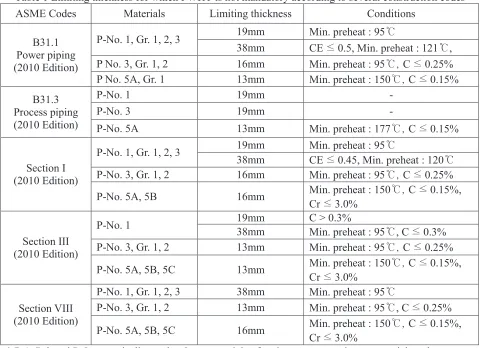
In order to guess the technical background on PWHT exemption, PWHT exemption requirements in several ASME codes are reviewed. ASME codes suggested that PWHT is not mandatory when the nominal material thickness is not more than the thickness in Table 1.
Table 1 Limiting thickness for which PWHT is not mandatory according to several construction codes
ASME Codes Materials Limiting thickness Conditions
B31.1 Power piping (2010 Edition)
P-No. 1, Gr. 1, 2, 3 19mm Min. preheat : 95ଇ
38mm CE ˺ 0.5, Min. preheat : 121ଇ, P No. 3, Gr. 1, 2 16mm Min. preheat : 95ଇSGC ˺ 0.25% P No. 5A, Gr. 1 13mm Min. preheat : 150ଇSGC ˺ 0.15%
B31.3 Process piping (2010 Edition)
P-No. 1 19mm -
P-No. 3 19mm -
P-No. 5A 13mm Min. preheat : 177ଇSGC ˺ 0.15%
Section I (2010 Edition)
P-No. 1, Gr. 1, 2, 3 19mm Min. preheat : 95ଇ
38mm CE ˺ 0.45, Min. preheat : 120ଇ
P-No. 3, Gr. 1, 2 16mm Min. preheat : 95ଇSGC ˺ 0.25%
P-No. 5A, 5B 16mm Min. preheat : 150ଇSGC ˺ 0.15%, Cr ˺ 3.0%
Section III (2010 Edition)
P-No. 1 19mm C > 0.3%
38mm Min. preheat : 95ଇ, C ˺ 0.3% P-No. 3, Gr. 1, 2 13mm Min. preheat : 95ଇSGC ˺ 0.25%
P-No. 5A, 5B, 5C 13mm Min. preheat : 150ଇSGC ˺ 0.15%, Cr ˺ 3.0%
Section VIII (2010 Edition)
P-No. 1, Gr. 1, 2, 3 38mm Min. preheat : 95ଇ
P-No. 3, Gr. 1, 2 13mm Min. preheat : 95ଇ, C ˺ 0.25%
P-No. 5A, 5B, 5C 16mm Min. preheat : 150ଇSGC ˺ 0.15%, Cr ˺ 3.0%
* P-1, P-3 and P-5 are typically used as base materials of main components in commercial nuclear power plants in Korea
** CE (Carbon Equivalent) ,
23rd Conference on Structural Mechanics in Reactor Technology Manchester, United Kingdom - August 10-14, 2015 Division IX (include assigned division number from I to X)
3
There was some variation between codes as shown in Table 1, and the reason for this has been not known. There are the general trends that the permitted thicknesses without PWHT is increased with increasing preheat temperature together with reductions in maximum carbon level, and the permitted thickness is decreased with increasing alloy content of steels. Most manufacturers are trying to avoid PWHT based on the Table 1 because there is an economic incentive to avoid PWHT.
3. FINITE ELEMENT ANALYSIS
3.1 FINITE ELEMENT MODEL
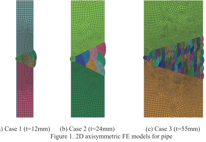
Three different thicknesses of pipes that made of SA106 Gr.B are considered for computational simulation, which consists of 12mm, 24mm, and 55mm thickness. SA106 Gr.B is categorized as P number 1 material in ASME Section IX. A schematic of pipe models are shown in Fig. 1. According to the ASME Section III requirements suggested in Table 1, PWHT for 12mm and 24mm thickness of pipes is not mandatory, but PWHT for 55mm thickness of pipe is mandatory.
(a) Case 1 (t=12mm) (b) Case 2 (t=24mm) (c) Case 3 (t=55mm) Figure 1. 2D axisymmetric FE models for pipe
3.2 MATERIAL PROPERTIES
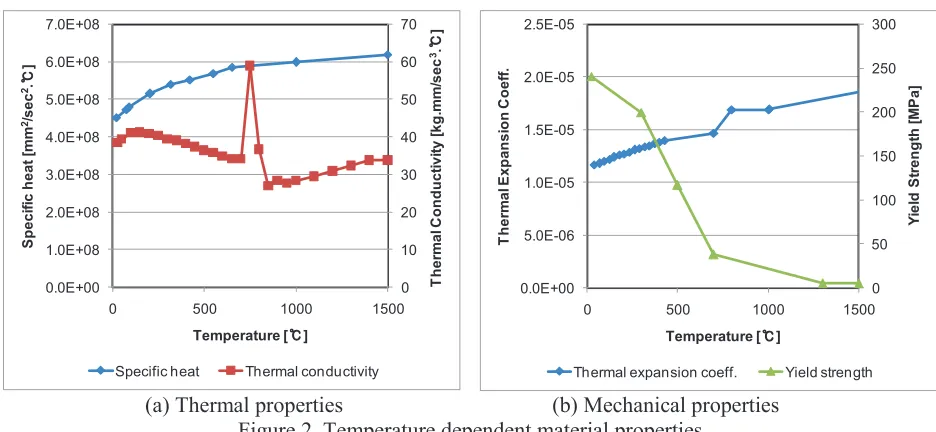
The materials for pipe and butt weld are SA106 Gr. B and E71T-1 respectively, which are commonly used as piping materials in commercial nuclear power plants in Korea. Temperature dependent values of specific heat, thermal conductivity, thermal expansion coefficient and yield strength used in FEA were can be found in Fig. 2. Density was assumed to be 7.83E-06 kg/mm3 and Poisson’s ratio to be 0.29, both independent of temperature.
3.3 WELDING CONDITIONS
4
0 50 100 150 200 250 300 0.0E+00 5.0E-06 1.0E-05 1.5E-05 2.0E-05 2.5E-050 500 1000 1500
Y ie ld S tr e n g th [ M P a ] T h e rm a l E x p a n s io n C o e ff . Temperature []
Thermal expansion coeff. Yield strength 0 10 20 30 40 50 60 70 0.0E+00 1.0E+08 2.0E+08 3.0E+08 4.0E+08 5.0E+08 6.0E+08 7.0E+08
0 500 1000 1500
T h e rm a l C o n d u c ti v it y [ k g .m m /s e c
3.
] S p e c if ic h e a t [m m 2/s e c
2.
]
Temperature []
Specific heat Thermal conductivity
(a) Thermal properties (b) Mechanical properties Figure 2. Temperature dependent material properties
Table 2. Piping geometrical information
Case No. Thickness, mm Radius, mm r/t No. of Beads
1 12 30 2.5 4
2 24 60 2.5 8
3 55 137.5 2.5 73
Table 3. Welding parameters
Case No. Method Current, A Voltage, V Speed, cm/min PWHT, ଇ
1, 2, 3 GTAW (root)
FCAW (others) 180~280 25~35 20~50 615, 1.0hr/in
3.4 WELDING SIMULATION
Welding simulation was performed using SYSWELD version 10.0 [8], a commercial purpose finite element code which can consider phase transformation in steels. The residual stress modelling procedure involves sequentially coupled heat-conduction-based thermal analysis of the welding heat flow and a subsequent incremental thermo-plastic analysis which is dependent on the predicted temperature history. In the first step, transient heat transfer analysis was performed to calculate the temperature distributions of the piping component.
The welding heat input from the welding arc was modelled with double ellipsoid distribution (the Goldak heat source). The power density distribution inside the front and rear quadrant becomes equation (1) [5].
(1)
Where, Q=hVI is net power and a, b, c are configuration parameters
2 2 2
2 2 2
,
3 3 3
,
,
6 3
( , , )
e
f rx y z
a b c
f r
f r
Qf
q x y z
23rd Conference on Structural Mechanics in Reactor Technology Manchester, United Kingdom - August 10-14, 2015 Division IX (include assigned division number from I to X)
5
Convective and radiative heat transfer boundary conditions should be applied to the relevant surfaces of the model, including the weld bead after deposition. Surfaces which are insulated and/or are symmetry planes should be adiabatic (i.e. no heat transfer should take place).
Same finite element mesh as in the heat transfer model was used in the thermo-plastic analysis. Temperature history was read from the heat transfer results, and elasto-plastic deformation due to non-uniform thermal expansion was calculated in the mechanical model. It is assumed that the material has an isotropic strain-hardening behaviour.
3.5 POST WELD HEAT TREATMENT SIMULATION
The relaxation behaviour during the PWHT is numerically modelled based on the viscous plastic model of Leblond that is given at equation (2). It assumes the existence of a domain, defined by a von Mises criterion, inside which elastic and viscous strains can occur.
For
(2)
Where,
(
s
-
c
)
is von Mises function which defines the domain creep strain, K is hardeningcoefficient, n is strain rate sensitivity exponent,
s
is stress tensor, S is stress deviator tensor, andc
is
internal component tensor.
4. FEA RESULTS
4.1 WELDING RESIDUAL STRESS RESULTS
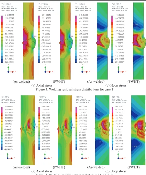
Fig. 3 ~ Fig. 5 show welding residual stress results for case 1, case 2 and case 3 respectively. For case 1, the axial and hoop residual stress distributions exhibit bending type which means that tensile residual stress is formed at the inner surface of piping weld and compressive residual stress is formed at the outer surface of piping weld. This distribution is typical for thin wall piping and it is susceptible for initiation and growth of inner surface flaw. It is needed to apply heat treatment to reduce tensile residual stress at inner surface. For case 2, the inner surface of piping weld is under tension stress and the outer surface of piping weld is also under tension stress. The magnitude of axial weld residual stress in the inner surface of piping weld somewhat decreased compared to case 1, and one of hoop weld residual stress in the inner surface of piping weld decreased greatly. For case 3, as shown in Fig. 5, the axial and hoop residual stress distributions exhibit counter bending type which means that compressive residual stress is formed at the inner surface and tensile residual stress is formed at the outer surface. This kind of stress distribution is helpful to prevent crack initiation and growth, so there is no need to apply heat treatment in the aspect of stress reduction.
The magnitude of residual stresses after PWHT decreased, but the distribution appearance was similar before and after PWHT. Therefore, the final residual stresses after PWHT are somewhat high enough to promote crack growth for case 1 and case 2 if a crack is existed at the inner surface of pipe.
( ) (
)
( )(
)
( )
( ) ( )
( )q
c
q
s
s
c
c
q
e
q
c
c
c
s
q
e
q q&
&
&
&
j
o
r


+
-=
-=
-X
U
U
Y
Z
X X(
)
6
(As-welded) (PWHT) (As-welded) (PWHT) (a) Axial stress (b) Hoop stress
Figure 3. Welding residual stress distributions for case 1
(As-welded) (PWHT) (As-welded) (PWHT) (a) Axial stress (b) Hoop stress
23rd Conference on Structural Mechanics in Reactor Technology Manchester, United Kingdom - August 10-14, 2015 Division IX (include assigned division number from I to X)
7
(As-welded) (PWHT) (As-welded) (PWHT) (a) Axial (b) Hoop
Figure 5. Welding residual stress distributions for case 3
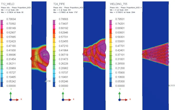
4.2 PHASE PROPORTIONS AFTER WELDING
As the material cools during welding, microstructures in carbon steels are forced to change from one structure to another - these are called phase transformations. The microstructures of carbon steels include not only the crystalline structure but also various metallic carbides or compounds in different arrangements. Bainite is typical microstructures in the HAZ (Heat Affected Zone) of SA106 Gr.B steel. Phase proportions in weld and HAZ after welding and PWHT can be calculated using SYSWELD. As shown in Figure 6, the greater part of microstructures in weld and HAZ consisted of bainite. There is no change of phase proportions after PWHT because PWHT temperature is below Ac1 transformation temperature.
8
5. EXPERIMENTAL RESULTS
5.1 PRODUCTION OF WELDED PIPE SPECIMEN
In order to find out the change of microstructures and mechanical properties in HAZ, welded pipe specimen was prepared as shown in Figure 7. The chemical composition of SA106 Gr.B used in this study is given in Table 4. The thickness of pipe is 24mm, and the outer diameter is 355mm, which is mandatory for PWHT according to ASME Section III code. The welding condition for pipe is shown in Table 3. After finishing the welding, two specimens were obtained from the weld, which included base metal and weld. One specimen was used as it is, and the other specimen was heat treated at 615ଇ for 75min.
Table 4. Chemical composition of the steel
Steel C Si Mn P S Cu Cr Ni Mo
SA106 Gr.B 0.2 0.24 0.97 0.012 0.003 0.01 0.04 0.02 0.01
Figure 7. Production of welded pipe
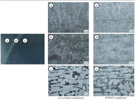
5.2 MICROSTRUCTURE OBSERVATION
Microstructures for weld, HAZ, and base metal were observed using optical microscopy after etching with 2% nital. Optical micrographs of the specimen are shown in Figure 8. As shown in the figure, the microstructure of weld and HAZ consisted of ferrite (white) and pearlite (black), which can be called bainite that has been known as not hard as martensite but can be much tougher. There are no significant differences visibly between as-welded and PWHT condition.
5.3 MECHNICAL PROPERTIES TEST
Vickers hardness and instrumented indentation tests were performed to measure the mechanical properties in weld, HAZ, and base metal. For these tests, specimens were etched with 2% nital to reveal the boundary line of weld, HAZ, and base metal. The hardness test results represent the average of 4 measurements for each area, and instrumented indentation test results represent the average of 3 measurements for each area.
The results of the Vickers hardness tests are shown in Figure 9 (a). The hardness of weld, HAZ, and base metal at as-welded condition is 215Hv, 197Hv, and 156Hv respectively. After PWHT, the hardness values of weld and HAZ were decreased to 168Hv and 172Hv respectively. While the hardness value of base metal was slightly increased to 163Hv. The results of the instrumented indentation test are shown in Figure 9 (b), and they are similar trends as hardness test results. The yield and tensile strength values of weld and HAZ were decreased, and those of base metal were increased after PWHT.
23rd Conference on Structural Mechanics in Reactor Technology Manchester, United Kingdom - August 10-14, 2015 Division IX (include assigned division number from I to X)
9
a b c
a a
b b
c c
(As-welded condition) (PWHT condition)
Figure 8. OM micrographs of (a) weld, (b) HAZ, and (c) base metal
0 50 100 150 200 250
Weld HAZ BM
Ha
rdnes
s
[Hv
,
5
0
0
g
f]
As-welded PWHT
0 100 200 300 400 500 600 700 800
Yield Strength Tensile Strength
Str
eng
th
[M
P
a
] Weld@as-welded
Weld@PWHT HAZ@as-welded HAZ@PWHT BM@as-welded BM@PWHT
(a) Average Vickers hardness (b) Average yield and tensile strength Figure 9. Mechanical test results
6. CONCLUSIONS
10
analyses and mechanical tests for welded pipe specimen were performed to identify the effect of PWHT. The results are summarized as follows:
(1) The through thickness residual stresses at weld centerline in thin wall piping (case 1) exhibit bending type, while those in thick wall piping (case 3) exhibit counter bending type.
(2) The magnitude of residual stresses after PWHT decreased, but the distribution appearance was similar before and after PWHT. Therefore, the final residual stresses after PWHT are somewhat high enough to promote crack growth for case 1 and case 2 if a crack is existed at the inner surface of pipe. Therefore, in the aspect of weld residual stresses, exemption of PWHT is not allowed for thin wall pipe.
(3) The microstructure of weld and HAZ consisted of ferrite and pearlite, which can be called bainite that has been known as not hard as martensite but can be much tougher. There are no significant differences visibly between as-welded and PWHT condition. It was also confirmed by the results of FEA that the greater part of microstructures in weld and HAZ consisted of bainite.
(4) The value of hardness and yield/tensile strength at HAZ was decreased after PWHT, but the difference between as-welded and PWHT condition was just about 10%.
(5) PWHT requirements in construction code were presumed to be written based on microstructure changes only. But, it is hard to find that there are significant changes of microstructures and mechanical properties before and after PWHT for P number 1 material.
(6) More investigation for the changes of microstructure and mechanical properties will be needed to identify the effect of PWHT quantitatively.
REFERENCES
[1] Pingsha Dong and J.K.Hong, "Residual stress relief in post-weld heat treatment", 2008 ASME Pressure Vessels and Piping Conference, PVP2008-61210.
[2] ASME Section III, NX, "Rules for Construction of Nuclear Facility Components", ASME, 2010. [3] ASME B31.1, "Power Piping", ASME, 2010.
[4] ASME B31.3, "Process Piping", ASME, 2010.