C A L C U L A T I O N OF E Q U I V A L E N T STATIC LOADS AND ITS A P P L I C A T I O N
W.S. CHOI ~, K.B. PARK l) AND G.J. PARK 2)
1) Korea Atomic Energy Research Institute, Korea
2) Automatic Design Laboratory, College of Engineering, Hanyang University, Seoul, Korea.
A B S T R A C T
All the forces in the real world act dynamically on structures. Since dynamic loads are extremely difficult to handle in analysis and design, static loads are usually utilized with dynamic factors. Static loads are especially exploited well in structural optimization where many analyses are carried out. However, the dynamic factors are not determined logically. Therefore, structural engineers often come up with unreliable solutions. An analytical method based on modal analysis is proposed for the transformation of dynamic loads into equivalent static loads (ESLs). The ESLs are calculated to generate an identical displacement field with that from dynamic loads at a certain time. The process is derived and evaluated mathematically by using the modal analysis. Since the exact solution is extremely expensive, some approximation methods are proposed. Error analyses have been conducted for the approximation methods. Standard examples for structural design are selected and solved by the proposed method. Applications of the method to structural optimization are discussed.
I N T R O D U C T I O N
In the general design of structures, the structures are analyzed by stress analysis. Currently, the finite element method (FEM) seems to be one of the best choices for computational analysis [1,2]. The external forces are given to the finite element analysis as input. In most cases, static analysis is carried out to calculate the status for failure since it is easy to handle. However, dynamic forces are imposed in the real physics. That is, real forces act dynamically. Transient analysis shows real and precise phenomena of structures under dynamic loads. Some researchers have been trying to use transient analysis in the optimization process, which is a popular method for the automatic design of structures [2-5]. However, transient analysis is extremely complicated and expensive [6,7]. Therefore, static loads are generally utilized in the optimization process. Structural optimization seems to succeed for static loads with dynamic factors [8]. The dynamic factors are being determined by ad hoc processes.
Generally, a static load with a dynamic factor is made in the same direction of the dynamic load. A structure vibrates under a dynamic load. Failure conditions can happen when the structure is deformed in the opposite direction of the dynamic load. Therefore, the analysis by a static load with a dynamic factor may not cover all the failure conditions. Instead, some parts of a structure can be designed in the wrong way. Also, the dynamic factors are not determined in a legitimate manner. A dynamic load is transformed to an ESL set. The ESL set is made to generate the identical displacement field with the one from the dynamic load at an arbitrary time [9-11]. The displacement field under the dynamic load can be expressed by the modal analysis in the vibration theory. If the displacement field of the dynamic load is replaced by that of a static load set, a simultaneous equation is constructed with the unknowns for the static loads. The solution of the equation is the ESL set. The transformation is derived mathematically. The exact solution exists. Since the exact solution is difficult to use and extremely expensive, an approximation method is derived for engineering applications. The relationship between the two methods is discussed. Numerical tests are conducted for standard examples. The application of the developed method is discussed in the context of structural optimization.
T R A N S F O R M A T I O N OF D Y N A M I C LOADS INTO E Q U I V A L E N T STATIC LOADS
Using the vibration theory with the finite element method, the dynamic behavior of a structure is expressed by the
SMiRT 16, Washington DC, August 2001
Paper # 1111following differential equations"
M d + K d - f - { 0 . - . 0 f~...fi+,_~0...0} T (1)
where M is the mass matrix, K is the stiffness matrix, f is the vector of external dynamic loads, d is the vector of dynamic displacements, and 1 is the number of nonzero components of the dynamic load vector. Vector z is defined as follows"
d = Qz (2)
where Q = [1.t/1 ltI 2 ltl 3 " " ud N ] and ~u i = { Uli U2i U3i " ' " UNi }T. The matrix Q is a modal matrix and ~pi is the i-th
eigenvector. Substituting Eq. (2) into Eq. (1), Eq. (1) is decoupled as follows"
+ D z - Q T f (3)
where D is the diagonal matrix whose i-th diagonal component is the square of i-th natural frequency co ~. The dynamic displacement of the p-th degree of freedom (DOF) at an arbitrary time ta is defined as:
N
dp (ta) -- Z U p j Z j ( t a ) j=l
(4)
where N is the total DOF. The above process is called transient analysis. Generally, in transient analysis, the summation of Eq. (4) is carried out up to n which is smaller than N. The static analysis with FEM formulation is expressed as:
K x = s (5)
where x is the vector of static displacements and s is the vector o f external static loads. An ESL set, which generates the same displacement field as that of the dynamic loads at an arbitrary time ta, is expressed as"
s = Kd(ta) (6)
Eq. (6) may look trivial, and it may not be advantageous since it needs an expensive transient analysis. However, it shows that an ESL set exists for a dynamic load at an arbitrary time.
Exact M e t h o d
The ESL vector s in Eq. (6) can be obtained in another manner. Using the same process o f Eqs. (2) and (3), Eq. (5) is modified as follows"
Dy = QTs (7)
where x = Qy is defined. Therefore, each component of y is"
1 N
Yk -- - - 7 ( Z UjkSj ) (k - l , . . . , N ) (8)
If Xp = dp(ta) (p = 1,'",N), then the two fields from the dynamic and the static load sets are identical. Therefore, the following equations are obtained:
N 1 N
d p ( t a ) - Xp - ~--'--25-(~--' UpkUjkSj)(p - - 1 , . . . , N )
k--~ T - i ' = (Ok "(9)
Eq. (9) is a system of linear simultaneous equations which have N variables of s. The load vector s of Eqs. (6) and (9) are identical. Eq. (6) requires a transient analysis which might be very expensive. Eq. (9) also needs a modal analysis and a lot of calculations. Therefore, although Eqs. (6) and (9) give an exact ESL set, an approximation method is needed.
Approximation Method
Since Eqs. (6) and (9) can be extremely large, the external static force vector s is approximated as follows:
s = [0 "" 0 si, "'" si,+r_~ 0 "" 0] T (10)
The indices of nonzero components in s can be made arbitrarily. In engineering sense, the nonzero components can be imposed on the important places where the dynamic loads act. Eq. (9) is divided into two sets of equations as follows:
N
1
i'+l'-Id p (t a ) - Xp - Z - ~ 2 ( Z Upk UjkSj) ( P --
1,.-.
,l')
k=l k j=i'N 1 i'+/'-I
d p ( t a ) ~ Xp - Z - , 5 - ( Z MpkUjkSj ) ( p -- It -1" l , - - - , N ) k=l (Ok j=i'
(11)
(12)
Eq. (11) is a system of linear simultaneous equations w i t h / ' v a r i a b l e s for sj Therefore, vector s is determined from Eq. (11)
and dp(ta) (p > l ' ) is approximated in Eq. (12). As l' becomes larger, the number of approximated displacements is reduced.
If a static load set is calculated by solving Eq. (11) directly to make the same displacement field as that from the dynamic load set, it can be awkward in an engineering sense. That is, the magnitude of the loads can be extremely large in order to satisfy all the conditions at many nodes. This phenomenon will be explained later through examples. Therefore, the equations are modified to inequality equations as follows:
1
i'+/'~l
dp(ta) _<
Xp -- _---~( UpkUjkSj)(p - 1,-.-,h)
k=l (Ok j=i'
when dp is positive (11 a)
1
i'+l'~l
dp(t,) >__ Xp -
~2k2 (
UpkUjkSj) ( p -- l," . . g h )k=l j=i'
when dp is negative (11 b)
1
i'+i'21
dp(t~) ~ Xp -
__-25-(
UpkUjkSj)(p - h + 1,...,N)
k=l (-Ok j=i'(12a)
are needed. However, the condition does not have to be satisfied in Eqs. (1 l a-1 l b). Instead, the number of p is h, a sufficiently large number to represent all crucial DOFs. In that case, the ESL set can be calculated in minimum which satisfies the inequality constraints. Therefore, an optimization problem to calculate the ESL set is defined with Eqs. (11 a-1 l b) as follows:
Finds i (i = 1,...,l')
To minimize the square sum of s i
subjecttoldpl<__[Xpl (p= 1,...,h)
(13)
Selecting the cost function as a square sum of s~ has an advantage to find the smallest load. The constraints are inequality equations in Eqs. (1 la-11 b). The ESL set evaluated in this optimization formulation makes a displacement field which covers the one from the dynamic load at a critical time. Therefore, the suggested method can be utilized in the design process with the aspects of safe design.
When the exact method is utilized, the ESL set generates the same displacement field. However, it requires a transient analysis or a lot o f calculations. When the approximation method is used, tremendous cost can be saved and it has various advantages in engineering aspects. Selection of n depends on the application. Instead of the complicated transient analysis, only the following processes are needed:
(a)
(b)
(c)
(d)
(e)
modal analysis up to n (n is much less than N) terms finding critical times [12]
calculating the maximum displacements at critical times finding the ESL set s (/'variables) in the formulation in Eq. (13) static analysis with the calculated ESL set
The purpose of processes (b-c) is to use a modal analysis result without conducting transient analysis. It reduces calculation time drastically. However, it is also possible to find the maximum displacements from the transient analysis.
Using the multiple critical times can overcome the difficulties of using a static load for a dynamic load. As mentioned earlier, the load for the opposite direction from the given load should be considered. They can be considered by a critical time for the opposite direction. Therefore, the vibrational behavior can be covered by multiple static load sets. That is, a multiple set of ESLs can be made from a single dynamic load. So far, engineering judgment is utilized to determine the critical times and the crucial nodes. The optimization to find the ESL set in Eq. (13) is conducted by an optimization software IDESIGN [13].
A P P L I C A T I O N O F T H E M E T H O D
124-Member Plane Truss Example
selected critical times. Multiple static load sets should be considered so that a static load can represent the effect of a dynamic load on the structure.
1 Bay 2 Story Frame Example
The geometry of the structure and the loading conditions are shown in Fig. 4. The modulus of elasticity E, the density, the cross-sectional area and the sectional area are 207GPa,
7850kg/m 3,
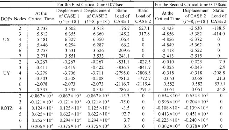
0.03m 2, and 0.0068m 3, respectively. A half sine function load acts in the x-direction at nodes 2 and 3 as a concentrated load, and in the y-direction over each story as a distributed load. Two dominant critical times are selected among the multiple critical times when the displacements have extreme values. They are when the structure moves to the end in the x-direction. The times are 0.074 sec and 0.138 sec. Two approximated ESLs are generated for the first critical time of 0.074 sec. CASE 1 is for the loads which act in all the DOFs, and CASE 2 is for the loads which act in DOFs where the dynamic loads act. For the second critical time, only CASE 2 is calculated. The constraints are selected as total DOFs of 18. The distributed loads in the y-direction are converted to the concentrated loads at each nodes. The displacements at each critical times, the calculated ESLs, and the displacements under the ESLs are shown in Table 2. For the first critical time, the sum of the static loads of CASE 1 in the x-direction is similar to that of CASE 2. The y-directional components of CASE 1 and 2 have similar value at each nodes. The second critical time is calculated as the time when the minimum x-directional displacement happens. The extreme y-direction displacement does not happen at the second critical time. So, the static loads of CASE 2 about the second critical time have opposite value in the x- direction and small value in the y-direction compared to CASE 1 and 2 about the first critical time. The displacements under each ESL set cover the displacements at critical times.Discussion on the Application of the Method in Optimization
The ESL can reduce considerable calculations and cost in stress analysis. However, it can be even more useful in structural optimization than stress analysis. Structural optimization under dynamic load seems to be quite difficult. The dynamic response optimization of rigid body systems have been studied. However, it is a very small system relative to the structural system, although the result was not quite successful. On the other hand, structural optimization under the static load is widely accepted. Using the developed theory here, it is expected that dynamic response optimization can be accomplished for structures. As explained earlier, a dynamic load can be transformed to multiple sets of static loads. The multiple loads can be handled by a multiple loading condition in optimization. It is noted that the ESLs depend on design variables which can be sectional properties and shapes. Thus, they can be changed in an optimization iteration and can be changed even in an iteration of an algorithm which uses a line search. Therefore, sensitivity analyses are needed in each iteration and much evaluation of the static loads are also needed. It is well known that those calculations are very expensive. This difficulty can be overcome by assuming the static loads to be constant in an iteration. The authors are doing numerical experimentation for dynamic structural optimization with the above methods.
C O N C L U S I O N
A C K N O W L E D G M E N T
This project has been carried out under the nuclear R&D program by MOST (Minister Of Science and Technology).
R E F E R E N C E S
1. Bathe, K.J., Finite Element Procedures in Engineering Analysis, Prentice Hall, Englewood Cliffs, New Jersey, U.S.A., 1982.
2. Haug, E.J. and Arora, J.S., Applied Optimal Design, Wiley & Sons, New York, U.S.A., 1979.
3. Feng, T.T., Arora, J.S., and Haug, E.J., "Optimal Structural Design under Dynamic Loads", Int. J. for Num. Mech. in Eng., Vol. 11, 1977, pp. 39-62.
4. Haug, E.J., Arora, J.S., and Feng, T.T., "Sensitivity Analysis and Optimization of Structures for Dynamic Response", J. of Mech. Design, Vol 100, 1978, pp. 311-318.
5. Hsieh, C.C. and Arora, J.S., "Design Sensitivity and Optimization of Dynamic Response", Comput. Meths. Appl. Mech. Engrg., Vol. 43, No. 2, 1984, pp. 195-219.
6. James, M.L. et. al., Vibration of Mechanical and Structural Systems, 2nd edn, Harper Collins, New York, U.S.A., 1994. 7. Clough, R.W., Dynamics of Structures, McGraw Hill, New York, U.S.A., 1993.
8. Haftka, R.T. and Gtirdal, Z., Elements of Structural Optimization, Kluwer Academic Publishers, The Netherlands, 1991. 9. Shin, M.J., Choi, W.S., and Park, G.J., "Transformation of a Dynamic Load into an Equivalent Static load and Shape Optimization of the Road Arm", PACAM V Conference, Puerto Rico, 1997.
10. Choi, W.S., Kang, S.C., Shin, M.J., and Park, G.J., "Transformation of a Dynamic Load into an Equivalent Static Load and Shape Optimization of the Road Arm", Transactions of the Korean Society of Mechanical Engineers(A), 20(12), 3767- 3781, 1996 (in Korean).
11. Choi, W.S., Kang, B.S., and Park, G.J., "Transformation of Dynamic Loads into Equivalent Static Loads Based on Modal Analysis", Transactions of the Korean Society of Mechanical Engineers(A), 22(7), 1193-1204, 1998 (in Korean).
12. Grandhi, R.V., Haftka, R.T., and Watson, L.T., "Design-Oriented Identification of Critical Times in Transient Response", AIAA Journal, 24(4), 649-656, 1986.
13. Arora, J.S. and Tseng, C.H., User's Manual for IDESIGN : Version 3.5 Optimal Design Laboratory, College of Engineering, The University of Iowa, Iowa City, U.S.A., 1987.
14. ANSYS User's Manual, Revision 5.3, Swanson Analysis Systems, Inc.
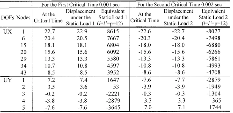
Table 1 The results for 124 bar truss example (Newton, cm)
For the First Critical Time 0.001 sec For the Second Critical Time 0.002 sec
DOFs Nodes
UX 1
6 15 20 29 34 43
UY 1
2 3 4 5
At the Displacement Equivalent
under the Static Load 1 Critical Time Static Load 1 (/=/'=p=12)
22.7 22.9 8615
20.4 20.5 7667
18.1 18.1 6804
15.6 15.6 6092
13.3 13.3 5580
10.7 10.8 4597
8.5 8.5 3952
7.2 7.4 1647
3.5 3.6 53
-0.2 -0.2 -2221
-3.8 -3.8 -2879
-7.6 -7.6 -3645
At the Displacement Equivalent
under the Static Load 2 Critical Time
Static Load 2 (l=l'=p=12)
-22.6 -22.7 -8077
-20.3 -20.4 -7498
-18.0 -18.0 -6880
-15.6 -15.6 -6266
-13.3 -13.3 -5861
-10.8 -10.8 -4993
-8.6 -8.6 -4708
-7.6 -7.7 -2879
-3.9 -3.9 -1949
-0.3 -0.3 - 1304
3.3 3.3 365
124b ar t[uss
'6 / 8
L
~6 u2 ",Tf 63
,! / ,o \
- \ /
lO5 1~' " ~ l O Z I 3.66m
9.14m
~/___
F(t) kN
4.45
0.001 Time (sec)
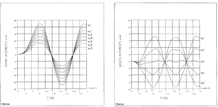
Fig. 1 An 124 member plane truss structure and the profile of applied dynamic load
1245artruss
Fig. 2
ux 15 f - - " ux 20
f " - - " ux 34
: > 101~I-3'I
3 .:'; ':;' i . , ~ 2".3 2 7
TZ F1E
Displacements vs. time in x-direction
124bartruss
- ' - - - ~ ~_I
uy_2
~-~ ~_~
~
~-~
i . ' / /
,.J
~_~
/ /
~ /
~-~
o 3
.~ .q 1.5 2.J ;.7 TZHE
L o a d 1
L o a d 2 ( ~ ~ ~J ~ ~ ~/ ~/ ~ ~/ ~] ~ / @
/
3
]@
4
F ( t ) 4 . 6 m 2
L o a d 1 2 0 0 . 3 k N ... ..L...oad 2
5
6
876 kN/rr@
1
4 . 6 m 0 . 1 0 2 T i m e ( s e c )
V
®
,.- x
9 , / /
/ 6 . 1 m -.~
F i g . 4 1 - b a y 2 - s t o r y s t r u c t u r e a n d h i s t o r y l o a d
T a b l e 2
DOFs Nodes
2 3 UX 4 5 6 7 2 3 UY 4 5 6 7 2 3 ROTZ 4 5 6 7
T h e r e s u l t s f o r 1 b a y 2 s t o r y e x a m p l e ( k N , c m ) For the First Critical time 0.074sec
At the Displacement Displacement Static Static of CASE 1 of CASE 2 Load of Load of Critical Time
(/'=p=l 8 ) (/'=8, p=l 8 ) CASE 1 CASE 2 2.733 3.502 3.518 176.7 627.1 5.512 6.355 6.360 145.2 317.8 5.481 6.327 6.350 106.4 0 5.446 6.294 6.287 66.2 0 2.753 3.531 3.526 209.6 0 2.771 3.551 3.533 241.1 0 -0.267 -0.267 -0.267 -831.1 -822.5 -0.411 -0.419 -0.422 -836.7 -841.7 -3.279 -3.706 -3.711 -2798.0 -2806.5 -0.503 -0.508 -0.508 -781.2 -772 7 -2.078 -2.073 -2.073 -2116.7 -2115.4 -0.335 -0.335 -0.335 -786.5 -791.5
For the Second Critical time 0.138sec
-2.423 -2.530 -188.5 -4.856 -5.382 -414.0 -4.856 -5.372 0 -4.849 -5.362 0 -2.418 -2.522 0 -2.413 -2.515 0 -0.010 -0.023 7.5 -0.025 -0.043 2.9 -0.318 -0.318 -208.8 0.053 0.058 21.3 0.582 0.582 539.1 0.051 0.051 24.8
0 . 6 5 4 x 10 -2 0.654 x 10 .2 0 0.996x 10 .3 0.204 x 10 .2 0 -0.108x10 .2 -0.139x10 .2 0 0.413 x 10 .2 0.451 x 10 .2 0 -0.225 x 10 .2 -0.240 x 10 .2 0 0.302 x 10 .2 0.378 x 10 .2 0 D i s p l a c e m e n t a n d l o a d u n i t s o f r o t a t i o n D O F a r e r a d i a n a n d k N . c m , r e s p e c t i v e l y .
-0.867x10 .2 -0.867x10 .2 -0.867x10 -2 -15.3 0 -0.121x10 -~ -0.121x10 ~ -0.121×10 ~ -75.0 0 0.124x 10 .2 0.125x 10 .2 0.125 x 10 .2 -3.5 0 0.625 x 10 .2 0.622 x 10 .2 0.622 x 10 .2 92.7 0 0.252 x 10 .2 0.294 x 10 .2 0.294x 10 .2 3.7 0 -0.206x10 .2 -0.375x10 .2 -0.375x10 .2 3.5 0
At the Displacement Static of CASE 2 Load of Critical Time