bbbbbbbbbbbbbbbbbbbbbbbbbbbbbbbbbbbbbbbbbbbbb
bbbbb
555-230-220 September 1995
DEFINITY
Communications
System
Generic 3V4
CallVisor
ASAI Technical Reference
bbbbbbbbbbbbbbbbbbbbbbbbbbbbbbbbbbbbbbbbbbbbb
bbbbb
Copyright1993 AT&T All Rights Reserved Printed in USA
Notice
While reasonable effort was made to ensure that the information in this document was complete and accurate at the time of printing, AT&T cannot assume responsibility for any errors. Changes and/or corrections to the information contained in this document may be incorporated into future issues.
Your Responsibility for Your System’s Security
Toll fraud is the unauthorized use of your telecommunications system by an unauthorized third party, for example, persons other than your company’s employees, agents, subcontractors, or persons working on your company’s behalf. Note that there may be a risk of toll fraud associated with your telecommunications system, and if toll fraud occurs, it can result in substantial additional charges for your telecommunications services.
You and your system manager are responsible for the security of your system, such as programming and configuring your equipment to prevent unauthorized use. The System Manager is also responsible for reading all installation, instruction, and system administration documents provided with this product in order to fully understand the features that can introduce risk of toll fraud and the steps that can be taken to reduce that risk. AT&T does not warrant that this product is immune from or will prevent unauthorized use of common-carrier telecommunication services or facilities accessed through or connected to it. AT&T will not be responsible for any charges that result from such unauthorized use.
AT&T Corporate Security
Whether or not immediate support is required, all toll fraud incidents involving AT&T products or services should be reported to AT&T Corporate Secuirty at 1 800 821-8235. In addition to recording the incident, AT&T Corporate Security is available for consultation on security issues, investigation support, referral to law enforcement agencies, and educational programs.
AT&T Fraud Intervention
If you suspect you are are being victimized by toll fraud and you need technical support or
assistance, call the GBCS Technical Service Center Toll Fraud Intervention Hotline at 1 800 643-2353.
Federal Communications Commission (FCC) Statement
This equipment generates, uses, and can radiate radio-frequency energy and, if not installed and used in accordance with the instruction manual, may cause interference to radio communications. It has been tested and found to comply with the limits for a Class A computing device pursuant to Subpart J of Part 15 of FCC Rules, which are designed to provide reasonable protection against such interference when operated in a commercial environment.
Operation of this equipment in a residential area is likely to cause interference, in which case the user at his or her own expense will be required to take whatever measures may be required to correct the interference.
Trademarks
DEFINITY, CallVisor, MultiQuest, and Vari-A-Bill are registered trademarks of AT&T.
UNIX is a registered trademark of Novell in the United States and other countries, licensed exclusively through X/Open Company Limited. Netware Telephony Services is a registered trademark of Novell.
PassageWay Telephony Services is a trademark of AT&T.
Ordering Information
Call: AT&T GBCS Publications Fulfillment Center Voice 1 800 457-1235
Fax 1 800 457-1764
International Voice.: 1 317 361-5353 International Fax: 1 317 361-5355
Write: AT&T GBCS Publications Fulfillment Center P.O. Box 4100
Crawfordsville, IN 47933
Order: Document No. AT&T 555-230-220 Issue 4, September 1995
Published by
GBCSystems Product Documentation Development Group AT&T Bell Laboratories
bbbbbbbbbbbbbbbbbbbbbbbbbbbbbbbbbbbbbbbbbbbbb
bbbbb
bbbbb
Contents
bbbbbbbbbbbbbbbbbbbbbbbbbbbbbbbbbbbb
bb
About This Document
xviiIntended Audience xvii Terminology xviii Conventions Used in This Document xviii Related Documents xix
bbbbbbbbbbbbbbbbbbbbbbbbbbbbbbbbbbbb
bb
1
ASAI and Capability Groups
1-1Introduction 1-1 Capabilities 1-3
bbbbbbbbbbbbbbbbbbbbbbbbbbbbbbbbbbbb
bb
2
ASAI and Supported Applications
2-1Introduction 2-1 Applications 2-2 Sample Applications 2-3 Inbound Call Management 2-5 Office Automation 2-12 Additional Configurations 2-16
bbbbbbbbbbbbbbbbbbbbbbbbbbbbbbbbbbbb
bb
3
Event Reporting and U-Abort Capabilities
3-1Introduction 3-1 Event Reports 3-2 U-ABORT 3-46
bbbbbbbbbbbbbbbbbbbbbbbbbbbbbbbbbbbb
bb
bbbbbbbbbbbbbbbbbbbbbbbbbbbbbbbbbbbbbbbbbbbbb
bbbbb
bbbbb
Contents
Third Party Merge 4-38 Third Party Selective Drop 4-42 Third Party Relinquish Control 4-44 Third Party Clear Call 4-45 Third Party Send DTMF Signals (G3V4) 4-47 Third Party Call Ended 4-50
bbbbbbbbbbbbbbbbbbbbbbbbbbbbbbbbbbbb
bb
5
ASAI and Domain Control
5-1Domain (Station) Control Description 5-3 Domain Call Control Capabilities 5-4 Third Party Domain (Station) Control Request 5-5 Third Party Domain Control Request for ACD Split/
EAS Skill Domain 5-7 Third Party Answer 5-9 Third Party Selective Hold 5-12 Third Party Reconnect 5-14 Redirect Call 5-16 Third Party Merge 5-19 Third Party Selective Drop 5-22 Third Party Auto Dial 5-24 Third Party Relinquish Control 5-26 Third Party Send DTMF Signals 5-28 Third Party Domain Control Ended 5-30
bbbbbbbbbbbbbbbbbbbbbbbbbbbbbbbbbbbb
bb
6
Event Notification Capabilities
6-1Event Notification Request 6-2 Event Notification Cancel 6-4 Stop Call Notification 6-5 Event Notification Ended 6-7
bbbbbbbbbbbbbbbbbbbbbbbbbbbbbbbbbbbb
bb
7
ASAI and Call Routing
7-1Route 7-2
bbbbbbbbbbbbbbbbbbbbbbbbbbbbbbbbbbbbbbbbbbbbb
bbbbb
bbbbb
Contents
bbbbbbbbbbbbbbbbbbbbbbbbbbbbbbbbbbbb
bb
8
ASAI and Request Feature Capabilities
8-1Request Feature Capability Group 8-2
bbbbbbbbbbbbbbbbbbbbbbbbbbbbbbbbbbbb
bb
9
ASAI and Value Query Capabilities
9-1Value Query 9-2 Value Query Response 9-14
bbbbbbbbbbbbbbbbbbbbbbbbbbbbbbbbbbbb
bb
10
ASAI and Set Value Capabilities
10-1Set Value 10-2
bbbbbbbbbbbbbbbbbbbbbbbbbbbbbbbbbbbb
bb
11
ASAI Maintenance Capabilities
11-1Heartbeat 11-2 Suspend Alarms 11-3 Resume Alarms 11-5 Restart 11-6 Link Versions 11-6
bbbbbbbbbbbbbbbbbbbbbbbbbbbbbbbbbbbb
bb
12
ASAI and Feature Interactions
12-1bbbbbbbbbbbbbbbbbbbbbbbbbbbbbbbbbbbbbbbbbbbbb
bbbbb
bbbbb
Contents
BCMS Login IDs 12-12 Bridged Call Appearance 12-12 Busy Verification of Terminals 12-13 Call Coverage 12-13 Call Forwarding All Calls 12-15 Call Park 12-16 Call Pickup 12-16 Call Vectoring 12-17 Call Waiting 12-20 Class of Restriction (COR) 12-20 Class of Service (COS) 12-21 Conference 12-21
DCS 12-21
Direct Agent Calling 12-22 Do Not Disturb 12-27 Drop Button Operation 12-27 Duplication 12-28 Expansion Port Network (EPN) 12-28 Expert Agent Selection (EAS) 12-28 Facility Restriction Levels (FRLs) 12-34 Forced Entry of Account Codes 12-34
Hold 12-34
bbbbbbbbbbbbbbbbbbbbbbbbbbbbbbbbbbbbbbbbbbbbb
bbbbb
bbbbb
Contents
Terminating Extension Group (TEG) 12-39 Timed Reminder 12-40 Transfer 12-41 Trunk-to-Trunk Transfer 12-41 Voice (Synthesized) Message Retrieval 12-41
bbbbbbbbbbbbbbbbbbbbbbbbbbbbbbbbbbbb
bb
13
ASAI-Ethernet
13-1Overview 13-1 Physical Connectivity 13-1 Administration 13-5 System Operation 13-6
bbbbbbbbbbbbbbbbbbbbbbbbbbbbbbbbbbbb
bb
14
Installation and Test for CallVisor ASAI
14-1Hardware Installation 14-1 Software Installation 14-2 CallVisor ASAI Link Administration 14-3 CallVisor ASAI Link Testing 14-6 AT&T Vendor Partners 14-6
bbbbbbbbbbbbbbbbbbbbbbbbbbbbbbbbbbbb
bb
A
Call Scenarios and Applications
A-1bbbbbbbbbbbbbbbbbbbbbbbbbbbbbbbbbbbbbbbbbbbbb
bbbbb
bbbbb
Contents
bbbbbbbbbbbbbbbbbbbbbbbbbbbbbbbbbbbb
bb
B
ASAI and Generic 3 Switch Requirements
B-1Capacity Requirements and Constraints B-1
bbbbbbbbbbbbbbbbbbbbbbbbbbbbbbbbbbbb
bb
GL
Glossary
GL-1bbbbbbbbbbbbbbbbbbbbbbbbbbbbbbbbbbbb
bb
bbbbbbbbbbbbbbbbbbbbbbbbbbbbbbbbbbbbbbbbbbbbb
bbbbb
bbbbb
Figures
bbbbbbbbbbbbbbbbbbbbbbbbbbbbbbbbbbbb
bb
2
ASAI and Supported Applications
2-1. Single Link — Single Processor Configuration 2-1 2-2. Multiple Link — Single Processor Configuration 2-16 2-3. Single Link — Multiple Processors Configuration 2-17 2-4. Single Link — Gateway/Server Configuration 2-18 2-5. ASAI Integration with a VRU Configuration 2-19
bbbbbbbbbbbbbbbbbbbbbbbbbbbbbbbbbbbb
bb
13
ASAI-Ethernet
13-1. DEFINITY LAN Gateway System Assembly in a
DEFINITY Carrier 13-2 13-2. Cable Connectivity to the System Assembly 13-3 13-3. Overall System Connectivity 13-5 13-4. Relationship of Virtual BRI Ports, Brouter, and
DEFINITY LAN Gateway Clients 13-7
bbbbbbbbbbbbbbbbbbbbbbbbbbbbbbbbbbbb
bb
A
Call Scenarios and Applications
A-1. Multiple Switch Configuration A-24 A-2. Call Flow for Blind Transfer to Another Switch A-26 A-3. Call Flow for Consultation Transfer to Another
Switch A-28 A-4. Call Flow for Incoming Call to Lookahead Interflow
Vector A-31 A-5. Call Flow for a Transfer to a Lookahead Interflow
Vector A-34 A-6. Call Flow for Incoming Call to Skill VDN A-38 A-7. Call Flow for Incoming Call to Logical Agent
bbbbbbbbbbbbbbbbbbbbbbbbbbbbbbbbbbbbbbbbbbbbb
bbbbb
bbbbb
Figures
A-14. Call Flow for an Agent who has a VDN in the Coverage
Path A-55
A-15. Call Flow for Call to a VDN with Announcement and Routed to Another VDN A-57 A-16. Outgoing Call over Non-ISDN Trunk A-59 A-17. Call Flow for Outgoing ISDN Call that Traverses
bbbbbbbbbbbbbbbbbbbbbbbbbbbbbbbbbbbbbbbbbbbbb
bbbbb
bbbbb
Tables
bbbbbbbbbbbbbbbbbbbbbbbbbbbbbbbbbbbb
bb
3
Event Reporting and U-Abort Capabilities
3-1. Use of Event Reports in Associations 3-41 3-2. Call Merge Summary 3-45
bbbbbbbbbbbbbbbbbbbbbbbbbbbbbbbbbbbb
bb
4
ASAI and Call Control
4-1. Call Control Acceptance in Various Call/
Station States 4-3 4-2. Detected SITs 4-10 4-3. Third Party Make Call Options 4-26 4-4. Allowable Originators and Destinations for
Specific Call Options 4-26
bbbbbbbbbbbbbbbbbbbbbbbbbbbbbbbbbbbb
bb
5
ASAI and Domain Control
5-1. Call Control Acceptance in Various Party States 5-4
bbbbbbbbbbbbbbbbbbbbbbbbbbbbbbbbbbbb
bb
12
ASAI and Feature Interactions
12-1. Interactions Between Feedback and Call Vectoring 12-17 12-2. Coverage Interactions for ACD Calls without
Priority Calling 12-27 12-3. Coverage Interactions for ACD Calls with Priority
Calling 12-27
bbbbbbbbbbbbbbbbbbbbbbbbbbbbbbbbbbbb
bb
13
ASAI-Ethernet
13-1. Brouter Table Format 13-8
bbbbbbbbbbbbbbbbbbbbbbbbbbbbbbbbbbbb
bbbbbbbbbbbbbbbbbbbbbbbbbbbbbbbbbbbbbbbbbbbbb
bbbbb
bbbbb
Tables
bbbbbbbbbbbbbbbbbbbbbbbbbbbbbbbbbbbb
bb
A
Call Scenarios and Applications
A-1. Incoming Call Routed to External Destination
Example A-66
bbbbbbbbbbbbbbbbbbbbbbbbbbbbbbbbbbbb
bb
B
ASAI and Generic 3 Switch Requirements
bbbbbbbbbbbbbbbbbbbbbbbbbbbbbbbbbbbbbbbbbbbbb
bbbbb
bbbbb
About This Document
bbbbbbbbbbbbbbbbbbbbbbbbbbbbbbbbbbbb
This reference manual provides detailed information regarding the CallVisor Adjunct/Switch Application Interface1 for the Generic 3 switch.
ASAI is a communications interface that allows application processors (called adjuncts in this document) to access switch features and control switch calls. The ASAI is implemented using either an Integrated Services Digital Network (ISDN) Basic Rate Interface (ASAI-BRI) or an Ethernet interface
(ASAI-Ethernet).
Intended Audience
bbbbbbbb
This document is written for the application designer responsible forbuilding/programming custom applications and features. This document is also helpful to any individual who needs a functional description of ASAI.
ASAI provides users with the capability to drive a variety of switch features. It is essential, therefore, that readers of this document possess extensive knowledge regarding not only these switch features themselves, but also their interactions.
About This Document
bbbbbbbbbbbbbbbbbbbbbbbbbbbbbbbbbbbbbbbbbbbbb
bbbbb
Terminology
bbbbbbbb
Definitions of terms relating to ASAI can be found in the glossary at the end ofthis document.
Conventions Used in This Document
bbbbbbbb
The majority of conventions in this document are self-explanatory and need notbe discussed here. There are, however, some conventions whose meaning may not be obvious to the reader. An explanation of these conventions follows. Chapters 3 through 11 detail the function of each feature or capability in this version of ASAI. A capability is a request for or an indication of an operation. For example, dropping a party from a call is a capability of ASAI. Related capabilities are grouped into functional sets called capability groups.2 Each capability within the group is divided into the following subsections:
Capability Name
Provides a short overview of the capability and its functions.
Information Flow
This heading provides information regarding the flow of data from the adjunct to the switch or vice versa. For example, the switch may generate reports to the adjunct (application processor), but the adjunct does not need to respond to these reports. This situation is different when dealing with many of the call control capabilities that require a give and take of data between the switch and the adjunct.
<Capability Name> Parameter(s)
This heading documents the type of information (such as the caller_id) that passes between the switch and the adjunct (usually in the form of a request to the switch). The actual name is based on the capability being discussed; for example, Call Control Parameters.
aaaaaaaaaaaaaaaaaaa
About This Document
bbbbbbbbbbbbbbbbbbbbbbbbbbbbbbbbbbbbbbbbbbbbb
bbbbb
ACK (positive acknowledgement) Parameter(s)
There are many instances when the switch simply acknowledges the request made by the adjunct and subsequently performs the operation. There are other times when the switch replies with specific information (such as the identity of the party making the call) to the adjunct within the acknowledgement.
Denial (NAK) Cause(s)
This heading designates a negative acknowledgement (NAK) from the switch. This means that the information provided by the adjunct to the switch was incorrect; for example, one of the parameters, such as the call_id, was incorrect. At this point the switch rejects the request and terminates the communication channel between the switch and the adjunct. The switch also provides a reason why the operation was not performed. These reasons or causes fall under the Denial (NAK) Cause(s).
Each ASAI capability contains a Denial (NAK) section with a list of cause | calues most commonly occurring. An attempt was made to have these | lists complete. However, because of the many unpredictable | switch/feature interactions, it is possible that those lists are not complete. | Therefore, application and ASAI library writers should be able to handle | any other (valid) cause values not listed under the particular capability.
Protocol (NAK) Error Cause(s)
This heading designates a protocol processing error.
Considerations
This heading provides the user with any special information that should be taken into account for this particular capability.
Related Documents
bbbbbbbb
AT&T Adjunct/Switch Application Interface Specification (ASAI),555-025-203
About This Document
bbbbbbbbbbbbbbbbbbbbbbbbbbbbbbbbbbbbbbbbbbbbb
bbbbb
AT&T DEFINITY Communications System Generic 3 CallVisor ASAI Protocol Reference, 555-230-221
The Protocol Reference provides detailed protocol information of CallVisor Adjunct Switch Application Interface (ASAI) for the Generic 3 switch.
NOTE:
Distribution of this document is restricted to AT&T.
AT&T DEFINITY Communications System Generic 3 Installation, Administration, and Maintenance of CallVisor ASAI Over DEFINITY LAN Gateway, 555-230-223 This document describes the installation, administration, and maintenance of the ASAI-Ethernet application, which provides ASAI functionality using 10Base-T Ethernet rather than BRI as a transport media.
AT&T DEFINITY Communications System Generic 3 Feature Description, 555-230-204
The Feature Description serves as an overall reference for the planning, operation, and administration stages of Generic 3 switch.
AT&T DEFINITY Communications System Generic 3 System Description, 555-230-206
This manual provides a technical description of hardware, environmental, and space requirements and parameters.
AT&T DEFINITY Communications System Generic 3 V4 Implementation, 555-230-655
This manual documents the implementation of the Generic 3i switch.
AT&T DEFINITY Communications System Generic 3 Call Vectoring/EAS Guide, 555-230-520
This manual documents call vectoring for the Generic 3 switch. GBCS Products Security Handbook, 555-025-600
This manual provides information on securing various AT&T products against toll fraud.
NOTE:
About This Document
bbbbbbbbbbbbbbbbbbbbbbbbbbbbbbbbbbbbbbbbbbbbb
bbbbb
bbbbb
ASAI and Capability Groups
1
bbbbbbbbbbbbbbbbbbbbbbbbbbbbbbbbbbbb
Introduction
bbbbbbbb
The purpose of this chapter is to present an overview of ASAI and the services itprovides.
ASAI services are divided into functional sets called capability groups.1 Capability groups enable the adjunct2 to communicate with and control the switch.3
aaaaaaaaaaaaaaaaaaa
1. Capability groups are analogous to Application Service Elements (ASEs) described in the AT&T Adjunct/Switch Application Interface (ASAI) Specification, 555-025-203.
2. For the purpose of this document, the term adjunct is defined as the application processor.
ASAI and Capability Groups
bbbbbbbbbbbbbbbbbbbbbbbbbbbbbbbbbbbbbbbbbbbbb
bbbbb
Each capability group is defined by the set of functions within it. ASAI defines eight capability groups in all:
Call Control4 The capabilities in this group enable the adjunct to place, monitor, and control any party on a single call as it moves through the switch.
Domain (Station/ACD Split) Control4
The station capabilities in this group enable the adjunct to place, monitor, and control all calls at a specific station domain.
This capability group also enables the adjunct to receive reports as to the status of agents on an ACD split. Currently the switch provides the Logout Event, and, starting with G3V4, the Login Event.
Notification This capability group lets the adjunct request and cancel event reporting on certain calls.
Routing This capability group allows the switch to ask the adjunct for a call’s destination. The adjunct supplies the destination based on call-related information (for example, called number).
Request Feature
The single capability in this group lets the adjunct request switch features, such as the agent login, logout, work mode changes, Call Forwarding, and Send All Calls (SAC).
Value Query This capability group enables the adjunct to request
information regarding switch resources. Using this capability group would, for example, allow a user to query the switch for the number of agents currently logged in to an ACD split.
Set Value This capability group enables the adjunct to set switch-controlled services, such as the Message Waiting Indicator (MWI), for any specified telephone set.
ASAI and Capability Groups
bbbbbbbbbbbbbbbbbbbbbbbbbbbbbbbbbbbbbbbbbbbbb
bbbbb
Capabilities
bbbbbbbb
While capabilities are grouped by the services they may provide, all groupsdivide their particular capabilities into three categories or types. These categories are: initiating, controlling, and terminating capabilities.
Initiating These capabilities are used to open a channel of
communication between the adjunct and the switch for messaging purposes. An example of an initiating capability is Third Party Make Call that allows the adjunct to direct the switch to place a call.
Controlling These capabilities are used to exchange information once the channel of communication has been
established. For example, Third Party Selective Hold can be used to place a call on hold, or Third Party Merge can be used to transfer a call.
Terminating These capabilities end or close the channel of communication between the adjunct and the switch. For example, Third Party Call Ended indicates that the call has ended.
Capabilities and Associations
bbbbbbbbbbbbbbb
Central to this introduction of capability groups and ASAI in general is the concept of an association. An association is defined as a channel of
communication between the adjunct and the switch for messaging purposes. It may be helpful to think of an association as a communications session; each session could involve information pertaining to many calls.
The previous section regarding types of capabilities showed that all capabilities act across a channel of communication which is an association. Initiating capabilities begin an association, controlling capabilities manipulate message exchange during the association, and terminating capabilities end the
association.
Associations and Capability Groups
bbbbbbbbbbbbbbb
ASAI defines eight different types of associations, each of which corresponds to a particular capability group:
Call Control Associations
Domain (Station/ACD Split) Control Associations Notification Associations
ASAI and Capability Groups
bbbbbbbbbbbbbbbbbbbbbbbbbbbbbbbbbbbbbbbbbbbbb
bbbbb
bbbbbbbbbbbbbbbbbbbbbbbbbbbbbbbbbbbbbbbbbbbbb
bbbbb
bbbbb
ASAI and Supported
Applications
2
bbbbbbbbbbbbbbbbbbbbbbbbbbbbbbbbbbbb
Introduction
bbbbbbbb
This chapter provides a look at the various configurations and applications thatcan be supported by the ASAI capabilities.
The first part of this chapter presents a simple configuration and several application samples. The latter part provides additional configurations that support the ASAI capabilities, and a table that defines the capacity limitations of ASAI.
Figure 2-1 illustrates the simplest configuration, an adjunct (application processor) connected to a switch via a single ASAI-BRI/Ethernet link.
bbbbbbbbbbbbbbbbbbbbb
BRI/Ethernet ASAI Adjunct
Application G3
bbbbbbbbbbbbbbbbbbbbbbbbbbbbbbbb
ASAI and Supported Applications
bbbbbbbbbbbbbbbbbbbbbbbbbbbbbbbbbbbbbbbbbbbbb
bbbbb
The adjunct can be a personal computer, a minicomputer, or a mainframe. Applications on the same adjunct monitor and control voice calls or perform other operations on behalf of a telephone user.
Applications on the adjunct can share the ASAI link when communicating with the switch. The switch does not distinguish between multiple applications that may be sharing a switch link.
A user typically has a telephone and a data terminal at his or her desk. The user can control the voice calls at his or her telephone by using the telephone or entering commands at the data terminal. When using the data terminal, the application controls the voice call via the ASAI link. How the data terminal is connected to the adjunct is irrelevant to the ASAI-supported applications described in this document.
Applications
bbbbbbbb
ASAI supports a variety of application types:Those that control a single station (telephone set) on behalf of a specific user
Those that control all parties on a call Those that route incoming calls
Those that make outbound calls from an ACD split for a telemarketing center
Those that monitor calls entering vectors and/or ACD splits
The Generic 3 switch allows an application to control a specific extension on a call and, at the same time, allows another application to control another extension on the call. In this case, both applications can independently control endpoints on the call in the same way that users can by using their telephone set.
ASAI and Supported Applications
bbbbbbbbbbbbbbbbbbbbbbbbbbbbbbbbbbbbbbbbbbbbb
bbbbb
Sample Applications
bbbbbbbb
The sample applications in the following section provide a practical, ‘‘real world’’illustration of ASAI capabilities.
NOTE:
The applications described in this section are not restricted to any particular configuration described in this section, nor are they mutually exclusive. Any configuration and group of applications can be used simultaneously. The switch does not restrict any mix of applications, except as dictated by capacity and performance constraints. For
information on ASAI capacity limits, see Appendix B, ‘‘ASAI and Generic 3 Switch Requirements.’’
In addition, the ASAI interface provided by the switch is not the only system component that might be needed to provide these applications. For example, additional hardware (computer data terminals, voice response units, call classifier boards) and/or software (application interface, call vectoring) might be needed. The ASAI interface only provides the communication link to access the switch services that make these applications possible.
Outbound Call Management
bbbbbbbbbbbbbbb
A good example of Outbound Call Management (OCM) is an Outbound
Telephone Support Center Application. An Outbound Telephone Support Center Application automatically generates outbound calls that are to be handled by a specified user community (agent pool).
Outbound applications fall into two categories:
Preview Dialing — The agent or user previews a screen of data pertaining to
the call and enters information into the system when ready to make the call. Preview dialing allows an agent or user to control when the outbound call is started, enabling the user to prepare for a conversation with the called party.
Predictive Dialing — The adjunct application makes more outbound calls than
there are agents. Statistically, a certain number of calls will go unanswered, busy, intercept, or answered by machine detection (if so optioned), etc. The system connects agents only with answered calls. Predictive dialing makes more efficient use of an agent pool by eliminating dialing time, listening to ringing, etc.
ASAI and Supported Applications
bbbbbbbbbbbbbbbbbbbbbbbbbbbbbbbbbbbbbbbbbbbbb
bbbbb
Preview Dialing
1. The agent uses a data terminal to log into the outbound telephone support application. The application establishes a Domain (Station) Control association for the agent. There must be one such association for each agent.
2. The agent enters information indicating readiness to preview data. There must be one such association for each agent.
3. The adjunct application displays a screen of data to the agent.
4. When the agent enters information, the application uses the ASAI Third Party Auto-Dial capability to place an outbound call from the agent’s station to the number associated with the displayed data. See ‘‘Domain (Station ACD Split) Control’’ in Chapter 5 for more information regarding the Third Party Auto-Dial capability. Alternately, when the agent enters information, the application uses the ASAI Third Party Make Call Capability to place an outbound call from the agent to the number
associated with the displayed data. See ‘‘Call Control Capability Group’’ in Chapter 4 for more information regarding the Third Party Make Call
Capability.
5. The switch sends the adjunct event reports about the call for agent tracking until the call disconnects.
6. The cycle continues.
Predictive Dialing
Predictive dialing uses special hardware, a call classifier. The call classifier is capable of detecting ringing, voice energy, special tones, and an answering machine.
1. A user (agent) uses either a telephone set or data terminal to log into the outbound telephone support application. If the user uses the data terminal, then the adjunct application uses the ASAI Request Feature Capability to log the agent into the ACD split on the switch.
ASAI and Supported Applications
bbbbbbbbbbbbbbbbbbbbbbbbbbbbbbbbbbbbbbbbbbbbb
bbbbb
4. The switch provides the adjunct application(s) with event reports for call activity within the ACD split. The application, in turn, might display information from the calling list to an agent when the switch ACD software connects an outbound call to an agent.
5. The cycle continues.
6. For G3V3 and later, the Answering Machine Detection feature may be used in conjunction with this type of dialing to receive Connected Event Reports on any type of trunk.
Inbound Call Management
bbbbbbbb
Inbound Call Management (ICM) provides inbound telemarketing centers with theability to increase ACD agent efficiency and tracking by enabling ICM applications to:
Monitor (receive ASAI Event Reports) all calls delivered to Vector Directory Numbers (VDNs) and ACD splits and calls originated by ACD agents or users
Route calls to specific ACD/hunt groups, VDNs, or ACD agents based on incoming call information [for example, Calling Party Number/Billing Number (CPN/BN)1 and Dialed Number Identification Service (DNIS)]2 and ACD call activity (for example, total number of calls queued, or number of available agents)
Prepare and deliver, together with the voice call, the appropriate data screen to the selected agent or user
Duplicate and transfer the caller’s data screen when an ACD agent or user conferences or transfers the voice call to another destination (for example, ACD supervisor, or expert agent)
Provide ACD agent functions (for example, login, logout, or work mode change) from a data terminal
Provide ACD agents and/or supervisors with Internally Measured Data on the performance of agents, splits, trunk groups, or VDNs.
Set the billing rate for calls to a 900-number with AT&T MultiQuest Vari-A-Bill service.
aaaaaaaaaaaaaaaaaaa
1. CPN/BN information can be used by the ICM application to identify the caller so that the caller information can be retrieved from an application database. In addition, CPN/BN allows the application to gather statistics about the callers’ geographical locations and to assess the effectiveness of different marketing campaigns.
ASAI and Supported Applications
bbbbbbbbbbbbbbbbbbbbbbbbbbbbbbbbbbbbbbbbbbbbb
bbbbb
The following sample scenarios illustrate the operation of several ICM applications.
ACD Call Activity Monitoring
bbbbbbbbbbbbbbb
The ACD Call Activity Monitoring Application uses event reporting to track the call activity of VDNs, ACD splits, and individual agents or users. (For G3V3 and later, Multiple Monitors provides the ability for up to three ASAI applications to monitor the same ACD Split or VDN domain.)
The application may use the event reports to generate ACD reports containing information such as the following:
Call distribution by CPN/BN3 for each DNIS
Total number of calls handled by each VDN, ACD split, and/or agent Total number of calls, with CPN/BN, that abandon/drop while in queue Total number of ACD, agent-to-agent, agent-to-supervisor, and personal calls that were originated and received by each agent
Average and maximum time in queue Average and maximum queue length Average and maximum call holding time Average time spent by each agent on a call Total number of calls that interflow/intraflow
In addition, if the application has complete control of the agent work modes, such as in adjunct-controlled splits, the agent activity reports can also be generated. A sample scenario for the ACD Call Activity Monitoring application is as follows:
1. The application uses the Event Notification Request Capabilities and Domain Control Capabilities to monitor all calls delivered to ACD splits and all calls originated and delivered to an agent station.
2. The switch sends event reports (for example, Call Initiated, Alerting, Connected, Call Transferred, or Dropped) to the application for all calls entering the monitored ACD splits and stations.
ASAI and Supported Applications
bbbbbbbbbbbbbbbbbbbbbbbbbbbbbbbbbbbbbbbbbbbbb
bbbbb
Data Screen Delivery and Voice/Data
Transfer
bbbbbbbbbbbbbbb
A Data Screen Delivery and Voice/Data Transfer application may use CPN/BN or calling party number, DNIS or called party number, and answering destination information to construct and deliver a data screen to the answering agent/user’s data terminal. Likewise, when an agent or user conferences or transfers a call, the application uses the conferenced agent or transferred-to agent information to automatically transfer the data screen to the new agent handling the call.
A sample scenario for the Data Screen Delivery and Voice/Data Transfer application is as follows:
1. The application uses the Event Notification Request capability to monitor all incoming calls to an ACD split or VDN.
2. When a call enters the monitored ACD split or VDN, the switch sends a Call Offered to Domain Event Report containing the call’s CPN/BN, DNIS, UUI (whether supplied by the network or by some other CallVisor adjunct), and any lookahead interflow and collected digits information associated with the call.
3. The application does a database search on the caller information
(CPN/BN) and retrieves the caller’s data to fill a data screen based on the service dialed (DNIS).
4. When the call is delivered to an available agent and/or user, the switch sends an Alerting and/or Connected Event Report containing the number of the agent or user handling the call. The application then delivers the assembled data screen to the data terminal associated with the agent or user handling the call.
5. If the agent or user conferences or transfers the call to another destination, the switch sends a Call Conferenced or Call Transferred Event Report indicating the new destination. The application then duplicates or recreates the caller’s data screen at the data terminal associated with the new destination.
6. When an agent or caller disconnects and/or drops, the
ASAI and Supported Applications
bbbbbbbbbbbbbbbbbbbbbbbbbbbbbbbbbbbbbbbbbbbbb
bbbbb
Data Screen Delivery with Call Prompting
bbbbbbbbbbbbbbb
The application can also use the switch-based Call Prompting feature to obtain additional information (for example, account number) from the caller. The entered information can be used to select the appropriate data screen.
A sample scenario for the Data Screen Delivery with Call Prompting application is as follows:
1. The customer administers a vector with a Collect Digits command as part of the Call Prompting feature.
2. The application uses the Event Notification Request capability to monitor all incoming calls to the VDN used to distribute calls to agents or users. 3. When a call enters the monitored VDN, the switch sends a Call Offered to
Domain Event Report containing the digits collected for the call in the Collect Digits vector command.
4. The application does a database search on the digits collected and retrieves the caller’s data to fill a data screen based on the service dialed. 5. When the call is delivered to an available agent and/or user, the switch
sends an Alerting and/or Connected Event Report containing the number of the agent or user handling the call. The application then delivers the assembled data screen to the data terminal associated with the agent or user handling the call.
Speech Processing Integration
bbbbbbbbbbbbbbb
Speech Processing Integration can be achieved if the application uses a Voice Response Unit (VRU) to interact with the caller. The VRU is an adjunct and calls are delivered to VRU ports for announcements and collection of additional information from the caller. The application communicates with the VRU software and uses the information provided by the caller to prepare the
appropriate data screen and/or route the call to the appropriate destination (for example, ACD agent).
A sample scenario for the Speech Processing Integration application is as follows:
1. The customer administers the VRU ports as ACD agents in an ACD split. To the switch the VRU ports look like ACD agents.
ASAI and Supported Applications
bbbbbbbbbbbbbbbbbbbbbbbbbbbbbbbbbbbbbbbbbbbbb
bbbbb
4. When a call enters the monitored ACD split or VDN, the switch starts sending Event Reports to the application about the call including the Call Offered to Domain Event Report containing the call’s CPN/BN, DNIS, and any lookahead interflow and collected digits information associated with the call.
5. When a call is connected to the VRU, the application uses the VRU’s voice processing capabilities to interact with the caller. The caller, after interacting with the VRU (for example, listening to account balances or transferring funds), may choose to talk to an agent.
6. The application uses Call Control Capabilities (for example, Third Party Selective Hold, Third Party Make Call, and Third Party Merge) to transfer the call to the agent or group of agents (ACD split) designated to handle this type of caller.
7. When the call is delivered to an available agent, the switch sends an Alerting and/or Connected Event Report containing the number of the agent handling the call. The application then delivers the assembled data screen to the data terminal associated with the agent handling the call. Typically, the VRU is handing this information off to a host that will be delivering the data screen to the appropriate agent.
Adjunct Routing
bbbbbbbbbbbbbbb
The Adjunct Routing application allows the switch to request call routing instructions (that is, destination) from an adjunct application.
A sample scenario for the Adjunct Routing application is as follows:
1. The customer administers a vector with an Adjunct Routing command as part of the Call Vectoring feature.
2. When vector processing for a call encounters an adjunct routing vector command, the switch sends a Route Request Capability requesting a route for the call. The route request includes the call’s CPN/BN and VDN number used by the call to access the vector.
3. The application selects the route for the call based on the call information passed and/or agent availability and sends a Route Select Capability with the route (that is, internal or external telephone number). The switch then routes the call as indicated by the application.
ASAI and Supported Applications
bbbbbbbbbbbbbbbbbbbbbbbbbbbbbbbbbbbbbbbbbbbbb
bbbbb
The Call Prompting feature can also be used to collect additional information from the caller before the switch requests a route from the application.4 The
application then uses the collected digits (for example, Sales, Parts, or Service department selection) to select the appropriate route for the call.
For G3V3 and later, the following features provide additional functionality:
ASAI-Provided Digits allows an adjunct to include digits in a Route Select
capability. These digits are treated as dial-ahead digits for the call. They can be collected one at a time or in groups using the collect digits vector command(s). For example, an incoming call is routed by an application to a VRU. As part of the ‘‘route,’’ the application provides digits to be passed to the VRU. The digits may indicate which application or script to play, which host is handling the call (in case there are multiple hosts), and perhaps a call identifier. These digits can be collected during vector processing through a ‘‘"collect’’ step and then passed to a VRU via the ‘‘converse’’ step, or to another application via the route request or Call Offered to Domain event report.
ASAI-Requested Digit Collection gives an adjunct the ability to request that a
DTMF tone detector (TN744) be connected to detect user-entered digits. The request is made via an option of the Route Select message. The digits collected as a result of this feature are passed to ASAI monitoring and/or controlling adjuncts for action. The switch handles these digits like dial-ahead digits. These digits are collected while the call is not in vector processing. They are sent to an ASAI adjunct, and/or they may be used by Call Prompting features.
Multiple Outstanding Route Requests allows multiple ASAI Route Requests
for the same call to be active at the same time. The Route Requests can be over the same or different ASAI links. The requests are all made from the same vector. This feature is used for load balancing among multiple applications or to implement redundancy in adjunct routing.
User to User Information (UUI) allows distributed CallVisor ASAI and ACD
users to associate caller information with a call. This information may be a customer number, credit card number, alphanumeric digits, or a binary string. It is propagated with the call whether the call is transferred or routed to a
destination on the local switch or to a destination on a remote switch.
ASAI and Supported Applications
bbbbbbbbbbbbbbbbbbbbbbbbbbbbbbbbbbbbbbbbbbbbb
bbbbb
For G3V4 and later, the following features provide additional functionality:
Flexible Billing: The adjunct will be informed if Flexible Billing is available on an
incoming call. This information could be used to route calls without this ability differently.
Logging for Call Back
bbbbbbbbbbbbbbb
The Logging for Call Back application uses CPN/BN or calling party number and any digits collected via the Call Prompting Feature to record the caller’s phone number and allow the caller, who otherwise might wait in queue for an extended period, to disconnect from the call. The application will then call the
disconnected caller when agents are available to handle the call.
A sample scenario for the Logging for Call Back application is as follows: 1. The application uses the Event Notification Request capability to monitor
all incoming calls to an ACD split or VDN.
2. During periods of high call activity with many queued calls, the caller receives an announcement with the following options: to leave a phone number where the caller can be reached, to drop from the call (if the CPN/BN received is recognized), or to wait in queue.
3. After the caller provides the phone number, the PBX sends the call information (for example, CPN/BN, DNIS, collected digits) to the
application in a Call Offered to Domain Event Report or a Route capability and disconnects the call.
4. When agents are available, the application uses the Outbound Telephone Support application (for example, Predictive Dialing) to return calls to the disconnected callers.
Automatic Agent Reconfiguration
bbbbbbbbbbbbbbb
The Automatic Agent Reconfiguration application uses the Request Feature Capability to move agents (that is, login and logout) to different ACD splits based on the call activity levels (for example, queue length, time in queue) of the splits. The application increases the number of agents available to handle the queued calls by moving an agent from other ACD splits that can be staffed with fewer agents.
A sample scenario for the Automatic Agent Reconfiguration application is as follows:
1. The application uses the Event Notification Request capability to monitor several ACD splits.
ASAI and Supported Applications
bbbbbbbbbbbbbbbbbbbbbbbbbbbbbbbbbbbbbbbbbbbbb
bbbbb
3. Based on application-specific thresholds (for example, number of calls in queue) the application uses the Request Feature Capability to log in an agent into another split.
Sequence Dialing
bbbbbbbbbbbbbbb
Sequence Dialing is implemented in two ways:
1. By using VDN Return Destination (release G3V2 and later), in which callers reach a VDN with Sequence Dialing activated. Through the VDN Return function, they reach a final destination but do not hang up when the other side drops. This will automatically return them to VDN processing and give them the ability to call other numbers.
2. By using ASAI-Requested Digit Collection in conjunction with an ASAI application. (This is a combination of ASAI and VDN Return Destination.) ASAI collects a certain digit sequence that indicates sequence dialing is desired. The caller reaches a VDN, is transferred to a final destination that results in a busy or unanswered call, and enters a specific sequence, such as a ‘‘#’’, to make another call. The application receives the digits through an Entered Digits Event Report. It then drops the far end and returns the call to VDN Return Destination for repeat dialing.
Office Automation
bbbbbbbb
Office Automation applications allow office personnel (users) to use the computerdata terminal to logically integrate voice and data handling at the user’s desktop by allowing an application to:
Know the status of calls at the user’s phone
Initiate, terminate, and control (hold, reconnect, transfer, conference) calls at the user’s phone
Invoke switch features (that is, Call Forwarding, Send All Calls [SAC]) on behalf of the phone
Provide messaging services that integrate the Message Waiting Indicator at the user’s phone
Incoming Call Identification
bbbbbbbbbbbbbbb
ASAI and Supported Applications
bbbbbbbbbbbbbbbbbbbbbbbbbbbbbbbbbbbbbbbbbbbbb
bbbbb
A sample scenario for the Incoming Call Identification application is as follows: 1. The application uses the Domain Control capability to monitor all calls
originated and received by or delivered to users’ phone sets.
2. When an incoming call is delivered to a user’s phone, the switch sends an Alerting Event Report containing the call’s CPN/BN and dialed number (implies redirection if different from the alerting phone).
3. The application displays, at the user’s data terminal, the information contained in the Event Report as the call rings the user’s phone. When CPN/BN is available, the application searches its own database5 (for example, corporate directory or customers’ database) of names and telephone numbers, so that the calling party name is also displayed on the user’s terminal.
4. Based on the information displayed at the data terminal, the user can answer the call or invoke the SAC feature from either the data terminal or the telephone set. Alternately, the application may request Redirect Call based on the information obtained.
Phone Management and Directory Services
bbbbbbbbbbbbbbb
A Phone Management and Directory Services application may allow telephone users to:
Originate, answer, and manipulate calls at a station by using hold, transfer, reconnect, answer, conference, and drop
Request to make a call using the called party name
Create a personal directory list (the user might define his or her own directory to be used by the application when searching for a telephone number to be included in call request)
Redirect calls to the message desk or coverage
A sample scenario for the Phone Management and Directory Services application is as follows:
1. The application uses the Domain (Station) Control capability to monitor all calls at a station.
2. A user brings up the telephone management screen at his or her data terminal and enters the name of the called person.
3. The application searches the user’s personal directory and corporate directory for the phone number associated with the called name. As soon as a telephone number is retrieved, the application uses the Third Party Auto Dial capability to originate the call for the user.
aaaaaaaaaaaaaaaaaaa
ASAI and Supported Applications
bbbbbbbbbbbbbbbbbbbbbbbbbbbbbbbbbbbbbbbbbbbbb
bbbbb
4. The application receives event reports (for example, Call Originated, Alerting, Connected, Call Conferenced, Dropped) for the call indicating the status and/or progress of the call. The application will then display the status of the call at the user’s data terminal.
5. The user controls the call by entering telephone commands at the data terminal. The application then uses the Call Control capabilities to control (for example, hold, transfer, conference) a call at the user’s station. 6. The user requests the application to forward or redirect calls to the
message desk or coverage. The application uses the Request Feature capability to request SAC or Call Forwarding on behalf of the station associated with the user. Alternately, the application may request Redirect Call based on the information obtained.
Message Desk
bbbbbbbbbbbbbbb
A Message Desk application may provide users with dialing and messaging services. These services may allow office personnel to take messages from callers, look up numbers in an electronic directory, and use on-screen
commands to make, receive, and manipulate telephone calls (for example, hold, transfer). In addition, the Message Desk application may control the state of the message waiting lamp to notify telephone users that voice and/or text mail, as well as other messages, are waiting for the user.
A sample scenario for the Message Desk application is as follows:
1. The application uses the Domain (Station) Control capability to monitor the group of stations designated as the message desk stations (for example, secretary, coverage point).
2. When a call is redirected to the message desk (via Send All Calls or call coverage), the application receives an Alerting Event Report containing the original dialed number, the calling party number, the alerting station number, and, if link version 2 is active, the reason for redirection.
3. The application uses the dialed, calling party, and alerting station numbers to search and automatically display on the message desk data terminal the messages left by the originally called party for the caller. The called party has used electronic mail to generate and send to the message desk application the messages that should be provided to callers by the
message desk attendant.6 If no message is provided, a standard message
ASAI and Supported Applications
bbbbbbbbbbbbbbbbbbbbbbbbbbbbbbbbbbbbbbbbbbbbb
bbbbb
4. Messages left at the message desk are sent via electronic mail to the originally called person with the calling party number automatically added to the electronic mail message. In addition, the application uses the Set Value capability to turn on the message waiting lamp at the voice set. 5. After the user has read the messages left at the message desk, the
application uses the Set Value capability to turn off the message waiting lamp at the voice set.
6. If the application also provides voice mailboxes, the application can allow the user to listen to voice mail messages by using the Third Party Auto Dial capability to set up a call between the user and the user’s mailbox. The user then uses the data terminal to listen, delete, forward, annotate, skip, and save the voice mail messages.
ASAI and Supported Applications
bbbbbbbbbbbbbbbbbbbbbbbbbbbbbbbbbbbbbbbbbbbbb
bbbbb
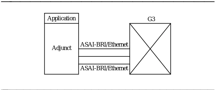
Additional Configurations
bbbbbbbb
Figures 2-2 to 2-4 show additional ASAI configurations supported in Generic 3.The applications supported for these configurations are the same as those previously described in this section.
bbbbbbbbbbbbbbbbbbbbb
ASAI-BRI/Ethernet ASAI-BRI/Ethernet Adjunct
Application G3
bbbbbbbbbbbbbbbbbbbbbbbbbbbbbbbb
Figure 2-2. Multiple Link — Single Processor Configuration
ASAI and Supported Applications
bbbbbbbbbbbbbbbbbbbbbbbbbbbbbbbbbbbbbbbbbbbbb
bbbbb
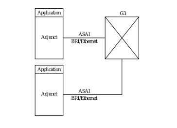
bbbbbbbbbbbbbbbbbbbbb
Adjunct Application
ASAI BRI/Ethernet BRI/Ethernet
ASAI Application
Adjunct
G3
bbbbbbbbbbbbbbbbbbbbbbbbbbbbbbbb
Figure 2-3. Single Link — Multiple Processors Configuration
ASAI and Supported Applications
bbbbbbbbbbbbbbbbbbbbbbbbbbbbbbbbbbbbbbbbbbbbb
bbbbb
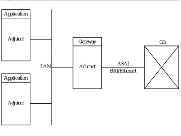
bbbbbbbbbbbbbbbbbbbbb
LAN Application
Adjunct Application
Adjunct
Adjunct Gateway
ASAI BRI/Ethernet
G3
bbbbbbbbbbbbbbbbbbbbbbbbbbbbbbbb
Figure 2-4. Single Link — Gateway/Server Configuration
Figure 2-4 shows multiple adjuncts communicating with a Generic 3 switch via a single ASAI link. Each adjunct is independent of each other and the ASAI link is managed by a single adjunct. This adjunct serves as the ‘‘gateway’’ between the data Local Area Network (LAN) environment and protocols and the voice
ASAI and Supported Applications
bbbbbbbbbbbbbbbbbbbbbbbbbbbbbbbbbbbbbbbbbbbbb
bbbbb
bbbbbbbbbbbbbbbbbbbbb
LAN Application
Adjunct Gateway ASAI VRU
Voice lines
G3 ASAI
BRI/Ethernet
bbbbbbbbbbbbbbbbbbbbbbbbbbbbbbbb
Figure 2-5. ASAI Integration with a VRU Configuration
In Figure 2-5 the application shown uses ASAI together with voice response services to control calls. For example, incoming calls might terminate on the VRU where VRU software collects additional information. Using this information the application might then make an ASAI request to transfer the call to its final destination.
NOTE:
bbbbbbbbbbbbbbbbbbbbbbbbbbbbbbbbbbbbbbbbbbbbb
bbbbb
bbbbb
Event Reporting and U-Abort
Capabilities
3
bbbbbbbbbbbbbbbbbbbbbbbbbbbbbbbbbbbb
Introduction
bbbbbbbb
Common capabilities are those capabilities used by more than one capabilitygroup. There are two common capabilities: Event Reporting and U-Abort (User Abort).
This chapter describes these capabilities and the capability groups where they are present.
Event Reporting Capability
This capability is used by the switch to send call-related information to an adjunct. For example, if a user makes a call from his or her telephone, event reports are sent to an adjunct regarding the call, provided that event reporting has been requested for this particular telephone or call.
NOTE:
Event reporting does not generate screen-formatted or hardcopy reports. Event reporting, for the purposes of ASAI, simply means that call information is provided to an adjunct by the switch. Event Reports are
‘‘informational only.’’ To control a call, an application must use call control capabilities.
U-Abort Capability
Event Reporting and U-Abort Capabilities
bbbbbbbbbbbbbbbbbbbbbbbbbbbbbbbbbbbbbbbbbbbbb
bbbbb
Event Reports
bbbbbbbb
Capability Groups and Event Reporting
bbbbbbbbbbbbbbb
The Event Reporting capability can be invoked from the following capability groups:
Call Control Capability Group
Domain (Station or ACD Split) Control Capability Group Notification Capability Group
See Chapters 4, 5, and 6, respectively, for discussions of these capability groups.
An administrable option called ‘‘Event Minimization’’ is available for each ASAI link. This option may be used when event reports would normally be sent on multiple associations, but the adjunct does not need to see more than one. Typically, these event reports are identical except for the association they are sent over (for example, call control, domain control, active notification). Some applications discard duplicate events, so in this case, there is no point in sending them across the ASAI link. When enabled, this option allows only a single such event to be sent. The selection of the association on which the event will be sent is based on association precedence as follows: active notification (if enabled), call control (if enabled), domain control (if enabled).
The Station form is used to change this option. The new option settings take effect the next time the ASAI link is activated.
Call-Related Event Reporting
bbbbbbbbbbbbbbb
The adjunct receives call-related event reports from the switch for the following call types:
Controlled Calls — Calls controlled by the adjunct via the Call Control Capability Group
Domain-Controlled Calls — Calls controlled by the adjunct via the Domain (in other words, station) Call Control Capability Group
Event Reporting and U-Abort Capabilities
bbbbbbbbbbbbbbbbbbbbbbbbbbbbbbbbbbbbbbbbbbbbb
bbbbb
Non-Call-Related Event Reporting
bbbbbbbbbbbbbbb
The event reports mentioned previously were all related to a specific call. An event report that is not directly related to a specific call can also be generated. When an agent logs out of a split/skill that is under Domain (ACD split) Control, a Logout Event Report is generated. Starting with G3V4, a Login Event Report is generated when an agent logs into this type of split. These reports are
discussed in detail later in this section.
Information Flow
bbbbbbbbbbbbbbb
The adjunct does not respond to event reports. (An adjunct is not required to send a response when an Event Report is received.)
Parameters
bbbbbbbbbbbbbbb
event_name [mandatory] Specifies the event being reported
item_value_list [optional] Contains a list of items and their values for the event being reported
Event Reports and Corresponding Items
bbbbbbbbbbbbbbb
Every event report issued by the Generic 3 switch contains pieces of information that, individually, are called items. Item combinations contain information about the specific event being reported. The following table presents the different event reports and the corresponding items available to the Event Reporting capability.
In general, event reports are not sent for split or vector announcements or attendant group 0.
bbbbbbbbbbbbbbbbbbbbbbbbbbbbbbbbbbbbbbbbbbbbbbbbbbbbbbbbbbbbbbbbbbbbbbbbbbbbbbb
Event Report Items Provided with Each Event Report
bbbbbbbbbbbbbbbbbbbbbbbbbbbbbbbbbbbbbbbbbbbbbbbbbbbbbbbbbbbbbbbbbbbbbbbbbbbbbbb
Calling Party number (CPN/BN) or
Trunk Group number and Trunk Group Member number — only provided if the Calling Party number is unavailable Called Party number (originally dialed number)
Cause
Event Reporting and U-Abort Capabilities
bbbbbbbbbbbbbbbbbbbbbbbbbbbbbbbbbbbbbbbbbbbbb
bbbbb
bbbbbbbbbbbbbbbbbbbbbbbbbbbbbbbbbbbbbbbbbbbbbbbbbbbbbbbbbbbbbbbbbbbbbbbbbbbbbbbbbbbbbbbb
Event Report Items Provided with Each Event Report
bbbbbbbbbbbbbbbbbbbbbbbbbbbbbbbbbbbbbbbbbbbbbbbbbbbbbbbbbbbbbbbbbbbbbbbbbbbbbbbbbbbbbbbb
Domain (ACD split associated with the call — if any) User to User Information (UUI)
Reason for Redirection
Alerting, cont’d.
Called Party number
Connected Party number (answering party number) Call_id
Party_id
Cause (Special Information Tone [SIT] or Answering Machine Detection [AMD] — if any)
Answered
Called Party number (busy number) Call_id
Cause
Busy/Unavailable
Calling Party number (conference initiator party number) Called Party Number (newly added party number) Other Call_id
Resulting Call_id
Party_id List (up to six party_ids) Extension List (up to six extensions)
Event Reporting and U-Abort Capabilities
bbbbbbbbbbbbbbbbbbbbbbbbbbbbbbbbbbbbbbbbbbbbb
bbbbb
bbbbbbbbbbbbbbbbbbbbbbbbbbbbbbbbbbbbbbbbbbbbbbbbbbbbbbbbbbbbbbbbbbbbbbbbbbbbbbbbbbbbbbbbb
Event Report Items Provided with Each Event Report
bbbbbbbbbbbbbbbbbbbbbbbbbbbbbbbbbbbbbbbbbbbbbbbbbbbbbbbbbbbbbbbbbbbbbbbbbbbbbbbbbbbbbbbbb
Call Offered to Domain,
cont’d. Called Party number (DNIS)
Call_id
Item indicator (User-Entered Information — contains up to 16 digits from the most recent Collect Digits vector step) Lookahead Interflow Information
Domain (ACD split or VDN) User to User Information (UUI) Flexible Billing
Call_id Party_id
Calling Party number Called Party number Party extension
Call Originated
Call_id
Call Redirected
Calling Party Number (transfer initiator party number) Called Party Number (transferred party number) Other Call_id
Resulting Call_id
Party_id List (up to six party_ids) Extension List (up to six extensions)
Call Transferred
Calling Party number (CPN/BN) or
Trunk Group number and Trunk Group Member number — only provided if the Calling Party number is unavailable Called Party number (DNIS)
Event Reporting and U-Abort Capabilities
bbbbbbbbbbbbbbbbbbbbbbbbbbbbbbbbbbbbbbbbbbbbb
bbbbb
bbbbbbbbbbbbbbbbbbbbbbbbbbbbbbbbbbbbbbbbbbbbbbbbbbbbbbbbbbbbbbbbbbbbbbbbbbbbbbbbbbbb
Event Report Items Provided with Each Event Report
bbbbbbbbbbbbbbbbbbbbbbbbbbbbbbbbbbbbbbbbbbbbbbbbbbbbbbbbbbbbbbbbbbbbbbbbbbbbbbbbbbbb Party_id Cause Connected, cont’d. Call_id Party_id Progress Indicator Cut-Through
Connected Party number (dropped number) Call_id
Party_id Cause
User to User Information (UUI)
Disconnect/Drop
Digits
Entered Digits
Connected Party number (number that placed the call on hold)
Call_id Party_id
Hold
Work Mode
Agent Physical Extension Agent Logical Extension
Login
Agent Physical Extension Agent Logical Extension
Logout
Called Party number (DNIS)
Event Reporting and U-Abort Capabilities
bbbbbbbbbbbbbbbbbbbbbbbbbbbbbbbbbbbbbbbbbbbbb
bbbbb
bbbbbbbbbbbbbbbbbbbbbbbbbbbbbbbbbbbbbbbbbbbbbbbbbbbbbbbbbbbbbbbbbbbbbbbbbbbbbbbb
Event Report Items Provided with Each Event Report
bbbbbbbbbbbbbbbbbbbbbbbbbbbbbbbbbbbbbbbbbbbbbbbbbbbbbbbbbbbbbbbbbbbbbbbbbbbbbbbb
Connected Party number (number that reconnected to the call)
Call_id Party_id
Reconnected
Called Party number (default unknown) Call_id
Cause
Reorder/Denial
Event Reporting and U-Abort Capabilities
bbbbbbbbbbbbbbbbbbbbbbbbbbbbbbbbbbbbbbbbbbbbb
bbbbb
Alerting Event Report
The switch sends the Alerting Event Report for monitored, controlled, and domain-controlled calls when the following events occur:
The originator of a switch-classified call1 is an on-PBX station, and ringing
or zip tone is started.
When a call is redirected to an off-PBX station and the ISDN ALERTing message is received from an ISDN-PRI facility.
When a switch-classified call is trying to reach an off-PBX station, and the call classifier detects either precise, imprecise, or special ringing.
When a switch-classified or user-classified call is placed to an off-PBX station, and the ALERTing message is received from the ISDN-PRI facility.
NOTE:
When a classifier and an ISDN-PRI facility both report alerting on a switch-classified call, then the first occurrence generates an Alerting Event Report; succeeding reports are not reported by the switch. Consecutive Alerting Event Reports are possible in the following cases:
A station is alerted first and the call goes to coverage; an Alerting Event Report is generated each time a new station is alerted.
A principal and its bridging users are alerted; an Alerting Event Report is generated for the principal and for each bridged station alerted.
A call is alerting a Terminating Extension Group (TEG); one report is sent for each TEG member alerted.
A call is alerting a Personal Central Office Line (PCOL); one report is sent for each PCOL member alerted.
A call is alerting a coverage/answer point; one report is sent for each alerting member of the coverage answer group.
A call is alerting a principal with SAC active; one report is sent for the principal and one or more are sent for the coverage points.
Event Reporting and U-Abort Capabilities
bbbbbbbbbbbbbbbbbbbbbbbbbbbbbbbbbbbbbbbbbbbbb
bbbbb
Report Items
The following is a list of items provided with this report:
Calling Party number
For outgoing calls over PRI facilities — ‘‘calling number’’ from the ISDN SETUP message.
For outgoing calls over non-PRI facilities or on-PBX calls — locally originating extension.
For incoming call over PRI facilities — ‘‘calling number’’ from the ISDN SETUP message.
For incoming calls over non-PRI facilities, the calling party number is generally not provided. In this case, the Trunk Group number is provided instead.
For calls originated at a bridged call appearance — the principal’s extension.
For incoming DCS calls, if the DCS calling party information is available to the switch (if a station with a display gets it), this information is also made available to ASAI. Otherwise, the calling party information is provided as the default.
Trunk Group number/Trunk Group Member number
The Trunk Group number and Trunk Group Member number are only provided if the Calling Party number is unavailable.
Called Party number (DNIS)
For outgoing calls over PRI facilities, the called number as in the SETUP message.
For outgoing calls over non-PRI facilities, the called number is the default trunk value (#####).
For incoming calls over PRI facilities, the called number is the one provided in the SETUP message.
For incoming calls over PRI facilities to a VDN that does lookahead interflow on calls, if the lookahead interflow attempt fails, the called number provided is the principal extension of the dialed number. If the interflow attempt is successful, the Called Party number is provided as the default.
For incoming calls over non-PRI facilities, the called number is the principal extension (may be a group [TEG, hunt group, VDN] extension)2
aaaaaaaaaaaaaaaaaaa
Event Reporting and U-Abort Capabilities
bbbbbbbbbbbbbbbbbbbbbbbbbbbbbbbbbbbbbbbbbbbbb
bbbbb
For incoming calls to PCOL, the called number is the default extension value (*****).
For incoming calls to a TEG (principal) group, the TEG group extension is provided.
For incoming calls to a principal with bridges, the principal’s extension is provided.
Connected Party number (alerting party number)
For outgoing calls over PRI or non-PRI facilities — the default trunk value (#####)
For incoming calls — locally alerting extension (primary extension for TEGs, PCOLs, bridging). If the party being alerted is on the switch, then the extension of the party being alerted is passed.
Call_id This switch-assigned call identifier is used to associate event reports to calls and to identify a call the adjunct wants to control. The call identifier is unique within the switch.
Party_id The switch-assigned identifier that uniquely identifies a party on a call. The switch provides the identifier and the adjunct should retain it for future operations. The party identifier is unique within the call_id.
User to User Information
If UUI is stored with the call, then that UUI is included in the Alerting Event Report. This applies to UUI that originated in an ISDN PRI/BRI SETUP message; in an ISDN
DISCONNECT message; or in an ASAI Route Select, 3rd Party Make Call, or 3rd Party Auto-Dial message.
Reason for Redirection
The reason the call has been presented and is alerting at a domain-controlled station. Only applies to calls redirected by the switch or by ASAI from the original destination.
NOTE:
Event Reporting and U-Abort Capabilities
bbbbbbbbbbbbbbbbbbbbbbbbbbbbbbbbbbbbbbbbbbbbb
bbbbb
Answered Event Report
The Answered Event Report is only sent for the destination of a switch-classified call, as follows:
When a switch-classified call is placed to an on-PBX station and the station has answered the call (picked up handset or connected after zip tone).
When a switch-classified call is placed to an off-PBX destination and an ISDN CONNect message is received from an ISDN-PRI facility.
When a switch-classified call is placed to an off-PBX destination and the call classifier detects an answer, an answering machine, or a Special Information Tone (SIT) administered to answer. For specific SIT and AMD values, refer to Table 4-2, Detected SITs, in Chapter 4, ‘‘ASAI and Call Control.’’
NOTE:
Only one Answered Event Report is possible for a call.
Report Items
The following is a list of items provided with this