EFFECT OF LIGHTING DIFFERENCE IN RECONSTRUCTION OF THREE DIMENSIONAL DENSE MODEL USING CLOSE RANGE PHOTOGRAMMETRY
RAIMI BIN MOHAMED FADZEL
A project report submitted in partial fulfilment of the requirements for the award of the degree of
Master of Science (Geomatic Engineering)
Faculty of Geoinformation and Real Estate Universiti Teknologi Malaysia
In the name of God, most Gracious, most Compassionate
I dedicate my project report work to Allah swt, my family and friends. A special feeling of gratitude to my loving parents, Mohamed Fadzel Bin Bien whose words of encouragement and push for tenacity ring in my ears, and Masanah Sa Binti Abdullah
my beloved mother always be my side throughout the process and your love. My Brothers, Zulhanan Bin Mohamed Fadzel, Mohd Hadari Bin Mohd Fadzel, my sister, Sakinah Binti Mohamed Fadzel and lastly my youngest brother Muhammad Khairul Ezy
Bin Mohamed Fadzel.
I also, dedicate this project report to my friends who have give lots of ideas and excellent opinion along the process. I will always appreciate all they have done and helping me to achieve the project objectives. And also I appreciate to everyone who was
ACKNOWLEDGEMENT
V
ABSTRACT
VI
ABSTRAK
VII
TABLE OF CONTENTS
CHAPTER TITLE PAGE
DECLARATION ii
DEDICATION iii
ACKNOWLEDGEMENTS iv
ABSTRACT v
ABSTRAK vi
TABLE OF CONTENTS vii
LIST OF TABLES x
LIST OF FIGURES xi
LIST OF ABBREVIATIONS xii
LIST OF SYMBOLS xiv
1 INTRODUCTION 1
1.1 Introduction 1
1.2 Problem Background 3
1.3 Problem Statements 4
1.4 Objectives of Study 5
1.5 Scope of Study 6
1.6 A Brief Note on the Methodology 7
1.7 Significant of Study 9
VIII
2 LITERATURE REVIEW 11
2.1 Introduction 11
2.2 Photogrammetry 12
2.2.1 Technique and Instrument used in Photogrammetry 12
2.2.1.1 Camera 13
2.2.1.2 Photo Control 16
2.2.1.3 Processing Software 17
2.2.1.4 Photogrammetry Technique 19
2.2.2 Digital Close Range Photogrammetry 21
2.2.3 Laser Scanning 22
2.3 Radiometric Factors 23
2.3.1 Resolution 24
2.3.2 Noise 24
2.4 Geometric Factors 27
3.4.1 Camera Calibration 27
2.5 3D model evaluation 28
2.6 Lighting 30
2.7 Summary 32
3 METHODOLOGY OF RESEARCH 33
3.1 Introduction 33
3.1 Research Workflow 34
3.2 Project Planning 35
3.2.1 Area, Software and Instrumentation 36
3.2.1.1 Area of Study 36
3.2.1.2 Processing Software 38
3.2.1.3 Instrumentation 39
a) Camera 39
b) Laser Scanner 43
IX
3.2.1 Camera Calibration 46
3.2.2 Technique 48
3.3 Data Processing 48
3.3.1 3D Model and Image Analyzing 50
3.4 Data Analysis and Finding 50
3.5 Summary 51
4 RESULT AND ANALYSIS 53
4.1 Introduction 53
4.2 Camera Calibration 54
4.3 Three Dimensional (3D) Generation 56
4.3.1 Number of Images against Number of 3D points 57
4.3.1.1 Outdoor Scenario 57
4.3.1.2 Indoor Scenarios 59
4.3.2 3D models result 60
4.3.2.1 Outdoor Scenarios 60
4.3.2.2 Indoor Scenarios 63
4.4 Luminosity Analysis 64
4.4.1 Outdoor Scenarios 66
4.4.2 Indoor Scenarios 69
4.5 Image Analysis 71
4.6 Footprint measurement 73
4.7 Summary 75
5 DISCUSSION AND RECOMMENDATION 76
5.1 Introduction 76
5.2 Discussion 77
5.3 Recommendation 78
5.4 Summary 78
X
LIST OF TABLES
TABLE NO. TITLE PAGE
2.1 System requirement for menci software 18
2.2 System requirement for PhotoModeler software 19
2.3 Classification of laser scanner 23
2.4 Comparison between Laser Scanning and Photogrammetry 29
3.1 Scenario and number of images 37
3.2 SONY Cybershot DSC-F828 full specifications 40 3.3 Non-contact 3D digitizer VIVID 910 full specifications 44
4.1 Camera Calibration Result. 56
4.2 The number of point cloud generated. 57
4.3 The number of point cloud generated for indoor scenarios 59
4.4 Model Comparison 61
4.5 Indoor 3D dense models 63
4.6 The image and luminosity histogram 67
4.7 Indoor result comparison 69
4.8 Footprint measurement comparison 74
XI
LIST OF FIGURES
FIGURE NO. TITLE PAGE
1.1 Research Workflow 8
2.1 The camera obscura concept 13
2.2 Hasselblad MKWE 14
2.3 Non metric camera, Sony DSC-F828 16
2.4 RAD Target system 17
2.5 RAD is placed around the object 17
2.6 The example of overlapping cases. (a) No overlap case, (b) Insufficient overlap case and (c) Sufficient overlap case
22
2.7 Resolution against image detail 24
2.8 De-noising process 26
2.9 Comparison between different ISO used. ISO 100 (left), ISO 1600 (middle) and comparison for small section (right)
27
2.10 (a) Single Sheet and (b) multi sheet camera calibration 28
2.11 Electromagnetic Spectrum 31
3.1 The main procedure in this research 34
3.2 Project planning process 35
3.3 Single Sensor imaging: (a) Mosaic-like greyscale CFA image (b) color variant of the CFA image (c) Demosaicked full-color image
XII
3.4 The different RGB arrangement for CFA used 42
3.5 VIVID 910 and Triangulation approach 43
3.6 The process of data collection 45
3.7 The camera calibration workflow 47
3.8 Data processing steps 49
3.9 Data analysis and finding process 51
4.1 Analysis and Finding flowchart 53
4.2 Camera orientation and position 55
4.3 Calibration process is running 55
4.4 Number of Image and 3D point for outdoor scenarios 58
4.5 Number of Image and 3D point generated 60
4.6 Create Dense Surface setting (Outdoor) 61
4.7 The RMSE value against the number of images 62
4.8 Create dense surface setting (indoor) 63
4.9 RMSE value against number of images 64
4.10 The brightness histogram 65
4.11 The cloudy image (Left) and the clearly sky image (right) 71
4.12 The Luminosity histogram comparison 72
4.13 Indoor image (left) and outdoor image (right) 72
XIII
LIST OF ABBREVIATIONS
CRP Close Range Photogrammetry
CCD Charge coupled deviced
CMOS Complementary metal oxide semiconductor
RAD Ringed Automatically Detection
UAV Unmanned Aerial Vehicle
DSM Dense Surface Model
DSLR Digital Single Lens Reflex
SNR Signal and Noise Ratio
ISO International Standard Organization
CFA Color Filter Array
CFM Color Filter Mosaic
RGBE Red, Green, Blue and Emerald
EMCCD Electron Multiplied Charge Coupled Device
ICCD Intensified Charge Coupled Device
XIV
LIST OF SYMBOLS
1
CHAPTER 1
INTRODUCTION
1.1 Introduction
Photogrammetry is a combination of three Greek’s words “photos” or “phot”
2
used in variety type of industries for example in archeology which used to modeling the pottery, artifacts of culture heritage, statue and building (Kadobayashi et al, 2004). Furthermore, in movie industry, these techniques are quite popular for instance, constructing 3D model of character of animation and real motion picture. Last but not least, this techniques is also used in medical industry, architecture industry and engineering as well (Yilmaz et al., 2008).
The development of science and technology in world of photogrammetry served lots of advantages to the photogrammetry people. The improvement can be seen in form of instrumentation, methodology and processing software and hardware. They have tried to create new approach to resolve the problems faced by photogrammetry people. This phenomenon are due to the demand of high data quality, accuracy and precision and also reduce human interfere during the processing. The quality of data is most critical aspect in surveying and in photogrammetry as well. The data recorded is processed to generate 3D model by using 3D modeling software, and then documentation process for all the information, data and result. In archeology industry, all types of data collected related to the artifact must be put in one document for further analysis and interpretation (Barsanti
et al, 2014).
3
Camera has been used so many years as one of the equipment in recording scenes, surfaces or objects. Before the digital camera has been introduced in public, the photographer were used conventional camera which depends entirely on chemical and mechanical process and do not use electricity to operate. The new technology was totally changed how the visual information is recorded. Nowadays, digital camera is widely used by photogrammetry people. It is consists of build-in computer and records the images in an electronic form or digitally. Moreover, digital camera consists of sensor that converts light into electrical charge. The light is reflected on the surfaces of the objects before reach to the digital camera’s sensor (Karim et al, 2004). There are multiple types of sensors for example Couple Charge Device (CCD), Complementary Metal Oxide Semiconductor (CMOS) and more. These sensors consist of tiny light-sensitive diode known as photosites. For example, a 2.1 megapixel camera has approximately 2 100 000 photosite on the CCD. In other hand, resolution is the amount of detail that the camera can capture and it is measured in pixel. So, the more pixel camera has, the more detail and clear of image can be. The example of digital cameras available in the market are Sony Alpha 7 II, Richo EG-30, Leica x( Type 113), Canon PowerShot SX60 HS, Nikon D750, Panasonic Lumix DMC-LX100, Samsung NX1 and more.
1.2 Problem Background
4
affect the geometry and radiometric information and also causing some problems during the processing phase (Blizard, 2013). Therefore, he was suggested to provide an adequate of illumination exposed surrounding the object during capturing the images activity, so the high-detail, sharp and flat imagery can be produced.
In addition, one of the steps in 3D model reconstruction process is locating the image target point or reference. The sharp and clear images are help to locate the target point accurately. Therefore, high resolution camera allows sharper and more detail of the images, which improves the resolvability of the target point. Besides, external light source is used to provide enough illumination of the object (Jack, 2003). Indoor and outdoor activities are also can affect the result and images quality because of the different in source of lighting.
Outdoor activity is depends on the sun light. The sunlight might produce shadows and different brightness between the images. The formation of shadows are due to when the sun is not on top of the object and the brightness is different because of the cloud is covering the sky during the capturing image. Meanwhile, indoor activity is using artificial source of lighting for examples bulb, fluorescent and others. The number of bulb and the distance between the object provides difference illumination to the object. It is important to ensure all the images have similar brightness and shadows. Otherwise, overlapping the texture process can generate inconsistent texture on the model (Radoservic, 2010).
1.3 Problem statements
5
1. Lighting is one of the factors that affecting the quality of images and it is used in reconstruction 3D dense model. In order to simulate the illumination and brightness at the real cases, the difference of lighting models is used. Then, multiple overlapping images of an irregular artificial object are captured by using consumer grade digital camera at different position. Does 3D dense surface can be established from these images?
2. Quality of images is important in image interpretation and measurement process which to be identified from its form, brightness or color distribution for every image point, values in the form of radiometric information and geometric information (position in image) can be obtained. This requires measurement systems with appropriate geometric and optical quality. So, what are the relationship and effects to the radiometric and geometric information of images and output (model) when differences of lightning are used?
3. New methods and equipments have been introduced with high technology implied to fulfill the demand for high precision and accuracy of the output. For example, laser scanning technique, this technique is provided more accurate result compare with conventional method in reconstruction of 3D model (Kadobayashi et al., 2004). Therefore, which 3D models are more accurate by comparing the 3D model obtained by laser scanning technique?
1.4 Objectives of study
There are three objectives for this study and they are:
1. To reconstruct 3D dense models from difference source of illumination.
2. To study the accuracy of 3D models formed by using difference source of illumination
6
1.5 Scope of Study
This study is covered only small irregular artificial object and size which is to simulate the small artifact goods such as poetry, human footprint, tombs and more. The approximate object’s dimension used in this study is 27 cm width, 36 cm long and 10 cm height and the size is easy to handle. It is because the object is move from one place to another place. Moreover, to make sure the object use is similar throughout the study, the object was made up from less fragile medium and fix shape such as cement. Cement is one of the suitable medium to create artificial object because, the object would not able to change whatever condition and place.
The process of data collection was planned to do at two different places; indoor and outdoor space at near to Faculty Geoinformation and Real Estate, Universiti Teknologi Malaysia, Skudai Johor Baharu, Malaysia (1°33'37.1"N 103°38'13.5"E). Based on article from Malaysia Meteorological Department website, on the average, Malaysia received about six hours of sunshine per day. Therefore, the light intensity is different at different country and continent based on the latitude and longitude but this is not the only factor that affecting the light intensity (Paul Burgess, 2009). The data collection for outdoor activity is collected within that period of time. Meanwhile, indoor activity is fully dependant on the artificial lighting and it is explained in chapter 3 in this thesis.
7
1.6 A Brief Note on the Methodology
In surface, this study is aims to manipulate the condition surrounding the object especially the lighting. The differences of illumination either indoor or outdoor would give effect on the reconstruction of 3D model, radiometric information and geometry. Therefore, the irregular artificial object is converted into 3D model by using CRP procedure. Multiple of images are captured surrounding the object at different camera position to ensure 60 % overlapping or more of images can be achieved.
The software used to create 3D dense model is PhotoModeler scanner Software. This software is able to determine root mean square error, total error, residual and precision values of projects. In order to determine the accuracy of the project, laser scanning technique is used and apply on the similar object before 3D model can be obtained. And then, the analysis of the model is made to identify the accuracy of the project. Last but not least, the geometrical assessment is performed by comparing the 3D model from CRP method, laser scanning method and direct method.
8
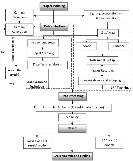
Figure 1.1: Research Methodology Workflow No
Yes Laser Scanning
Technique CRP Technique
Project Planning
Data collection Camera
Calibration Camera Selection
Site/ Area
Indoor Outdoor
Lighting preparation and timing selection
Instruments setup
Images Recording
Images storing and grouping Instruments setup
Object Scanning
Data Transfer/storing
Data Processing
Processing Software (PhotoModeler Scanner)
Modeling
Result
Laser scanning result/ model
CRP result/ models
Data Analysis and Finding
Accept the
9
1.7 Significant of Study
This research is trying to investigate the effect of lighting towards the radiometric information and geometric of 3D model by using CRP technique. Since, the photogrammetry has been used in multiple types of industries, so the environment might be different from one another. What I mean, the brightness and illumination of site area where the image-based photogrammetric technique is applied. Moreover, this research is trying to give idea on lighting selection and suitable period where the sun light position and then it may reduce the shadow and brightness to get the good quality of images.
A part from that, this study is applied laser scanning technique and creates the 3D model. Most of researcher did mention the advantages of laser scanning technique in creating 3D model. Therefore, in this study, this technique is set as a benchmark of the result obtained from CRP method to see which models created is most accurate, and then identify which lighting model gives better result/illumination to the object.
Last but not least, the images captured with different of lights produce different of intensity value on the images. Therefore, by using luminosity histogram analysis illustrated the relation between intensity value and images of different exposure. Moreover, another aspect is evaluated such as luminosity histogram, the image analysis and the relationship between the number of image and point cloud generated.
1.8 Thesis Outline
79
REFERENCES
a Journal
Abd. Manan Samad, Norazlini Hassan Sauri, Muhd Asyraf Hamdani et al (2012).
Kellie’s Castle Facade Recording Using Digital Close-range Photogrammetry.
IEEE 8th International Colloquium on Signal Processing and its Applications.
Anthony P Lyons, T. Akal and E. Pouliquen (1998). Measurement of seafloor
Roughness with Close Range Digital Photogrammetry. OCEANS ’98
Conference Proceeding (volume 1).
Armin Grun, Fabio Remondino and Li Zhang (2004). Photogrammetric Reconstruction
Of The Great Buddha Of Bamiyan, Afghanistan. The Photogrammetric Record
19(107): 177–199
Benjamin Ummenhofer and Thomas Brox. Pattern Recognition: Dense 3D
Reconstruction with Hand-Held Camera. Springer Berlin Heidelberg. pp 103-112; 2012
C.Mythili and V. Kavitha (2011). Efficient Technique for Color Image Noise Reduction.
The Research Bulletin of Jordan ACM, Vol 11(111)
Celestino Ordonez, Belen Riveiro, Pedro Arias and Julia Armesto (2009) Application of Close Range Photogrammetry to Deck Measurement in Recreational Ships.
SENSOR ISSN 1424- 8220
Cengishan Ipuker(2010). The Reason of Changing The Name to “Geomatics”. FIG Congress 2010 Facing the Challenges – Building the Capacity Sydney, Australia, 11-16 April 2010
80
Daniel Carneiro Da Silva (2006). Non-Metric Digital Camera Images versus High Resolution Satellite Images in Regions with High Cloudiness. Shaping the Change XXIII FIG Congress Munich, Germany, October 8-13.
D. Mihajlović, M. Mitrović, Ž. Cvijetinović and M. Vojinović (2008). Photogrammetry Of Archaeological Site Felix Romuliana At Gamzigrad Using Aerial Digital Camera And Non-Metric Digital Camera. The International Archives of the Photogrammetry, Remote Sensing and Spatial Information Sciences. Vol. XXXVII. Part B5. Beijing 2008
Dimitar Jechev (2004). Close-Range Photogrammetry With Amateur Camera. Commission V, WG V/4
E. Sree Devi And B. Anand (2014). Adaptive Color Filter Array Interpolation Algorithm Based On Hue Transition And Edge Direction. Journal of Theoretical and
Applied Information Technology 31st January 2014. Vol. 59 No.3
F.A. van den Heuvel and R.J.G.A. Kroon (1992). Digital Close-Range Photogrammetry Using Artificial Targets. ISPRS.
George E. Karrasa and Dionyssia Mavrommati (2001).Simple Calibration Techniques
For Non-Metric Cameras. CIPA International Symposium, Potsdam, September
18-21, 2001
Goran Radoservic (2010). Laser Scanning Versus Photogrammetry Combined with Manual Post-modeling in Stecak Digitization. Proceedings of CESCG 2010: The14th Central European Seminar on Computer Graphics
Goran Radosevic (2010). Laser Scanning Versus Photogrammetry Combined with Manual Post-modeling in Stecak Digitization. Proceedings of CESCG 2010: The14th Central European Seminar on Computer Graphics
H.Murat Yilmaz, Murat Yakar And Ferruh Yildiz (2008). Digital Photogrammetry In Obtaining Of 3d Model Data Of Irregular Small Objects. ISPRS.
Habil. András Majoros (2011). Artifical Lighting Lecture Note. Budapest University of Technology and Economics Faculty of Architecture Department of Building Energetics and Services
Heinz Ruther, Julian Smit and Donatius Kamamba (2012). A Comparison of Close-Range Photogrammetry to Terrestrial Laser Scanning for Heritage
81
Huiping, H., Bingfang, W., and Jinlong, F., 2003. Analysis to the Relationship of Classification Accuracy Segmentation Scale Image Resolution, Proceedings of IEEE 2003 International Geoscience and Remote Sensing Symposium,
Ismail Ma’arof, Siti Zubaidah Bahari, Zulkiflee Abd Latif et al.(2013). Image Based Modeling and Documentation of Malaysian Historical Monuments Using Digital
Close-Range Photogrammetry (DCRP). IEEE International Conference on
Control System, Computing and Engineering
Jack Leifer (2003). A Close-Range Photogrammetry Laboratory Activity for Mechanical Engineering Undergraduates. 33rd ASEE/ IEEE Frontier in Education
Conference.
Jana Visnovcova, Armin Gruen and Li Zhang (2001). Image-Based Object Reconstruction And Visualization For Inventory Of Cultural Heritage.
http://www.researchgate.net/
Joaquim Salvi, Xavier Armangu and Joan Batlle (2000). A comparative review of camera calibrating methods with accuracy evaluation. Pattern Recognition 35 (2002) 1617–1635
Joyce Farrella, Mike Okinchab, Manu Parmarac, and Brian Wandellac (2010). Using visible SNR (vSNR) to compare the image quality of pixel binningand digital resizing. Proc. SPIE 7537, 75370C.
Michael Zeman And B. Blakeman (1984). Terrestrial Photogrammetric Survey of Arltunga Historic Reserve, Northern Territory. Australian Historical Archaeology, 2
Mike Craig (2002). Vertical Aerial Photograph. In Papp, E. (Editor), 2002, Geophysical and Remote Sensing Methods for Regolith Exploration, CRCLEME open file report 144, pp 1-5.
Mohd. Faizury Abol Hassan, Ismail Ma'arof and Abd. Manan Samad (2014). Assessment of Camera Calibration towards Accuracy Requirement. IEEE 10th International Colloquium on Signal Processing & its Applications (CSPA2014), 7 - 9 Mac. 2014, Kuala Lumpur, Malaysia
Muhd Safarudin Chek Mat, Jezan Md Diah, Mokhtar Azizi Mohd Din and Abd. Manan Samad., (2014). Data Acquisition and Representation of Leaves using Digital Close Range Photogrammetry for Species Identification. IEEE 5th Control and System Graduate Research Colloquium
82
Presentation to Continuous Cover Forestry Group (Ccfg) Scientific Meeting 29 September 2009, Westonbirt Arboretum, Gloucestershire.
Reiko Kadobayashi, Nobuo Kochi and Hitoshi Otani et al.,(2004). Comparison And Evaluation Of Laser Scanning And Photogrammetry And Their Combined Use For Digital Recording Of Cultural Heritage.XXth ISPRS CongressTechnical Commission V
Rastislav Lukac and Konstantinos N. Plataniotis (2005). Color Filter Arrays: Design and Performance Analysis.IEEE Transactions on Consumer Electronics, Vol. 51, No. 4,
Rohit Verma and Jahid Ali (2013). A Comparative Study of Various Types of Image Noise and Efficient Noise Removal Techniques. International Journal of
Advanced Research in Computer Science and Software Engineering Volume 3, Issue 10, October 2013
Sara Gonizzi Barsanti, Fabio Remondino and Domenico Visintini (2014). Critical factors and guidelines for 3D surveying and modeling in Cultural Heritage. International Journal of Heritage in Digital Era, vol 3 number 1.
Thomas Luhmann, Heidi Hastedt, Werner Tecklenburg (2006). Modelling Of Chromatic Aberration for High Precision Photogrammetry. IAPRS Volume xxxvi, Part 5, Dresden 25-27 September 2006
V. Kaufmann and R. Ladstadter (2008). Application Of Terrestrial Photogrammetry For Glacier Monitoring In Alpine Environments. Commission VIII, WG VIII/8 Vesna Stojaković (2008). Terrestrial Photogrammetry And Application To Modeling
Architectural Objects. Architecture and Civil Engineering Vol. 6, No 1, 2008, pp. 113 – 125
William C. Haneberg (2008). Experience using close range terrestrial digital
photogrammetry for 3-D rock slope modeling and discontinuity mapping in the United States. Springerlink
Xie Hong-Quan and Jia Hai Hu (2010). The Development of 3D Laser Scanning Technique in and its Application in Land Reclamation. ISPRS Journal
83
b) Website Article/ Technical Report/ Paper
Anahid A. Behrouzi, Rui Li (2012). Instruction Manual: Photogrammetry As A Non-Contact Measurement System In Large Scale Structural Testing. University of Illinois
Brandon Blizard (2013).The Art of Photogrammetry: How to take your photo. Retrieved on 13 December 2014 from
www.tested.com/art/makers/460142-art-photogrammetry-how-take-your-photos/
Christoph Greb (2012). Basic Principles of Luminescence. Retrieved on 10 December 2014 from http://www.leicamicrosystems.com/sciencelab/
basicprinciplesofluminescence/
Christopher Crockett (2014). What is the electromagnetic spectrum? Retrieved on 10 December 2014 from http://earthsky.org/space/
whatistheelectromagneticspectrum
Geodetic Sytem Inc (2014). The Basic of Photogrammetry. Retrieved on 26 November 2014 from http://www.geodetic.com/vstars/whatisphotogrammetry.aspx
Janice VanCleave (2011). More Incandescence vs. Luminescence. Retrieved on 10 December 2014 from http://scienceprojectideasforkids.com/2011/
incandescencevsluminescenc/
Karim Nice and Gerald Jay Gurevich (2004). How Digital Camera Work. Retrieved on September 2014, fromwww.howstuffworks.com
Nasim Mansurov (2009). Understanding ISO – A Beginner’s Guide. Retrieved on 12 September 2014 from https://photographylife.com/whatisisoinphotography NASA. Tour of The Electromagnetic Spectrum. NASA Headquarters by InDyne, Inc and
VI Studios, Inc: Booklet.2010
Neffra A. Matthews (2008). Aerial and Close-Range Photogrammetric Technology: Providing Resource Documentation, Interpretation and Preservation. Technical Note 428
Stephen Sagers and Ron Patterson (2010). History of Photograph. Cooperative Extension work, Utah State University. (4-H/Photography/2010-01pr) Toni Schenk (2005). Introduction to Photogrammetry. Department of Civil and
84