ISSN 2348 – 7968
Study of flexural behavior of steel beam-column
connection with gusset plate
sabarimannan.pP
1
P
, Srinivasan.RP
2
P
,
P
1
P
PG student, Department of Civil Engineering, Adhiyamaan College of Engineering, Hosur.
31T
P
2
P
Assistant professor, Department of Civil Engineering, Adhiyamaan College of Engineering, Hosur. [email protected]
Abstract
The aim of this research work is to study the flexural behavior of steel beam column connection with gusset plate under static loading condition. Connections are normally the focal points of receiving damage due to any kind of overload including earthquake. The main reason for the failure of connection is their inability to deliver large rotation. Gussets plates are used for connecting two are more members together. While gusset plates are used as connecting element of bracing to the beam column joint, the load carrying capacity and stiffness of beam column joints are possible to increase. In this report the literatures have been studied to understand the behavior of steel beam-column connection The results arrived are analyzed to arrive the title of the present project work. In this project it is exposed to determine the increase in load carrying capacity of beam-column connection, with gusset plate by the experimental program.
The behavior of steel beam-column connection without gusset plate and with gusset plate are to be studied under static loading conditions with varying connection parameters like gusset plate thickness, angle leg length. Finally a comparative analysis will be made to understand the performance of connection with gusset plate against the connection with ordinary seat plate.
Keywords: steel beam-column, Ultimate Load
Carrying Capacity, Deflection.
1. Introduction
1.1 General
The use of steel connections is inherent for every structural steel building, whether it is of one storey or multi storey. Normally connections are the focal point of receiving damage due to overload or any disaster because of their inability to transfer the large rotation. The simple connections such as clip and seat angle connection, web angle connection, and flexible end plate connection can be adopted for beam-column connections.
1.2 Beam column
1.3 Connections
In a frame of a steel building, a beam may be attached to another beam or a column .In such a cases, design of connections under a system of loads depends on the elements and its behavior.
The beam to column connections expected to resist and transfer end reactions only are termed as shear connections or flexible connections. These permits free rotation of the beam end and do not have any moment restraint. Other type of connections which do not permit any relative rotation between the beam and column are expected to resist moments in addition to end reactions are termed as moment connections or rigid connections
2. Types of steels
Steel is by far most useful material for building construction in the world. Today steel industry is the basic or key industry in any country .Its strength approximately ten times that of concrete, steel is the ideal material of modern construction. Its main advantages are strength, speed of erection, prefabrication, and demount ability. Structural steel is used in load-bearing frames in buildings and as members in trusses, bridges, and space frames.
a. Carbon steel
b. High –strength carbon steel
c. Medium-and-high strength micro alloyed steel
d. High -strength quenched and temperature
e. Weathering steels f. Stainless steels g. Fire-resistant steels
2.1 Gusset plate
A gusset plate is a plate provided to make
connections at the place where more than one
member is to be joined, e.g., joints of truss, truss
girder, etc. The line of action of truss members is
assumed to coincide with beam column joint.
In case any eccentricity is present,
secondary stresses are generated. The size and
shape of the gusset plates are usually decided from
the direction of the members meeting at a joint. The
plate outlines are fixed so as to meet the
specification of edge distance for the bolt used to
connect the various members meeting at the joint.
A gusset plate can be fastened to a permanent member either by bolts, rivets or welding or a
combination of the three.
2.2 Beam column with gusset plate
The experimental program will initiate to investigate the flexural behaviour of welded beam column connection with gusset plate under static loading condition. The angle will be use to make the seat for the beam and other leg was connected to column flange. A gusset plate was connected to the column and beam joint region. The top gusset plate was very helpful in keeping the top flange of beam from twist out of place. Further it provides lateral stability to the compression flange at the ends by restraining the beam against torsion. The ability to transfer the force through the joints is key to maintain the structural integrity and prevent a progressive collapse in building.
2.3 Static load
ISSN 2348 – 7968
3 Objectives and scope of the project
The proposed study focus on understanding the behavior of steel beam column connections subjected to static load.
i. To Experimentally observe the behavior of beam column connection with gusset plate under static load
ii. Validating the experimental results. iii. To study the performance and observe the
deformations of beam column joint with gusset plate.
iv. To experimentally investigate the flexural behavior of connection under static load and validate the experimental results.
4. Base Papers
XuhongQiangP
(16)
P
et al. (2014) studied the behavior and failure mechanism of high strength steel endplate connections under fire conditions at elevated temperature 550º C under steady state fire condition and at ambient temperature as reference. Their behavior was compared with that of mild steel endplate connections and it is validated with Euro code 3 and results of high strength steel end plate connections. The results conclude that a proper thinner high strength steel endplate can enhance the connection’s rotation capacity both at ambient temperature and in fire and simultaneously achieve almost the same moment resistance with a mild steel endplate connection with relatively thick mild steel endplate.
Sriram KalagaP
(13)
P
et al.(2014) Contact regions between the plate an, its support vary with changing load conditions. Bolt heads and fillet welds have great stiffening influence. On the joint deformations. The forces applied and the reactions developed are Often in more than one plane. Prying action in bolts which develops as a result of
transmitted forces and end plate .Extensive research was directed to the modeling, analysis and design of the end plate connection. Bending spans between fasten and connected parts is often smaller than the thickness of the parts. The relatively simple geometric configuration of the end plate connection belies the associated analytical complexities. Results attest to the distinct characteristics of each method and the complexity of the connection. The study is rather extensive if not exhaustive; but some useful conclusions can be drawn from practical design perspectives.
H.asadaP
(7)
P
Christopher D. StoakesP
(2)
P
et al. (2012)
investigated the cyclic flexural behavior of double-angle concentrically braced frame beam column connections using three-dimensional nonlinear finite element analysis. Finite element models for beam column are simulated and validated against experiments. This study was carried out to evaluate the flexural stiffness, strength, and ductility of braced frame connections with primary attention on the effects of beam depth, angle thickness, and a supplemental seat angle and they found that, the increased size and adding supplemental angle have better results. While increasing the sizes (both depth and angle thickness) the stiffness and strength was increased and observed only smaller drift for deeper beams. Finally they found while testing increasing the gusset plate-beam fillet weld size delayed the initiation of weld failure.
Yuanqing WangP
(17)
P (2012) Beam-to-column connections in steel moment resisting frames may suffer Extremely Low Cycle Fatigue (ELCF) during earthquakes. The Cyclic Void Growth Model (CVGM), a micro-mechanics based fracture model, was adopted to predict ELCF fracture of the beam-to-column connections. The validity of the model was verified by the experimental results of nine full-scale connection tests. In addition, refined finite element model was employed to simulate the cyclic behaviors of the connection tests, and the CVGM fracture index was calculated based on the stress and strain time histories. The number of cycles and the cumulative deformations to ELCF fracture predicted by CVGM agreed well with the experimental results. The presented methodology showed reasonable good accuracy to predict ELCF fracture of beam to- column connection under inelastic cyclic loadings.
5. Experimental Work
5.1 pilot test on beam-column specimen
A pilot test was conducted for the beam column specimen to assess the suitability of the test setup and loading frame. In a seat angle connection, the beam was supported over an angle section connected to the column. In this case, one leg of the angle was used to make a seat for the beam and other leg is connected to the column flange. Another angle called cleat angle was provided on the top flange of the beam. The test setup for the pilot test as shown in Fig. 5.1
Fig 5.1
5.2 Beam column with gusset plate
ISSN 2348 – 7968
5.3 Static loading test setup
The beam column specimen has been placed over the loading frame. The column part is fixed on the side of loading frame 16 mm diameter bolt with the plate of 200 mm × 200 mm was used. Hydraulic load cell were placed at the end of beam for applying load and the proving ring was attached to the load cell to measure the load. LVDT was provided at the beam end and dial gauge was attached at the connection point to measure the deflection at free end, at connection respectively.
The static load test setup for testing the beam column with gusset plate is as shown in Fig. 5.3. The load was increased gradually about 1 kN upto the failure occurs on beam column specimen. For every 1 kN increasing load, the rate of deformation is observed.
From the observation, the deflection is gradually increased from zero to the maximum deflection for the applied load. The maximum deflection and minimum defection was observed at the free end of beam and at connection respectively.
5.4 Data acquisition
Data acquisition for the experimental was conducted using linear variable differential transformer (LVDT).
5.5 Deflection measurement
Acquiring data about the flexural behaviour of connection and at free end . The displacements were observed at the beam end and locality within the connection region. Generally the deflection at free end is more when compared to the connection. So that LVDT is placed at the free end and dial gauge was attached to the connection region.
6. Experimental Test Results
6.1 General
The beam column connection with gusset plate will be made and test the connection under static loading condition. Totally four number of specimens were made by changing the connection parameters like thickness of gusset plate, length of angle etc.
The experimental result has been compared to the analytical results using Finite element analysis software.
6.2 Experimental results
The experimental test was conducted on beam column connection with gusset plate. There are two number of specimens had consider for static load test. For the applied load, deflection at beam end and at connection was observed. And then for the same load, the strain values also observed. The readings of LVDT and dial gauge are as shown in Table 6.1 and 6.2
A graph in which increasing flexural loads on a beam column was plotted along the vertical axis, and deflection resulting from these loads are plotted along horizontal axis.
the specimen. The graph is plotted for load versus strain. The same specimens which were used in experimental test are analyzed with the finite element software and results are extracted from the finite element analysis. The results like deflection and strain are plotted in the graph.
6.3 Results of specimen 1
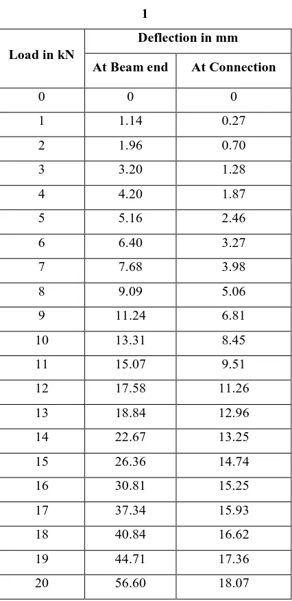
The following Table 6.1 shows the test observation of beam column specimen 1
Table 6.1 Experimental observation of specimen
1
Load in kN
Deflection in mm
At Beam end At Connection
0 0 0
1 1.14 0.27
2 1.96 0.70
3 3.20 1.28
4 4.20 1.87
5 5.16 2.46
6 6.40 3.27
7 7.68 3.98
8 9.09 5.06
9 11.24 6.81
10 13.31 8.45
11 15.07 9.51
12 17.58 11.26
13 18.84 12.96
14 22.67 13.25
15 26.36 14.74
16 30.81 15.25
17 37.34 15.93
18 40.84 16.62
19 44.71 17.36
20 56.60 18.07
The ultimate load observed by the specimen 1 is 24 kN. The maximum deflection observed for the load of 20 kN is 56.60 mm at free end and 18.07 mm at connection region.
6.3.1 Load vs Deflection graph of specimen 1
The following Fig.6.1 (a) and 6.2(b) shows the deflection curve for the specimen 1.
Fig. 6.1.1(a) Load vs Deflection graph for
specimen 1 at free end
Fig. 6.1.1 (b) Load vs Deflection graph for
specimen 1 at connection
6.4 Results of specimen 2
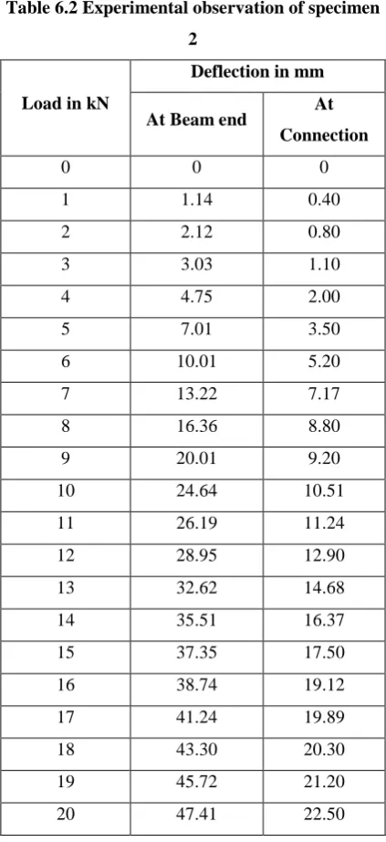
The following Table 6.2 shows the test observation of beam column specimen 2
0
5
10
15
20
25
0
50
100
L
o
a
d
in kN
Deflection in mm
Experim
ental
0
20
40
0
10
20
L
o
a
d
in kN
Deflection in mm
Experimental
ISSN 2348 – 7968
Table 6.2 Experimental observation of specimen
2
Load in kN
Deflection in mm
At Beam end At
Connection
0 0 0
1 1.14 0.40
2 2.12 0.80
3 3.03 1.10
4 4.75 2.00
5 7.01 3.50
6 10.01 5.20
7 13.22 7.17
8 16.36 8.80
9 20.01 9.20
10 24.64 10.51
11 26.19 11.24
12 28.95 12.90
13 32.62 14.68
14 35.51 16.37
15 37.35 17.50
16 38.74 19.12
17 41.24 19.89
18 43.30 20.30
19 45.72 21.20
20 47.41 22.50
The ultimate load obtained by the specimen 2 is 22 kN. The maximum deflection observed for the 20 kN load is 47.41 mm at free end and 22.50 mm at connection region.
6.4.1 load vs deflection graph of specimen 2
The following Fig.6.5 and 6.6 shows the deflection curve for the specimen 2.
Fig. 6.4.1(a) Load vs Deflection graph for
specimen 2 at beam end
Fig. 6.4.1 (b) Load vs Deflection graph for
specimen 2 at connection.
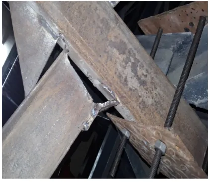
6.5 Failures in specimens
The following Figures 6.5 (a) and 6.5 (b) shows the failure on specimens.
Fig 6.5 (a)
0
5
10
15
20
25
0
50
L
o
a
d
in kN
Deflection in mm
Experime
ntal
0
20
40
0
20
40
L
o
a
d
in kN
Deflection in mm
Experimental
Fig 6.5 (b)
7. Conclusion
a. The connection was made by seat and gusset plate, due to interaction in beam column by means of weld, the connection strength was calculated as 20 kN.
b. The maximum deflection at free end s 68.83 mm by experimentally. By comparing the both experimental results at free end and the deflection is 1.26 times higher.
c. Over all it was observed that failure happened between the gusset plate and beam. There was a bending observed in the angle section too.
d. From the comparison of experimental results that the results obtained from the experimental work are 10 % more with seat angle. So the specimen is safe in the strength point of view. The capacity of connection is larger in experimental work compare with seat angle connection.
References
1) XuhongQiang et al “Behavior of beam-to-column high strength steel endplate connections under fire conditions” Engineering Structures, Volume 64, 1 April 2014, pages 39–51
2) Sriram Kalaga “Design of bolded end plate beam to column connections” Journal of Structural Engineering No. 31-18 Vol. 31, No.3, October-December 2004 pp. 181-188.
3) H.asada et al‘ Strength Evaluation on Interface Weld of Gusset Plate ‘Middle- East Journal of Scientific Research 13 (10): 1312-1318, 2013 ,ISSN 1990-9233
4) Christopher d.stoakes “beam-column connection flexural behavior of concentrically braced frames” International Journal of Engineering Research and General Science Volume 2, Issue 3, April-May 2014
5) Yuanqing Wang “Finite element analysis of beam to column end plate bolted connection” Civil Engineering & Architecture Vol. 55 No. 1 (2012)
6) Kensaku Kaneko et al “Analysis of beam-column-gusset components in 5-story value-added frame”14P
th
P