ND-70922 (E) ISSUE 1 STOCK # 151991
Open Application Interface (OAI)
System Manual
®JULY, 2000
LIABILITY DISCLAIMER
NEC America, Inc. reserves the right to change the specifications, functions, or features, at any time, without notice.
NEC America, Inc. has prepared this document for use by its employees and customers. The information contained herein is the property of NEC America, Inc. and shall not be reproduced without prior written approval from NEC America, Inc.
NEAX and Dterm are registered trademarks of NEC Corporation. Copyright 2000
NEC America, Inc.
ISSUE 1 ISSUE 2 ISSUE 3 ISSUE 4
DATE JULY, 2000 DATE DATE DATE
ISSUE 5 ISSUE 6 ISSUE 7 ISSUE 8
DATE DATE DATE DATE
NEAX2000 IVS2
Open Application Interface (OAI) System Manual Revision Sheet 1/2
ND-70922 (E) PAGE No.
ISSUE No.
1 2 3 4 5 6 7 8
i 1 ii 1 iii 1 iv 1 1 1 2 1 3 1 4 1 5 1 6 1 7 1 8 1 9 1 10 1 11 1 12 1 13 1 14 1 15 1 16 1 17 1 18 1 19 1 20 1 21 1 22 1 23 1 24 1 25 1 26 1 27 1 28 1 29 1 30 1 31 1 32 1 33 1 34 1 35 1 36 1 37 1 38 1 39 1 40 1 41 1 42 1 43 1 44 1 45 1 46 1 47 1 48 1 49 1 50 1 51 1 52 1 53 1 54 1 55 1 56 1 57 1 58 1 59 1 60 1 61 1 62 1 63 1 64 1 65 1 66 1 67 1 68 1 69 1 70 1 71 1 72 1 PAGE No. ISSUE No.
ISSUE 1 ISSUE 2 ISSUE 3 ISSUE 4
73 1
74 1
75 1
76 1
77 1
78 1
79 1
80 1
PAGE No.
ISSUE No.
1 2 3 4 5 6 7 8
PAGE No.
ISSUE No.
NEAX2000 IVS2 OAI System Manual
ND-70922 (E), Issue 1.0 Page i
NEAX2000 IVS
2OAI System Manual
TABLE OF CONTENTS
Page
LIST OF FIGURES . . . iii
LIST OF TABLES . . . iv
INTRODUCTION . . . 1
PURPOSE . . . . . 1
OUTLINE OF THIS MANUAL . . . 1
REFERENCE MANUALS . . . 2
CHAPTER 1 GENERAL INFORMATION . . . 3
SYSTEM OUTLINE . . . 4
OAI with RS-232C . . . 4
External Processor Connection . . . 4
RS RVS-15 CA-A/RS RVS-15S CA-A . . . 6
RS RVS-4 CA-A/RS RVS-4 CA-C . . . 6
RS RVS-4S CA-A/RS RVS-4S CA-C . . . 6
RS NORM-4 CA-A/RS NORM-4S CA-A . . . 7
OAI with TCP/IP-Ethernet . . . 8
SYSTEM SPECIFICATIONS . . . 9
RS-232C Interface Specification . . . 9
MODEM Specification . . . 9
CHAPTER 2 INSTALLATION . . . 11
PRECAUTIONS . . . 12
REQUIRED EQUIPMENT . . . 15
Required Equipment for OAI with RS-232C Interface . . . 15
Required Equipment for OAI with TCP/IP-Ethernet . . . 16
INSTALLATION PROCEDURE . . . 17
Installation Procedure for OAI with RS-232C . . . 17
Installation Procedure for OAI with TCP/IP-Ethernet . . . 17
Mounting PN-AP01 Card . . . 18
Mounting PN-CC01 Card . . . 19
Mounting PN-CP15 Card . . . 20
Cabling between PN-AP01 Card and External Processor . . . 21
TABLE OF CONTENTS
Page
CHAPTER 3 SYSTEM DATA PROGRAMMING . . . 25
HOW TO READ THIS CHAPTER. . . 26
AP Initialization . . . 26
Preparation before Programming . . . 26
LIST OF COMMANDS RELATED TO OAI . . . 27
AP01 INITIALIZATION . . . 33
OAI COMMUNICATION DATA ASSIGNMENT (TCP/IP) . . . 34
OAI COMMUNICATION DATA ASSIGNMENT (RS-232C) . . . 36
DATA ASSIGNMENT FOR MSF . . . 38
DATA ASSIGNMENT FOR TMF . . . 43
DATA ASSIGNMENT FOR SCF. . . 45
DATA ASSIGNMENT FOR FLF . . . 51
DATA ASSIGNMENT FOR KTF . . . 53
DATA ASSIGNMENT FOR ACF. . . 54
DATA ASSIGNMENT FOR SSF . . . 56
DATA ASSIGNMENT FOR SMF . . . 57
CHAPTER 4 TROUBLESHOOTING . . . 59
TROUBLESHOOTING FOR OAI WITH RS-232C . . . 60
TROUBLESHOOTING FOR OAI WITH TCP/IP-ETHERNET . . . 62
Troubleshooting Information for ETHER Card . . . 62
Troubleshooting Information for PN-AP01 Card . . . 63
Replacement Procedure for PN-AP01/PN-CC01 Card . . . 64
CHAPTER 5 CIRCUIT CARD INFORMATION . . . 65
HOW TO READ THIS CHAPTER. . . 66
MOUNTING LOCATION OF CIRCUIT CARD . . . 67
LIST OF REQUIRED CIRCUIT CARD . . . 68
PN-CP15 (FP) . . . 69
PN-AP01 (AP01) . . . 71
PN-CC01 (ETHER) . . . 74
LIST OF FIGURES
Figure Title Page
NEAX2000 IVS2 OAI System Manual
ND-70922 (E), Issue 1.0 Page iii
Figure 1-1 System Outline of OAI with RS-232C . . . 4
Figure 1-2 External Processor Connection for RS-232C Interface . . . 5
Figure 1-3 System Outline of OAI with TCP/IP-Ethernet . . . 8
Figure 2-1 Static Electricity Guard (1 of 2) . . . 12
Figure 2-1 Static Electricity Guard (2 of 2) . . . . 13
Figure 2-2 Installation Procedure for OAI with RS-232C Interface . . . 17
Figure 2-3 Installation Procedure for OAI with TCP/IP-Ethernet . . . 17
Figure 2-4 Cable Running of RS RVS Cable/RS NORM Cable . . . 21
Figure 2-5 Direct Connection . . . 22
Figure 2-6 MODEM Connection . . . 22
Figure 2-7 Cable Connections on PN-CC01 Card . . . 23
Figure 2-8 Cabling 48-TW-0.3 CONN CA and 10 BASE-T Twisted Pair Cable . . . 24
LIST OF TABLES
Table Title Page
Table 1-1 RS-232C Interface Specification . . . 9
Table 1-2 MODEM Specification . . . 9
Table 2-1 Required Equipment for OAI with RS-232C Interface . . . 15
Table 2-2 Required Equipment for OAI with TCP/IP-Ethernet . . . 16
Table 3-1 List of Commands Related to OAI . . . 27
Table 3-2 IP Address Assignment Patterns (PN-CC01 Card) . . . 35
Table 4-1 Troubleshooting Information for OAI with RS-232C . . . 60
Table 4-2 Troubleshooting Information for ETHER Card . . . 62
Table 4-3 Troubleshooting Information for PN-AP01 Card . . . 63
INTRODUCTION
Purpose
NEAX2000 IVS2 OAI System Manual
ND-70922 (E), Issue 1.0 Page 1
INTRODUCTION
PURPOSE
This manual explains the system description, installation procedure, programming procedure and troubleshooting information for providing the Open Application Interface (OAI) to the
NEAX2000 IVS2.
OUTLINE OF THIS MANUAL
This manual contains the following chapters and appendix:
CHAPTER 1 GENERAL INFORMATION
This chapter explains the system outline and specifications of the OAI system.
CHAPTER 2 INSTALLATION
This chapter explains the hardware installation procedure to provide an OAI interface to the PBX.
CHAPTER 3 SYSTEM DATA PROGRAMMING
This chapter explains the programming procedure to provide the OAI feature to the PBX.
CHAPTER 4 TROUBLESHOOTING
This chapter explains troubleshooting information after installing the OAI system.
CHAPTER 5 CIRCUIT CARD INFORMATION
This chapter explains the mounting location, the meaning of lamp indications, and the method of switch settings of each circuit card for OAI.
INTRODUCTION
Reference Manuals
REFERENCE MANUALS
Refer to the following manuals during installation:
Installation Procedure Manual: Describes the installation procedure of the PBX system.
Command Manual: Describes Customer Administration Terminal (CAT)
operation, command function and setting data required for programming the system, and Resident System Program.
Office Data Programming Manual: Contains the Customer Specification Sheet and Office
NEAX2000 IVS2 OAI System Manual
ND-70922 (E), Issue 1.0 Page 3
CHAPTER 1
GENERAL INFORMATION
CHAPTER 1 GENERAL INFORMATION
System Outline
SYSTEM OUTLINE
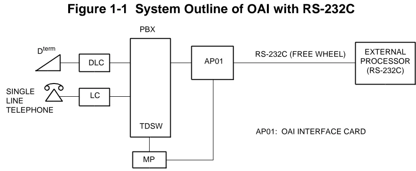
The PBX is equipped with an interface to provide user applications through an external processor. The interface supports RS-232C (Free Wheel) protocol and TCP/IP protocol.
OAI with RS-232C
For adding the interface with RS-232C, the AP01 card (OAI Interface Card) is required. Figure 1-1 shows the system outline of OAI with RS-232C.
Figure 1-1 System Outline of OAI with RS-232C
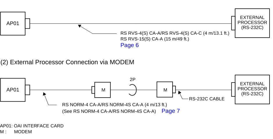
External Processor Connection
The PBX can be directly connected to an external processor with a cable. The maximum length of the cable is 15 m (49 ft.). The PBX also can be connected to a MODEM for extending the distance between the PBX and the external processor. The maximum length of the cable from PBX to modem is 4 m (13 ft.). Figure 1-2 shows the external processor connection for RS-232C interface.
AP01: OAI INTERFACE CARD RS-232C (FREE WHEEL) PBX
MP DLC
LC
AP01
EXTERNAL PROCESSOR
(RS-232C) SINGLE
LINE TELEPHONE
Dterm
CHAPTER 1 GENERAL INFORMATION
System Outline
NEAX2000 IVS2 OAI System Manual
ND-70922 (E), Issue 1.0 Page 5
Figure 1-2 External Processor Connection for RS-232C Interface
AP01 M M
2P
RS-232C CABLE
EXTERNAL PROCESSOR
(RS-232C)
AP01
EXTERNAL PROCESSOR
(RS-232C)
(1) External Processor Direct Connection
AP01: OAI INTERFACE CARD M : MODEM
(2) External Processor Connection via MODEM
RS RVS-4(S) CA-A/RS RVS-4(S) CA-C (4 m/13.1 ft.) RS RVS-15(S) CA-A (15 m/49 ft.)
Page 6
CHAPTER 1 GENERAL INFORMATION
System Outline
RS RVS-15 CA-A/RS RVS-15S CA-A RS RVS-4 CA-A/RS RVS-4 CA-C RS RVS-4S CA-A/RS RVS-4S CA-C
NOTE: If the external processor does not send DTR or RTS signal, cut the signal lead marked
by X in the D-Sub connector (external processor side) as shown in the wiring diagram below.
See APPENDIXDEFINITION OF V.24 SIGNAL LEADS. Page 79
05A-TXD 05B-GND 06A-TXC (2) 06A-TXC (2) 06B-RXC 06D-TXC (1) 04B-RXD 04A-RTS 03-RXD 01-GND 06-DSR 24-TXC (1) 17-RXC 02-TXD 08-DCD 15-TXC (2) 02B-GND 03A-DSR 03B-CTS 02A-DCD 01C-LALB 07-GND 20-DTR 05-CTS 04-RTS 18-LALB
D C B A
06 TXC (1) RXC TXC (2)
05 DTR GND TXD
04 (RT) RXD RTS
13 ----12 ----11 ----10 ----09 ----08 DCD 07 GND 06 DSR 25 ----24 TXC (1) 23 ----22 ----21 ----20 DTR 19 ----X NOTE X X X
RS RVS-15 CA-A/RS RVS-15S CA-A: 15 m (49.2 ft.) MAX.
X RS RVS-4 CA-A/RS RVS-4 CA-C/
CHAPTER 1 GENERAL INFORMATION
System Outline
NEAX2000 IVS2 OAI System Manual
ND-70922 (E), Issue 1.0 Page 7
See APPENDIXDEFINITION OF V.24 SIGNAL LEADS. Page 79
RS NORM-4 CA-A/RS NORM-4S CA-A
05A-TXD 05B-GND 05C-DTR 06A-TXC (2) 06B-RXC 06D-TXC (1) 04B-RXD 04A-RTS 02-RXD 01-GND 20-DSR 15-TXC (1) 17-RXC 03-TXD 04-DCD 24-TXC (2) 02B-GND 03A-DSR 03B-CTS 02A-DCD 01C-LALB 07-GND 06-DTR 05-CTS 08-RTS 18-LALB G: GROUND (4 m/13 ft.)
D C B A
06 TXC (1) RXC TXC (2)
05 DTR GND TXD
04 (RT) RXD RTS
03 (ST) CTS DSR
02 ---- GND DCD
01 LALB G
CHAPTER 1 GENERAL INFORMATION
System Outline
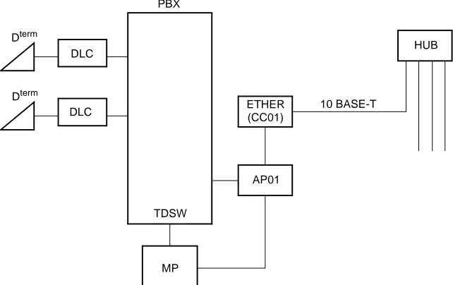
OAI with TCP/IP-Ethernet
The PBX is equipped with an interface to transmit/receive the control signals between the PBX and the Ethernet. The interface supports TCP/IP protocol. For adding the interface with TCP/IP, the ETHER card (CC01) (Ethernet Gateway Controller) is required in addition to the AP01 card.
Figure 1-3 shows the system outline of OAI with TCP/IP-Ethernet.
Figure 1-3 System Outline of OAI with TCP/IP-Ethernet
AP01: OAI INTERFACE CARD
ETHER: ETHERNET CONTROLLER (CC01)
ETHER
AP01
MP PBX
TDSW DLC
DLC Dterm
Dterm
(CC01)
HUB
CHAPTER 1 GENERAL INFORMATION
System Specifications
NEAX2000 IVS2 OAI System Manual
ND-70922 (E), Issue 1.0 Page 9
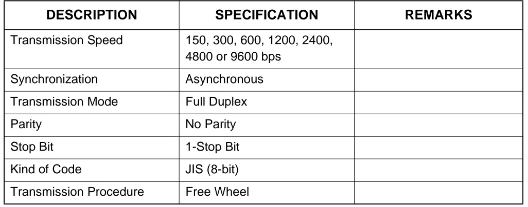
SYSTEM SPECIFICATIONS
RS-232C Interface Specification
MODEM Specification
Table 1-1 RS-232C Interface Specification
DESCRIPTION SPECIFICATION REMARKS
Transmission Speed 150, 300, 600, 1200, 2400,
4800 or 9600 bps
Synchronization Asynchronous
Transmission Mode Full Duplex
Parity No Parity
Stop Bit 1-Stop Bit
Kind of Code JIS (8-bit)
Transmission Procedure Free Wheel
Table 1-2 MODEM Specification
DESCRIPTION SPECIFICATION REMARKS
Synchronization Asynchronous
Data Speed 150, 300, 600, 1200, 2400,
4800 or 9600 bps
Transmission Mode Full Duplex
Line 4 wire
Connecting Type Ring (Dial up)/Leased
CHAPTER 2
INSTALLATION
NEAX2000 IVS2 OAI System Manual
Page 12 ND-70922 (E), Issue 1.0
CHAPTER 2 INSTALLATION
Precautions
PRECAUTIONS
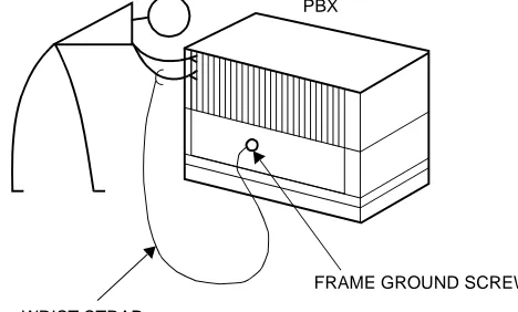
Static Electricity Guard
You must wear a grounded wrist strap to protect circuit cards from static electricity.
Figure 2-1 Static Electricity Guard (1 of 2)
• WHEN PLUGGING/UNPLUGGING A CIRCUIT CARD
• WHEN HOLDING A CIRCUIT CARD
PBX
WRIST STRAP
FRAME GROUND SCREW
CARD FRONT
CHAPTER 2 INSTALLATION
Precautions
Figure 2-1 Static Electricity Guard (2 of 2)
• WHEN MAKING A SWITCH SETTING ON A CIRCUIT CARD
• WHEN CARRYING A CIRCUIT CARD
The mark shown below is attached to the sheet for work in which circuit cards are handled. When engaging in such work, the installer must be careful not to cause damage by static electricity.
WEAR A WRIST STRAP AND PERFORM THE WORK ON A GROUNDED
CONDUCTIVE WORK SURFACE. CIRCUIT
CARD
WHEN CARRYING A CIRCUIT CARD AROUND, KEEP THE CARD IN A CONDUCTIVE POLYETHYLENE BAG. CIRCUIT
CARD
CONDUCTIVE POLYETHYLENE BAG
ATTENTION
Contents Static Sensitive: Handling
NEAX2000 IVS2 OAI System Manual
Page 14 ND-70922 (E), Issue 1.0
CHAPTER 2 INSTALLATION
Precautions
Caution
You must hold the edge of a circuit card when plugging or unplugging the circuit card. If you touch another area, you may be exposed to hazardous voltages.
CARD FRONT
NEVER TOUCH THE
CHAPTER 2 INSTALLATION
Required Equipment
REQUIRED EQUIPMENT
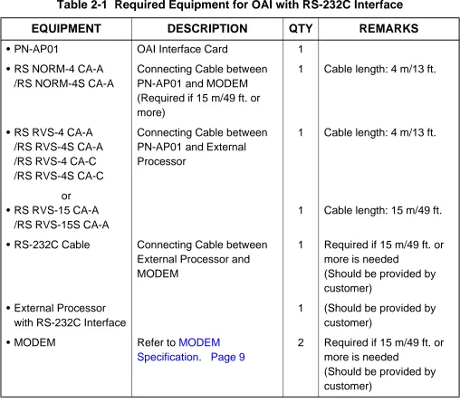
Table 2-1 and Table 2-2 show the required equipment when the OAI is provided through an external processor with RS-232C interface, or through the Ethernet with TCP/IP.
Required Equipment for OAI with RS-232C Interface
Table 2-1 Required Equipment for OAI with RS-232C Interface
EQUIPMENT DESCRIPTION QTY REMARKS
• PN-AP01 OAI Interface Card 1
• RS NORM-4 CA-A /RS NORM-4S CA-A
Connecting Cable between PN-AP01 and MODEM (Required if 15 m/49 ft. or more)
1 Cable length: 4 m/13 ft.
• RS RVS-4 CA-A /RS RVS-4S CA-A /RS RVS-4 CA-C /RS RVS-4S CA-C
Connecting Cable between PN-AP01 and External Processor
1 Cable length: 4 m/13 ft.
or • RS RVS-15 CA-A
/RS RVS-15S CA-A
1 Cable length: 15 m/49 ft.
• RS-232C Cable Connecting Cable between
External Processor and MODEM
1 Required if 15 m/49 ft. or more is needed
(Should be provided by customer)
• External Processor with RS-232C Interface
1 (Should be provided by
customer)
• MODEM Refer to MODEM
Specification. Page 9
2 Required if 15 m/49 ft. or more is needed
NEAX2000 IVS2 OAI System Manual
Page 16 ND-70922 (E), Issue 1.0
CHAPTER 2 INSTALLATION
Required Equipment
Required Equipment for OAI with TCP/IP-Ethernet
Table 2-2 Required Equipment for OAI with TCP/IP-Ethernet
EQUIPMENT DESCRIPTION QTY REMARKS
• PN-AP01 OAI Interface Card 1
• PN-CC01 Ethernet Control Card 1
• 48-TW-0.3 CONN CA BUS Cable between
PN-AP01 and PN-CC01
1 Cable length:
0.3 m/1 ft.
• 10 BASE-T twisted pair cable (TIA/EIA category 3 or larger)
10 BASE-T Cable between PN-CC01 and Ethernet
1 Cable length:
Max. 100 m/328 ft. (Should be provided by customer)
CHAPTER 2 INSTALLATION
Installation Procedure
INSTALLATION PROCEDURE
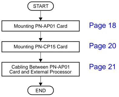
Installation Procedure for OAI with RS-232C
Install the OAI system with RS-232C interface according to the following procedure.
Figure 2-2 Installation Procedure for OAI with RS-232C Interface
Installation Procedure for OAI with TCP/IP-Ethernet
Install the OAI system with TCP/IP-Ethernet according to the following procedure.
Figure 2-3 Installation Procedure for OAI with TCP/IP-Ethernet Mounting PN-CP15 Card
Mounting PN-AP01 Card
Cabling Between PN-AP01 Card and External Processor
END START
Page 18 Page 20 Page 21
END START
Cabling BUS Cable and 10 BASE-T Cable Mounting PN-CC01 Card
Mounting PN-AP01 Card
Mounting PN-CP15 Card
NEAX2000 IVS2 OAI System Manual
Page 18 ND-70922 (E), Issue 1.0
CHAPTER 2 INSTALLATION
Installation Procedure
Mounting PN-AP01 Card
(1) Confirm the correct switch settings. See CHAPTER 5. Page 65
Before mounting the card, set the MB switch to UP position.
(2) Mount the PN-AP01 card in one of the following AP slots.
PIM 0 : AP00-AP10 slot PIM 1-7: AP00-AP11 slot
After mounting the card, set the MB switch to DOWN position.
Contents Static Sensitive: Precautions Required Handling
CHAPTER 2 INSTALLATION
Installation Procedure
Mounting PN-CC01 Card
(1) Confirm the correct switch settings. See CHAPTER 5. Page 65
(2) Mount the PN-CC01 card in one of the following AP slots.
PIM 0 : AP00-AP10 slot PIM 1-7: AP00-AP11 slot
Contents Static Sensitive: Precautions Required Handling
NEAX2000 IVS2 OAI System Manual
Page 20 ND-70922 (E), Issue 1.0
CHAPTER 2 INSTALLATION
Installation Procedure
Mounting PN-CP15 Card
(1) Confirm the correct switch settings. See CHAPTER 5. Page 65
Before mounting the card, set the MB switch to UP position.
(2) Mount one PN-CP15 card in the each FP slot of PIM0, PIM2, PIM4 and PIM6, according to the system configuration.
After mounting the card, set the MB switch to DOWN position.
Contents Static Sensitive: Precautions Required Handling
CHAPTER 2 INSTALLATION
Installation Procedure
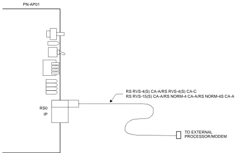
Cabling between PN-AP01 Card and External Processor
(1) Connect the RS RVS cable or RS NORM cable onto the “RS0” connector on the PN-AP01 card, as shown in Figure 2-4.
Figure 2-4 Cable Running of RS RVS Cable/RS NORM Cable
PN-AP01
RS RVS-4(S) CA-A/RS RVS-4(S) CA-C
TO EXTERNAL IP
NEAX2000 IVS2 OAI System Manual
Page 22 ND-70922 (E), Issue 1.0
CHAPTER 2 INSTALLATION
Installation Procedure
(2) Connect the RS RVS cable or RS NORM cable, as shown in Figure 2-5 and Figure 2-6. When connecting an External Processor directly:
Connect the External Processor to the PN-AP01 using an RS RVS-4(S) CA-A/RS RVS-4(S) CA-C/RS RVS-15(S) CA-A cable, as shown in Figure 2-5.
Figure 2-5 Direct Connection
When connecting an External Processor using MODEMs:
Connect the External Processor through the MODEMs, as shown in Figure 2-6. In this case, the RS NORM-4 CA-A/RS NORM-4S CA-A should be used for DCE-DCE connection. When the cable length between the External Processor and PBX is more than 15 m/49 ft., MODEMs are required.
Figure 2-6 MODEM Connection PBX
(PIM0-PIM7)
PN-AP01
RS0 RS RVS-4(S) CA-A/RS RVS-4(S) CA-C (4 m/13.1 ft.) External Processor (RS-232C) RS RVS-15(S) CA-A (15 m/49 ft.)
External Processor (RS-232C) MODEM
MODEM
RS NORM-4 CA-A/RS NORM-4S CA-A (4 m /13 ft.)
PN-AP01
RS0 PBX
(PIM0-PIM7)
CHAPTER 2 INSTALLATION
Installation Procedure
Cabling BUS Cable and 10 BASE-T Cable
(1) Connect the 48-TW-0.3 CONN CA (BUS cable) onto the “IP” connector on the PN-CC01 card, as shown in Figure 2-7.
(2) Connect the 10 BASE-T twisted pair cable (TIA/EIA Category 3 or larger) onto the “10 BASE-T” connector on the PN-CC01 card, as shown in Figure 2-7.
Figure 2-7 Cable Connections on PN-CC01 Card
TO PN-AP01
48-TW-0.3 CONN CA IP
PN-CC01
10 BASE-T TO 10 BASE-T HUB
NEAX2000 IVS2 OAI System Manual
Page 24 ND-70922 (E), Issue 1.0
CHAPTER 2 INSTALLATION
Installation Procedure
(3) Connect the 48-TW-0.3 CONN CA onto the “IP” connector on the PN-AP01 card, as shown in Figure 2-8.
(4) Connect the 10 T twisted pair cable (TIA/EIA category 3 or larger) onto the 10 BASE-T HUB on the Ethernet.
Figure 2-8 Cabling 48-TW-0.3 CONN CA and 10 BASE-T Twisted Pair Cable
PN-CC01
PN-AP01
48-TW-0.3 CONN CA (0.3 m/1 ft.)
10 BASE-T TWISTED PAIR CABLE (TIA/EIA CATEGORY 3 OR LARGER)
RS0 IP IP
CHAPTER 3
SYSTEM DATA
PROGRAMMING
NEAX2000 IVS2 OAI System Manual
Page 26 ND-70922 (E), Issue 1.0
CHAPTER 3 SYSTEM DATA PROGRAMMING
How to Read This Chapter
HOW TO READ THIS CHAPTER
AP Initialization
When first programming the OAI system data, initialize the PN-AP01 card using the procedure described in AP01 Initialization.
Preparation before Programming
Before programming, confirm that the system is under the following conditions.
• The system is under On-Line mode. (“RUN” lamp is flashing on the MP card.)
• MB (Make Busy) switch of AP01 card is set to “DOWN” (In Service) position.
• All the system data pertaining to the stations, trunks and service features are already programmed.
NOTE: The tenant service assignment for the stations in the PBX must match the tenant service
assignment for those same stations in the User Application Processor (UAP). If these assignments do not match, the OAI features will not work.
According to the programming procedures described in this chapter, assign the system data related to the OAI. For details of each command, refer to the Command Manual.
In the programming procedure, the meaning of (1), (2) and the markings are as follows.
(1) : 1st Data
(2) : 2nd Data
: Initial Data
With the system data clear command (CM00, CM01), the data with this marking is automatically assigned for each command.
: System Initialization
After entering the data, a system reset (press SW1 on the MP card) is required.
: AP Initialization
After entering the data, an AP reset (UP and DOWN of MB switch on the AP01 card) is required.
INITIAL
CHAPTER 3 SYSTEM DATA PROGRAMMING
List of Commands Related to OAI
LIST OF COMMANDS RELATED TO OAI
Table 3-1 shows the commands related to the OAI with each facility (MSF, TMF etc.).
Table 3-1 List of Commands Related to OAI
ITEM
RELATED COMMAND
COMMAND
No. 1ST DATA 2ND DATA MEANING
AP01 Initial-ization Data
CM05 Y=0 04-15 07 AP Number of PN-AP01
CMD6 Y=0 0000 CCC PN-AP01 Memory All Clear
OAI Com- muni-cation Data (TCP/ IP)
CMD7 Y=9 00-03 0-255 IP Address of TCP/IP-Ethernet
OAI Com- muni-cation Data (RS-232C)
CMA6 YY=04 3 0-6 AP Port Data
CMA6 YY=05 3 1
CMA6 YY=06 3 7
CMA6 YY=07 3 1
CMA6 YY=08 3 1
CMA6 YY=09 3 06
CMA6 YY=10 3 0/1
CMA6 YY=11 3 0/1
CMA6 YY=12 3 0/1
NEAX2000 IVS2 OAI System Manual
Page 28 ND-70922 (E), Issue 1.0
CHAPTER 3 SYSTEM DATA PROGRAMMING
List of Commands Related to OAI
MSF
CM10 000-763
EB000-EB127
Digital Announcement Trunk Card No.
CM12 YY=02 Station No. 00-15 Service Restriction Class
CM15 YY=59 00-15 1
CM20 Y=0-3 Access Code A084 MSF Access Code
CM20 Y=0-3 Access Code A100-A102 Digital Announcement Trunk
Access Code
CM41 Y=0 56 00-99 Message Replay Timer/Tone
Sending Timer
CM49 YY=00 000-127 10 Announcement Service for OAI
CM90 YY=00 My Line No.
+ + Key
No.
F1032-F1047 OAI Function Key
CMD7 Y=0
F1032-F1047
128-191 MSF Operation Code
CMD7 Y=0
F1032-F1047
DCX (X=1-3) Digit Number of Digit Code
CMD7 Y=1 Access Code 128-191 MSF Operation Code
CMD7 Y=2 000-127 1000-1127 Digital Announcement Trunk Card
No.
CMD7 Y=3 00 000-127 RR Timer
CMD7 Y=4 00 00-32 Maximum number of terminals to
be in MSF simultaneously
CMD7 Y=6 Digit Code 128-191 Operation Code for MSF
CMD7 Y=7
F1032-F1047
00/01 Chime from Dterm when Receiving
RR Signal
TMF
CM90 YY=00 My Line No.
+ + Key
No.
F1032-F1047 OAI Function Key
Table 3-1 List of Commands Related to OAI (Continued)
ITEM
RELATED COMMAND
COMMAND
No. 1ST DATA 2ND DATA MEANING
,
CHAPTER 3 SYSTEM DATA PROGRAMMING
List of Commands Related to OAI
TMF
CMD7 Y=0
F1032-F1047
192-255 TMF Operation Code
CMD7 Y=0
F1032-F1047
DCX (X=1-3) Digit Number of Digit Code
CMD7 Y=3 00 000-127 RR Timer
CMD7 Y=4 01 00-32 Maximum number of terminals to
be in TMF simultaneously
CMD7 Y=6 Digit Code 192-255 Operation Code for TMF
CMD7 Y=7
F1032-F1047
00/01 Chime from Dterm when Receiving
RR Signal
CMD7 Y=8 00-03 00/01 Chime from Dterm, Display
Guidance when setting up TMF
SCF
CM08 465 0/1 Facility Error detail information
from PBX to computer
CM10 000-763
EB002-EB127
Digital Announcement Trunk Card No.
CM11 000-255 Virtual-Line
number
Virtual Line number
(Assign only one per system)
CM17 Y=0 Station No. Another
Station No.
UCD Group
CM17 Y=1 Station No. 2/3 Member station/Pilot station
CM17 Y=2 Station No. 00-15 UCD Group No.
CM17 Y=A Station No. 0/1 Method of Sending
Multi-Connection Announcement
Table 3-1 List of Commands Related to OAI (Continued)
ITEM
RELATED COMMAND
COMMAND
NEAX2000 IVS2 OAI System Manual
Page 30 ND-70922 (E), Issue 1.0
CHAPTER 3 SYSTEM DATA PROGRAMMING
List of Commands Related to OAI
SCF
CM42 10 01-06 Account Code Max. digit
(SCF FID=1, 3, 4, 7)
CM49 YY=00 000-127 10/1602-1663 Announcement Service for OAI/
Message Group No. for Multi-Connection Announcement Service for OAI
CMD7 Y=2 000-127 1000-1127 Digital Announcement Trunk Card
No.
FLF
CM08 216 1 AP (PN-AP01)
CM08 217 1 AP (PN-AP01)
CM15 YY=31 00-15 0/1 Authorization Code/Forced
Account Code
CM20 Y=0-3 Access Code A157 First Digit of Authorization Code
CM42 11 01-10 Max. Number of Digit for
Authorization Code
CMD7 Y=5 00 X-XXXX Office Number
CMD7 Y=A 00 0/1 Recognition of AP database
CMD7 Y=A 01 0/1 Omission of AP database
KTF
CM90 YY=00 My Line No.
+ + Key
No.
F1032-F1047 OAI Function Key
ACF
CM08 217 0/1 Processor for Checking ID Cords
CM08 362 0/1 SST after Dialing the Access Code
for ID Code Class Change
CM20 Y=0-3 Access Code A086/A087 Access Code for ID Code Class
Change
CM42 11-13 01-10 Number of digits for Authorization
Code/Forced Account Code/DISA
Table 3-1 List of Commands Related to OAI (Continued)
ITEM
RELATED COMMAND
COMMAND
No. 1ST DATA 2ND DATA MEANING
CHAPTER 3 SYSTEM DATA PROGRAMMING
List of Commands Related to OAI
ACF
CMD5 Y=3 ID code ABBCCDDEE Temporary Class Data
CMD7 Y=3 00 000-127 RR Timer
CMD7 Y=5 00 XXXX Office Number
CMD7 Y=B 00 0-3 Number of Digits for ID Codes
when AP Stops
TCF None
NTF None
ADF None
SSF (MW)
CM08 140 0/1 Message Wait Indication (MW)
CM08 235 0 Message Waiting/Message
Reminder reset
CM08 376 0/1 VMS via CCIS
CM08 443 0 VMS with MCI
CM08 444 0/1 Message Waiting lamp control
CM13 YY=03 Station No. 0 Message Waiting/Message
Reminder
Table 3-1 List of Commands Related to OAI (Continued)
ITEM
RELATED COMMAND
COMMAND
NEAX2000 IVS2 OAI System Manual
Page 32 ND-70922 (E), Issue 1.0
CHAPTER 3 SYSTEM DATA PROGRAMMING
List of Commands Related to OAI
SMF
CM08 429 0/1 Dterm subline
CM08 460 0/1 SMFN STS (Status)
CM08 461 0/1 SMFN when answering a held call
CM08 462 0/1 ANI/Caller ID/CPN to OAI
Terminal
CM08 464 0/1 TSAPI/SCF facility
CMD7 Y=A 02 0/1 SMFN/SSFN Delay Timer
MRF None
Health check
None
Table 3-1 List of Commands Related to OAI (Continued)
ITEM
RELATED COMMAND
COMMAND
CHAPTER 3 SYSTEM DATA PROGRAMMING
AP01 Initialization
AP01 INITIALIZATION
DESCRIPTION DATA
Assign an AP number to the AP01 card.
NOTE: The AP number must match the SENSE switch settings on the AP01 card.
• (1) (2)
Y=0
AP Number (04-15) 07: AP01 card
Load the initial data into the AP01 card. •
(1) (2)
Y=0 0000 CCC CMD6
START
END CM05
NEAX2000 IVS2 OAI System Manual
Page 34 ND-70922 (E), Issue 1.0
CHAPTER 3 SYSTEM DATA PROGRAMMING
OAI Communication Data Assignment (TCP/IP)
OAI COMMUNICATION DATA ASSIGNMENT (TCP/IP)
NOTE 1: The IP Address must be assigned to the 1st data 00-03 as follows.
IP Address: AAA.BBB.CCC.DDD [AAA-DDD: 2nd Data (2)]
NOTE 2: When setting the 2nd Data as shown in Table 3-2 IP Address Assignment Patterns (PN-CC01 Card) (See Page 35), note that the setting data is different from the data actually assigned.
IP Address: AAA.BBB.CCC.DDD
DESCRIPTION DATA
Assign the IP Address of TCP/IP-Ethernet.
NOTE 1, NOTE 2
• (1) (2)
Y=9
00-03: Division No. of IP Address 0-255: Address Data (1-3 digits)
1st Data (1) 00: AAA
01: BBB 02: CCC 03: DDD
START
CMD7
END
CHAPTER 3 SYSTEM DATA PROGRAMMING
OAI Communication Data Assignment (TCP/IP)
Table 3-2 IP Address Assignment Patterns (PN-CC01 Card)
PATTERN
INPUT DATA (2ND DATA)
ASSIGNED DATA
AAA BBB CCC DDD
When no data or all 0 is input
No data No data No data No data
4C.A4.XX.XX (HEX) 4C.A4: Fixed
XX.XX: According to the switch setting of SW1 (D15-D8) and SW2 (D7-D0)
(The IP Address is the same as lower 32 bits of MAC Address.)
0 0 0 0
When the data only for
Address AAA is input
0≤AAA
≤127 0 0 0
A.A4.XX.XX (HEX) A.A4: Fixed
XX.XX: According to the switch setting of SW1 (D15-D8) and SW2 (D7-D0)
(The lower 24 bits of IP Address is the same as the lower 24 bits of MAC Address.)
When the data only for
Address AAA and BBB is
input 128≤AA
A
≤191
0≤BBB
≤255 0
A.B.XX.XX (HEX) A.B: Fixed
NEAX2000 IVS2 OAI System Manual
Page 36 ND-70922 (E), Issue 1.0
CHAPTER 3 SYSTEM DATA PROGRAMMING
OAI Communication Data Assignment (RS-232C)
OAI COMMUNICATION DATA ASSIGNMENT (RS-232C)
DESCRIPTION DATA
Assign the attribute data for RS-232C port of the PN-AP01.
•
(1) (2)
YY=04 Data Transmission Speed of RS-232C port
3
0: 150 bps 1: 300 bps 2: 600 bps 3: 1200 bps 4: 2400 bps 5: 4800 bps 6: 9600 bps
• (1) (2)
YY=05 Parity Check 3
1 : Ineffective
• (1) (2)
YY=06 Synchronous/Asynchronous 3
7 : Asynchronous
• (1) (2)
YY=07 Duplex/Half-duplex 3
1 : Duplex
START
CMA6
A
CHAPTER 3 SYSTEM DATA PROGRAMMING
OAI Communication Data Assignment (RS-232C)
DESCRIPTION DATA
• (1) (2)
YY=08 Stop Bit 3
1 : 1-Stop Bit
• (1) (2)
YY=09 Type of Code 3
06: JIS (8-bit)
• (1) (2)
YY=10 Flow Control by DCD Signal 3
0 : Ineffective
1 : Effective
• (1) (2)
YY=11 RTS Signal Control 3
0 : Ineffective (RTS Signal ON)
1 : Effective
NOTE: When connecting an external processor with RS-232C in-terface via MODEM, assign 0 (RTS Signal ON) as the 2nd data.
•
(1) (2)
YY=12 Designation of Signal for Detecting Line Disconnection 3
0 : DCD (with MODEM)
1 : DSR (without MODEM)
• (1) (2)
YY=20 Designation of Facility 3 2: OAI • (1) (2) YY=21 Priority 3
0: 1st Priority
• (1)
YY=24 Kind of Procedure 3
CMA6 A
NEAX2000 IVS2 OAI System Manual
Page 38 ND-70922 (E), Issue 1.0
CHAPTER 3 SYSTEM DATA PROGRAMMING
Data Assignment for MSF
DATA ASSIGNMENT FOR MSF
To start up MSF from Dterm by using an OAI function key:
DESCRIPTION DATA
Assign the OAI function key for starting up
MSF to a Dterm.
• (1) (2)
YY=00
My Line No. + + Key No.
F1032-F1047: OAI Function Key No. 0-15
When pressing the OAI function key to start up MSF, assign the operation code to the OAI function key assigned by CM90.
• (1)
(2) Y=0
F1032-F1047: OAI Function Key No. 0-15
128-191: Operation Code for MSF
When dialing a digit code (1-3 digits) after pressing OAI function key to start up MSF, assign the digit number of digit code, then assign the operation code to the digit code.
• (1)
(2) Y=0
F1032-F1047: OAI Function Key No. 0-15
DCX (X=1-3) : Digit Number of Digit Code
• (1) (2)
Y=6
X-XXX: Digit Code (X=0-9, #) 128-191: Operation Code for MSF
Assign the waiting timer for receiving an answer signal (RR signal) after starting up MSF, if required.
• (1) (2)
Y=3 00
000-127: 8-508 sec.
(4-sec. increments)
If no data is set, the default setting is 8 sec.
Specify a chime from Dterm when
receiving RR signal of MSF.
• (1)
(2) Y=7
F1032-F1047: OAI Function Key No. 0-15
00 : Not sent
01 : To send
CMD7 START
CM90
END
CHAPTER 3 SYSTEM DATA PROGRAMMING
Data Assignment for MSF
To start up MSF from PB Telephone/Dterm by using an access code:
DESCRIPTION DATA
Assign the Service Restriction Class for starting up MSF to the required stations.
NOTE: After starting up the MSF from a
PB telephone or Dterm, the PB
re-ceiver is busy during MSF mode. Therefore, you must make sure that a call origination is not avail-able if all PB receivers are used. To prevent the “all busy,” we rec-ommend using the OAI function
key on Dterm, as the PB receiver
is not used for the Dterm.
• (1) (2)
YY=02
X-XXXX: Station No. XX ZZ
ZZ: 00-15 : Service Restriction Class
B
• (1)
(2)
YY=59
00-15: Service Restriction Class B assigned by CM12 Y=02
1 : Allow
Assign the access code for starting up MSF.
• (1) (2)
Y=0-3 Number Plan Group 0-3 X-XXXX: Access Code for MSF A084
Assign the operation code to the access code assigned by CM20>A084.
NOTE 1: The operation code means a number to designate each OAI application.
NOTE 2: The maximum number of operation code is 16.
• (1)
(2) Y=1
X-XXXX: Access Code assigned by CM20>A084
128-191: Operation Code for MSF
Assign the waiting timer for receiving an answer signal after starting up MSF, if required. • (1) (2) Y=3 00
000-127: 8-508 sec. (4-sec. increments)
If no data is set, the default setting is 000 (8-sec.).
Assign the number of the terminal (PB telephone) to be in the terminal mode
NEAX2000 IVS2 OAI System Manual
Page 40 ND-70922 (E), Issue 1.0
CHAPTER 3 SYSTEM DATA PROGRAMMING
Data Assignment for MSF
DESCRIPTION DATA
When sending a message through the Digital Announcement Trunk (PN-2DATA)
to PB telephone/Dterm user by using
TCF-D facility:
When sending a tone to PB telephone/
Dterm user by using TCF-D facility:
When not sending a message or tone: A
CMD7
C B
CHAPTER 3 SYSTEM DATA PROGRAMMING
Data Assignment for MSF
DESCRIPTION DATA
Assign a Digital Announcement Trunk card number to the required LEN.
NOTE 1: The Digital Announcement Trunk card number must be assigned to the first LEN (Level 0), the third LEN (Level 2), the fifth LEN (Level 4) and the seven LEN (Level 6) of each LT slot.
NOTE 2: EB000 and EB001 are dedicated to built-in Digital Announcement Trunk of the MP card.
(1) (2)
LEN: 000-763
EB002-EB127: Digital Announcement Trunk Card No. For PIM0/1: EB002-EB031 For PIM2/3: EB032-EB063 For PIM4/5: EB064-EB095
For PIM6/7: EB096-EB127NOTE 2
Assign the function of the Digital Announcement Trunk card.
• (1)
(2)
YY=00
000-001: Built-in DAT on MP card 002-127: Digital Announcement Trunk
Card No. assigned by CM10 (EB002-EB127)
10: Announcement Service in the OAI Terminal mode
To record, replay or delete a message, assign the respective Digital
Announcement Trunk access code.
• (1) (2)
Y=0-3 Numbering Plan Group 0-3 X-XXXX: Access Code
A100: Record A101: Replay A102: Delete
Specify the message replay timer in the OAI terminal mode, if required.
• (1) (2)
Y=0 56
01-99: 0-396 sec. (4 sec. increments) If no data is set, the default setting is 20-24 sec.
Assign the Digital Announcement Trunk card number.
• (1) (2)
Y=2
NEAX2000 IVS2 OAI System Manual
Page 42 ND-70922 (E), Issue 1.0
CHAPTER 3 SYSTEM DATA PROGRAMMING
Data Assignment for MSF
DESCRIPTION DATA
Specify the tone sending timer in the OAI terminal mode, if required.
• (1) (2)
Y=0 56
01-99: 0-396 sec. (4 sec. increments) If no data is set, the default setting is 20-24 sec.
CM41 C
CHAPTER 3 SYSTEM DATA PROGRAMMING
Data Assignment for TMF
DATA ASSIGNMENT FOR TMF
DESCRIPTION DATA
Assign the OAI function key for starting up
TMF to a Dterm.
• (1) (2)
YY=00
My Line No. + + Key No.
F1032-F1047: OAI Function Key No. 0-15
When you start up the TMF by pressing the OAI function key, assign the operation code to the OAI function key assigned by CM90.
• (1)
(2) Y=0
F1032-F1047: OAI Function Key No. 0-15
192-255: Operation Code for TMF
When you start up the TMF by dialing a digit code (1-3 digits) after pressing the OAI function key, assign the digit number of the digit code, then assign the
operation code to the digit code.
• (1)
(2) Y=0
F1032-F1047: OAI Function Key No. 0-15
DCX (X=1-3): Digit Number of Digit Code
• (1) (2)
Y=6
X-XXX: Digit Code (X=0-9, #) 192-255: Operation Code for TMF
Assign the waiting timer for receiving an answer signal after starting up the TMF, if required. • (1) (2) Y=3 00
000-127: 8-508 sec. in 4-sec. increments
If no data is set, the default setting is 8 seconds.
Assign the maximum number of terminals to be in TMF simultaneously.
• (1) (2)
Y=4 01
00 : 32 terminals
01-32 : Number of Terminal CMD7
START
CM90
A
NEAX2000 IVS2 OAI System Manual
Page 44 ND-70922 (E), Issue 1.0
CHAPTER 3 SYSTEM DATA PROGRAMMING
Data Assignment for TMF
DESCRIPTION DATA
Specify a chime from Dterm when
receiving RR signal of TMF.
•
(1)
(2) Y=7
F1032-F1047: OAI Function Key No. 0-15
00 : Not sent
01 : To send
Specify a chime from Dterm when setting
up TMF.
•
(1)
(2) Y=8
00: Chime before sending terminal messages (when pressing the OAI Function key)
02: Chime after sending terminal messages
00 : No ring
01 : Ring
Specify the display of guidance on Dterm
when setting up TMF.
•
(1)
(2) Y=8
01: Display of guidance before sending terminal messages (When
pressing the OAI Function key) 03: Display of guidance after sending
terminal messages
00 : To display
01 : Not displayed
END CMD7
CHAPTER 3 SYSTEM DATA PROGRAMMING
Data Assignment for SCF
DATA ASSIGNMENT FOR SCF
To provide Call Origination with Ringing (FID=3):
To originate a call with Account Code (FID=1, 3, 4, 7):
DESCRIPTION DATA
Assign the Ringing Tone Sending time for SCF of OAI.
• (1) (2)
Y=0
65: OAI RGT Sending Time
01-99: 4-396 sec. (4 sec. increments) If no data is set, the default setting is 12-16 sec.
DESCRIPTION DATA
Specify the maximum number of digits for Account Code.
(1) (2)
10
01-16 : 1 digit-16 digits
10 : 10 digits
START
CM41
END
START
CM42
NEAX2000 IVS2 OAI System Manual
Page 46 ND-70922 (E), Issue 1.0
CHAPTER 3 SYSTEM DATA PROGRAMMING
Data Assignment for SCF
If the Digital Announcement Trunk or Tone is provided, do the following programming:
DESCRIPTION DATA
Assign a Digital Announcement Trunk card number to the required LEN.
NOTE 1: The Digital Announcement Trunk card number must be assigned to the first LEN (Level 0), the third LEN (Level 2), the fifth LEN (Level 4) and the seven LEN (Level 6) of each LT slot.
NOTE 2: EB000 and EB001 are dedicated to built-in Digital Announcement Trunk of the MP card.
(1) (2)
LEN: 000-763
EB002-EB127: Digital Announcement Trunk Card No.
For PIM0/1: EB002-EB031 For PIM2/3: EB032-EB063 For PIM4/5: EB064-EB095
For PIM6/7: EB096-EB127 NOTE 2
Assign the Message Replay timer/Tone Sending timer in the OAI terminal mode.
• (1)
(2) Y=0
56: Message Replay Timer/Tone Sending Timer
01-99: 4-396 sec. (4 sec. increments) If no data is set, the default setting is 20-24 sec.
Assign the function of the Digital Announcement Trunk card.
• (1)
(2)
YY=00
000-001: Built-in DAT on MP card 002-127: Digital Announcement Trunk
Card No. assigned by CM10 (EB002-EB127)
10: Announcement Service in the OAI Terminal mode.
Assign the Digital Announcement Trunk card number.
• (1) (2)
Y=2
000-127: Message No. 1 XXX
CHAPTER 3 SYSTEM DATA PROGRAMMING
Data Assignment for SCF
To provide Queue Connection (FID=4):
To provide the system with a monitor number:
DESCRIPTION DATA
Assign the UCD group. •
(1) (2)
Y=0
X-XXXX: Station No.
X-XXXX: Another station No. to be linked
Assign the Pilot station and Member station to queuing for SCF of OAI.
•
(1) (2)
Y=1 Distinction of Member station from Pilot station
X-XXXX: Station No. 2: Off Hook suppressed 3: Pilot station (Monitor No.) * Unable to place or receive a call.
Assign the UCD group number. •
(1) (2)
Y=2
X-XXXX: UCD Station No. 00-15: UCD Group 00-15
DESCRIPTION DATA
Assign a virtual station number to be used as the monitored number.
(1) (2)
000-255: Virtual LEN
X-XXXX: Virtual-Line number
(Assign only one per system.)
Assign the Pilot station and Member station to queuing for SCF or OAI.
•
(1) (2)
Y=1 Distinction of Member station from Pilot station
X-XXXX: Station No. 2: Member station
3: Pilot station (Monitor No.) * Unable to place or receive a call.
Assign the UCD group number. •
(1) Y=2
NEAX2000 IVS2 OAI System Manual
Page 48 ND-70922 (E), Issue 1.0
CHAPTER 3 SYSTEM DATA PROGRAMMING
Data Assignment for SCF
To provide Announcement Call (FID=5):
DESCRIPTION DATA
Assign a Digital Announcement Trunk card number to the required LEN.
NOTE 1: The Digital Announcement Trunk card number must be assigned to the first LEN (Level 0), the third LEN (Level 2), the fifth LEN (Level 4) and the seven LEN (Level 6) of each LT slot.
NOTE 2: EB000 and EB001 are dedicated to built-in Digital Announcement Trunk of the MP card.
(1) (2)
LEN: 000-763
EB002-EB127: Digital Announcement Trunk Card No. For PIM0/1: EB002-EB031 For PIM2/3: EB032-EB063 For PIM4/5: EB064-EB095
For PIM6/7: EB096-EB127NOTE 2
Assign the Pilot station and Member station to queuing for SCF of OAI.
When sending an announcement from the beginning on the Multi-Connection
Announcement Service, set this data to “3”.
•
(1) (2)
Y=1 Distinction of Member station from Pilot station
X-XXXX: Station No. 2: Originate Suppress 3: Pilot station (Monitor No.)
* Unable to place nor receive a call.
NOTE: 2 is for Member station 3 is for Pilot station
Assign the method to send Multi-Connection Announcement.
When sending an announcement from the beginning on the Multi-Connection
Announcement, set this data to “1”.
• (1) (2)
Y=A
X-XXXX: Pilot station No.
0 : To be sent periodically
1 : To be sent only once
When sending an announcement from the beginning on the Multi-Connection
Announcement, assign the latency time of sending the announcement after receiving SCF FID=5.
• (1)
(2) Y=0
67: OAI Announcement Connection Timer
CHAPTER 3 SYSTEM DATA PROGRAMMING
Data Assignment for SCF
DESCRIPTION DATA
Assign the function of the Digital Announcement Trunk card.
• (1)
(2)
YY=00
000-001: Built-in DAT on MP card 002-127: Digital Announcement Trunk
Card No. assigned by CM10 (EB002-EB127)
10: Announcement Service for OAI 16 XX
XX: Message Group No. (02-63) for Multi-Connection Announcement Service for OAI.
Assign the Digital Announcement Trunk card number.
• (1) (2)
Y=2
000-127: Message No. 1 XXX
XXX: 000-127: Digital Announcement Trunk Card No.
END CM49
A
NEAX2000 IVS2 OAI System Manual
Page 50 ND-70922 (E), Issue 1.0
CHAPTER 3 SYSTEM DATA PROGRAMMING
Data Assignment for SCF
To provide Conversation Monitoring (FID=6) and Call Conferencing (FID=8):
DESCRIPTION DATA
Assign the Ringing Tone Sending time for SCF of OAI.
• (1) (2)
Y=0
65: OAI RGT Sending Time
01-99: 4-396 sec. (4 sec. increments) If no data is set, the default setting is 12-16 sec.
START
CM41
CHAPTER 3 SYSTEM DATA PROGRAMMING
Data Assignment for FLF
DATA ASSIGNMENT FOR FLF
DESCRIPTION DATA
Assign the access code to recognize Authorization Code for FLF.
NOTE: The access code should be as-signed to the first one, two or three digits of Authorization Code. For example:
• (1) (2)
Y=0-3
X-XXXX: Access Code A157
Assign the maximum number of digits for Authorization Code.
(1) (2)
11
01-10 : Max. Number of Digits
START
CM20
CM42
A
NEAX2000 IVS2 OAI System Manual
Page 52 ND-70922 (E), Issue 1.0
CHAPTER 3 SYSTEM DATA PROGRAMMING
Data Assignment for FLF
DESCRIPTION DATA
Assign the recognition of AP database by RR message. • (1) (2) Y=A 00
0 : To provide
1 : Not provided
Assign the omission of AP database for information added to RR message.
• (1) (2)
Y=A 01
0 : Not omitted
1 : To omit
Assign the office number. •
(1) (2)
Y=5 00
Office No. (Max. 4 digits)
Assign the processor for Authorization Code/Forced Account Code.
(1) (2)
216
1 : AP (PN-AP01)
Assign the processor for a Remote Access to System (DISA).
(1) (2)
217
1 : AP (PN-AP01)
Allow the Authorization Code/Forced Account Code in required Service Restriction Class.
• (1)
(2)
YY=31
00-15: Service Restriction Class A assigned by CM12 YY=02.
0 : Restrict
1 : Allow
END CMD7
A
CM08
CHAPTER 3 SYSTEM DATA PROGRAMMING
Data Assignment for KTF
DATA ASSIGNMENT FOR KTF
DESCRIPTION DATA
Assign the OAI function key for starting up
FLF to a Dterm.
• (1) (2)
YY=00
My Line No. + + Key No.
F1032-F1047: OAI Function Key No. 0-15
START
CM90
END
NEAX2000 IVS2 OAI System Manual
Page 54 ND-70922 (E), Issue 1.0
CHAPTER 3 SYSTEM DATA PROGRAMMING
Data Assignment for ACF
DATA ASSIGNMENT FOR ACF
DESCRIPTION DATA
Specify the processor to check the ID Codes.
(1) (2)
217
1 : AP (PN-AP01)
Specify whether SST is sent after dialing the access code for ID Code Class Change or not.
(1) (2)
362
0 : No Tone
1 : Service Set Tone (SST)
Assign the number of digits for each ID code of Authorization Code/Forced Account Code/Remote Access to System (DISA).
(1)
(2)
11: Authorization Code 12: Forced Account Code
13: Remote Access to System (DISA) 01-10: Number of digits
Assign the Access code for ID Code Class Change.
• (1) (2)
Y=0-3 Numbering Plan Group 0-3 X-XXXX: Access Code
A086: Authorization Code A087: Forced Account Code
Assign the Temporary Class data to the ID codes.
NOTE: This data is to use PBX internal class change data when ACF is in operation and the AP stopped. The number of digits is set through CMD7 Y=B.
• (1) (2)
Y=3 ID code
A BB CC DD EE
A: Type of Temporary Service Class 0: Unrestricted
1: Fully-Restricted
2: Temporary Service Class 9: Delete of the ID Code
CHAPTER 3 SYSTEM DATA PROGRAMMING
Data Assignment for ACF
DESCRIPTION DATA
Assign the return result waiting timer for the PBX sent facility.
• (1) (2)
Y=3 00
000-127: 8-508 sec. (4-sec. increments)
If no data is set, the default setting is 8 sec.
Assign the office number. •
(1) (2)
Y=5 00
Office No. (Max. 4 digits)
Assign the Number of ID code digits when AP stops during ACF operation.
• (1) (2)
Y=B 00
0 : No ACF operation
1 : 1 digit
2 : 2 digits
3 : 3 digits
END CMD7
NEAX2000 IVS2 OAI System Manual
Page 56 ND-70922 (E), Issue 1.0
CHAPTER 3 SYSTEM DATA PROGRAMMING
Data Assignment for SSF
DATA ASSIGNMENT FOR SSF
DESCRIPTION DATA
Assign the Message Wait Indication (VM) for My Line only or My Line and sub-line
on Dterm.
(1) (2)
140
0 : MW for My Line and sub-lines
1 : MW for My Line only
Whether Message Waiting/Message Reminder is reset (turning the MW Lamp off) by answering at the called station when the calling station calls again after setting this feature.
(1) (2)
235
0: Available
When a forwarded call is terminated to the VMS via CCIS, Whether Message Waiting from the VMS is provided for the called station.
(1) (2)
376
0 : To provide
1 : Not provided
Assign the Type of Voice Mail System. (1)
(2) 443
0: VMS with MCI
Message Waiting lamp control from VMS with MCI to all stations.
NOTE: MW lamp control is only available to the stations in the opposite PBX connected with CCIS via MCI.
Station dialing MW access codes are not allowed over CCIS.
(1) (2)
444
0: Available
Assign the Message Waiting/Message Reminder.
• (1) (2)
YY=03
X-XXXX: Station No.
0: To provide (For the station with MW lamp)
START
CM08
CHAPTER 3 SYSTEM DATA PROGRAMMING
Data Assignment for SMF
DATA ASSIGNMENT FOR SMF
DESCRIPTION DATA
Assign the automatic setting of SMFR for
Dterm Sub line.
(1) (2)
429
0 : Available
1 : Not available
Specify OAI SMFN STS (status) for Call Transfer from a station.
(1) (2)
460
0 : SMFN STS=7
1 : SMFN STS=0
Specify whether OAI SMFN is sent when answering a held call.
(1) (2)
461
0 : Sent
1 : Not sent
Specify whether ANI/Caller ID/CPN is sent to OAI terminal.
(1) (2)
462
0 : Available
1 : Not available
Assign the OAI-TSAPI/SCF facility. (1)
(2) 464
0 : Same as IMX system
(recommended setting)
1 : SMFN Off-Hook indication sent
Assign the SMFN/SSFN delay timer •
(1) (2)
Y=A 02
0 : Immediate start
1 : 512 msec. delay
START
CM08
NEAX2000 IVS2 OAI System Manual
ND-70922 (E), Issue 1.0 Page 59
CHAPTER 4
TROUBLESHOOTING
CHAPTER 4 TROUBLESHOOTING
Troubleshooting for OAI with RS-232C
TROUBLESHOOTING FOR OAI WITH RS-232C
This section explains the troubleshooting information for the OAI system with RS-232C.
Table 4-1 shows the cause of trouble and the remedial action.
Table 4-1 Troubleshooting Information for OAI with RS-232C
TROUBLE CAUSE ACTION
The PN-AP01 does not set up.
• The AP data (07) of PN-AP01 has not been assigned by CM05.
• Assign the AP data (07) by CM05, then initialize the PN-AP01 (press SW1 of MP card).
• The AP data (07) of PN-AP01 has been assigned to two slot numbers.
• Delete one data of the two, then initialize the PN-AP01 (press SW1 of MP card).
• The unused data have been assigned by CMA6.
• Confirm the programming procedure of Chapter 3, then assign the correct data.
The system cannot
communicate with an external processor at all.
• The cables between the system and an external processor have not been connected properly.
• Connect the cables properly.
• The attribute data for RS-232C port of PN-AP01 have not been assigned by CMA6.
• When providing OAI with RS-232C, assign the attribute data in accordance with the external processor attribution.
• The attribute data assigned by CMA6 have not coincided with the external processor attribution.
• When providing the OAI with RS-232C, assign the attribute data in accordance with the external terminal attribution.
• The PN-AP01 has not been initialized after the programming of CMA6.
• Initialize the PN-AP01 (Move the MB switch on the PN-AP01 up and down).
CHAPTER 4 TROUBLESHOOTING
Troubleshooting for OAI with RS-232C
NEAX2000 IVS2 OAI System Manual
ND-70922 (E), Issue 1.0 Page 61
The system cannot
communicate with an external processor at all.
• In an external processor (RS-232C) connection via MODEM, the RTS signal control of RS-232 port has been effective (CMA6 YY=11, 2nd Data=1).
• Assign 0 (RTS Signal ON) as the 2nd data of CMA6 YY=11.
The OAI function
key of Dterm does not operate.
• The OAI function key has not been assigned by CM90.
• Assign the OAI function key to
Dterm.
• The operation code for MSF/TMF has not been assigned by CMD7 Y=0.
• Assign the operation code.
• The operation code for MSF/TMF has not been accepted by the external processor.
• Check the application program of the external processor, then assign correct operation code.
Table 4-1 Troubleshooting Information for OAI with RS-232C (Continued)
CHAPTER 4 TROUBLESHOOTING
Troubleshooting for OAI with TCP/IP-Ethernet
TROUBLESHOOTING FOR OAI WITH TCP/IP-ETHERNET
This section explains the troubleshooting information for the OAI system with TCP/IP-Ethernet.
Table 4-2 shows the cause of trouble and the remedial action. When a trouble occurs, do the remedial action.
Troubleshooting Information for ETHER Card
The lamp indications on the PN-CC01 card on normal condition are as follows:
NOTE: Confirm connection of a cable if a lamp disappears.
Table 4-2 Troubleshooting Information for ETHER Card
TROUBLE CAUSE ACTION
The system cannot
communicate with an external processor at all.
• The cables between the system and an external processor have not been connected properly.
• Connect the cable properly.
• The IP Address overlaps with another.
• Confirm the data set by CMD7 Y=9, and assign the correct data.
• The MAC Address overlaps with another.
• Confirm the switch setting on the PN-CC01 card, and set correctly.
LAMP NAME COLOR FUNCTION
RUN Green Flashes at 60 IPM while this card is operating normally.
LINK Green Lights when link is established. NOTE
XMT Green Lights when transmitting data.
RCV Green Lights when receiving data.
RVP Green Lights when receiving data with own IP Address.
CHAPTER 4 TROUBLESHOOTING
Troubleshooting for OAI with TCP/IP-Ethernet
NEAX2000 IVS2 OAI System Manual
ND-70922 (E), Issue 1.0 Page 63
Troubleshooting Information for PN-AP01 Card
Table 4-3 Troubleshooting Information for PN-AP01 Card
TROUBLE CAUSE ACTION
The PN-AP01 does not set up.
• The AP data (07) of PN-AP01 has not been assigned by CM05.
• Assign the AP data (07) by CM05, then initialize the PN-AP01 (press SW1 of MP card).
• The AP data (07) of PN-AP01 has been assigned to two slot numbers.
• Delete one data of the two, then initialize the PN-AP01 (press SW1 of MP card).
• The unused data have been assigned by CMA6.
CHAPTER 4 TROUBLESHOOTING
Troubleshooting for OAI with TCP/IP-Ethernet
Replacement Procedure for PN-AP01/PN-CC01 Card
When replacing the PN-AP01 card or the PN-CC01 card with power on, do the following procedure.
(1) Procedure for PN-AP01 Card
(a) When unplugging:
• Set the MB switch on the PN-AP01 card to the UP position.
• Remove the BUS cable (48-TW-0.3 CONN CA).
• Unplug the PN-AP01 card from the card slot.
(b) When plugging in:
• Set the MB switch on the PN-AP01 card to the UP position.
• Plug in the PN-AP01 card to the card slot.
• Connect the BUS cable with the PN-AP01 card.
• Set the MB switch on the PN-AP01 card to the DOWN position.
(2) Procedure for PN-CC01 Card
(a) When unplugging:
• Remove the transceiver cable/10 BASE-T cable.
• Remove the BUS cable.
• Set the MB switch on the PN-CC01 to the UP position.
• Unplug the PN-CC01 card from the card slot.
(b) When plugging in:
• Set the MB switch on the PN-CC01 to the UP position.
• Plug in the PN-CC01 card to the card slot.
• Connect the BUS cable with the PN-CC01 card.
NEAX2000 IVS2 OAI System Manual
ND-70922 (E), Issue 1.0 Page 65
CHAPTER 5
CIRCUIT CARD
INFORMATION
CHAPTER 5 CIRCUIT CARD INFORMATION
How to Read This Chapter
HOW TO READ THIS CHAPTER
This chapter explains each circuit card used in this system about the following items. Explanations are given in alphabetical order of the circuit card names within each circuit card category (Control, Application Processor, and Line/Trunk).
(1) Locations of Lamps, Switches, and Connectors
The locations of lamps, switches, and connectors of each circuit card are shown by a face layout.
(2) Lamp Indications
The name, color, and functions of each indicator lamp equipped on each circuit card are described in a table.
(3) Switch Settings
The name, settings, and functions of each switch equipped on each circuit card are described in a table.
CHAPTER 5 CIRCUIT CARD INFORMATION
Mounting Location of Circuit Card
NEAX2000 IVS2 OAI System Manual
ND-70922 (E), Issue 1.0 Page 67
MOUNTING LOCATION OF CIRCUIT CARD
This section explains the conditions for mounting circuit cards for the OAI.
Figure 5-1 shows circuit card mounting slots allocated in the PIM.
Figure 5-1 Mounting Location of Circuit Card
*1 PN-CP15 (FP) is to be mounted in FP11 slot on PIM0.
*2 PN-CP15 (FP) card is to be mounted in FP12 slot on PIM2/PIM4/PIM6.
*3 PN-AP01 (AP01) card and PN-CC01 (ETHER) card are to be mounted in AP00-AP10 slots on PIM0, and on the AP00-AP11 slots on PIM1-7.
LT 0 9 /A P 0 9 LT 0 8 /A P 0 8 LT 0 7 /A P 0 7 LTC1 LTC0 LTC2 BWB PIM 0~7 FRONT AC/DC PWR LT 1 0 /A P 1 0 L T 00/ A P 00 LT 0 1 /A P 0 1 LT 0 2 /A P 0 2 LT 0 3 /A P 0 3 LT 0 4 /A P 0 4 LT 0 5 /A P 0 5 LT 0 6 /A P 0 6 LT 1 1 /A P 1 1 /F P 11 MP 12/ F P 12 LTC3 DC/DC PWR PF T VM
CHAPTER 5 CIRCUIT CARD INFORMATION
List of Required Circuit Card
LIST OF REQUIRED CIRCUIT CARD
Table 5-1 shows the required circuit cards to be explained in this section.
*MB = Make Busy
Table 5-1 List of Required Card
NAME (FUNCTIONAL
NAME)
LAMP X:PROVIDED
–:NOT PROVIDED
SWITCH X:PROVIDED
–:NOT PROVIDED
EXTRACTION/ INSERTION WITH POWER
ON X:ALLOWED
:ALLOWED AFTER MB*
–:NOT ALLOWED
REFERENCE PAGE
PN-CP15 (FP) X X Page 69
PN-AP01 (AP01) X X Page 71
PN-CC01
CHAPTER 5 CIRCUIT CARD INFORMATION
List of Required Circuit Card
NEAX2000 IVS2 OAI System Manual
ND-70922 (E), Issue 1.0 Page 69
PN-CP15 (FP)
Locations of Lamps, Switches, and Connectors
Lamp Indications
LAMP
NAME COLOR FUNCTION
RUN Green Flashes at 120 IPM while the circuit card is operating normally.
SENSE RUN MB
CHAPTER 5 CIRCUIT CARD INFORMATION
List of Required Circuit Card
Switch Settings
The figure in the SWITCH NAME column and the position in in the SETTING POSITION
column indicate the standard setting of the switch. When the switch is not set as shown by the
figure and , the setting of the switch varies with the system concerned.
NOTE 1: Set the groove on the switch to the desired position.
NOTE 2: When the power is on, flip the MB switch to ON (UP position) before plugging/
unplugging the circuit card.
SWITCH NAME SWITCH NUMBER
SETTING
POSITION FUNCTION CHECK
SENSE (Rotary SW)
NOTE 1
0-3
For setting FP No.
0 For mounting this card in PIM0
1 For mounting this card in PIM2
2 For mounting this card in PIM4
3 For mounting this card in PIM6
4-F Not used
MB (Toggle SW)
NOTE 2
UP For make-busy
For normal operation
SW1
(Piano Key SW) 1 - 3
Not used
4
For normal operation
OFF
Not used 0
1 2 3
ON
DOWN
4 3 2 1 OFF
ON
OFF
CHAPTER 5 CIRCUIT CARD INFORMATION
List of Required Circuit Card
NEAX2000 IVS2 OAI System Manual
ND-70922 (E), Issue 1.0 Page 71
PN-AP01 (AP01)
Locations of Lamps, Switches and Connectors
Lamp Indications
LAMP NAME COLOR FUNCTION
RUN Green Flashes at 120 IPM while this card is operating normally.
L0-L3 L3 Green Indication of CTS signal status on RS-232C port.
L2 Indication of DCD signal status on RS-232C port.
L1 Indication of TXD signal status on RS-232C port.
L0 Indication of RXD signal status on RS-232C port.
RS0 SENSE RUN MB
SW1 L3 L2 L1 L0
SW0
CHAPTER 5 CIRCUIT CARD INFORMATION
List of Required Circuit Card
Switch Settings
SWITCH NAME SWITCH NUMBER
SETTING
POSITION FUNCTION CHECK
SENSE (Rotary SW)
NOTE 1
4-F Set the switch to match the AP Number (04-15) to
be set by CM05.
0-3 Not used
MB (Toggle SW)
NOTE 2
UP For make-busy
For normal operation
SW1
(Piano Key SW) 1 For normal operation
OFF Not used
2
For normal operation
OFF Not used
3
For normal operation
OFF Not used
4
For normal operation
OFF Not used
(Continued)
F 4
AP No. 04 05 06 07 08 09 10 11 12 13 14 15
SW No. 4 5 6 7 8 9 A B C D E F
ON
DOWN
4 3 2 1 OFF
ON
ON
ON
ON