Control Scheme for A Stand-Alone Wind Energy
Conversion System
Tipirisetti Rakesh
Teegala Krishna Reddy Engineering College, Meerpet, Saroornagar, Hyderabad.
ABSTRACT- This paper presents control
scheme for a stand-alone wind energy
conversion system. Present energy need
heavily relies on the conventional sources.
But the limited availability and steady
increase in the price of conventional sources
has shifted the focus toward renewable
sources of energy. Of the available
alternative sources of energy, wind energy is
considered to be one of the proven
technologies. With a competitive cost for
electricity generation, wind energy
conversion system (WECS) is nowadays
deployed for meeting both grid-connected
and stand-alone load demands. However,
wind flow by nature is intermittent. In order
to ensure continuous supply of power
suitable storage technology is used as
backup. In this paper, the sustainability of a
4-kW hybrid of wind and battery system is
investigated for meeting the requirements of
a 3-kW stand-alone dc load representing a
base telecom station. A charge controller for
battery bank based on turbine maximum
power point tracking and battery state of
charge is developed to ensure controlled
charging and discharging of battery. The
mechanical safety of the WECS is assured
by means of pitch control technique. Both
the control schemes are integrated and the
efficacy is validated by testing it with
various load and wind profiles in
MATLAB/SIMULNIK.
INTRODUCTION:
Energy is the considered to be the
pivotal input for development. At present
owing to the depletion of available
conventional resources and concern
regarding environmental degradation, the
renewable sources are being utilized to meet
the ever increasing energy demand. Due to a
relatively low-cost of electricity production
potential sources of clean energy for the
future. But the nature of wind flow is
stochastic. So rigorous testing into be
carried out in laboratory to develop efficient
control strategy for wind energy conversion
system (WECS). The study owes and the
associated controllers are, thus, becoming
more and more significant with each passing
day. Nowadays, many stand-alone loads are
powered by renewable source of energy.
With this renewed interest in wind
technology for stand-alone applications, a
great deal of research is being carried out for
choosing a suitable generator for stand-alone
WECS. A detailed comparison between
asynchronous and synchronous generators
for wind farm application is made. The
major advantage of asynchronous machine
is that the variable speed operation allows
extracting maximum power from WECS and
reducing the torque fluctuation. Induction
generator with a lower unit cost, inherent
robustness, and operational simplicity is
considered as the most viable option as wind
turbine generator (WTG) for off grid
applications. However, the induction
generator requires capacitor banks for
excitation at isolated locations. The
excitation phenomenon of self-excited
induction generator (SEIG) is explained.
The power output of the SEIG depends on
the wind flow which by nature is erratic.
Both amplitude and frequency of the SEIG
voltage vary with wind speed. Such
arbitrarily varying voltage when interfaced
directly with the load can give rise to flicker
and instability at the load end.
So the WECS are integrated with the
load by power electronic converters in order
to ensure a regulated load voltage. Again
duet the intermittent characteristics of the
wind power, a WECS need to have energy
storage system. An analysis of the available
storage technologies for wind power
application is made in. The advantage of
battery energy storage for an isolated WECS
is discussed. With battery energy storage it
is possible to capture maximum power from
the available wind. A comparison of several
maximum power point tracking (MPPT)
algorithms for small wind turbine (WT) is
carried outing. In order to extract maximum
power form Waste turbine needs to be
operated at optimal angular speed .However
do not take into account the limit on
current nor do they protect against battery
overcharging. In order to observe the
charging limitation of a battery a charge
controller is required. Such a charge control
scheme for battery charging for a
stand-alone WECS using MPPT is explained.
However, in this paper also the maximum
battery charging current is not limited. The
discontinuous battery charging current
causes harmonic heating of the battery. The
terminal voltage instead of state of charge
(Sock) is used for changeover from current
mode to voltage mode. Also the MPPT
implementation is highly parameter
dependant and will be affected by variation
of these parameters with operating
conditions. Moreover, as the wind speed
exceeds its rated value, the WT power and
speed needs to be regulated for ensuring
mechanical and electrical safety. This is
achieved by changing the pitch angle to the
required value. Several pitch control
techniques are explained.
The experimental result from a
prototype 3-kW pitch controlled horizontal
axis WT is presented. However, these
references (except) have considered only
grid-connected systems. Even in, a battery
storage system has not been considered.
From a study of the aforementioned
literature, it is observed that MPPT schemes
with and without battery charging mode
control and pitch control technique have
been implemented independently for
stand-alone wind energy applications. However,
none of the control strategy proposed so far
has integrated all these three control
objectives. In this paper, a hybrid
wind-battery system is considered to meet the load
demand of stand-alone base telecom station
(BTS). The BTS load requirement is
modeled as a dc load which requires a
nominal regulated voltage of 50 V. The
WECS is interfaced with the stand-alone
load by means of ac–dc–dc power converter
to regulate the load voltage at the desired
level. The proposed control scheme utilizes
the turbine maximum power tracking
technique with the battery Sock limit logic
to charge the battery in a controlled manner.
Unlike [14], the MPPT logic used here
actually forces the turbine to operate at
optimum TSR and hence is parameter
independent. The battery charging current is
always continuous with very low ripple thus
avoiding harmonic heating. The changeover
affected based on the actual value of the
Sock Further it also provides protection
against turbine over speed, over loading, and
overvoltage at the rectifier output by using
pitch control. The paper is organized as
follows.
A brief description of the hybrid
wind-battery system powering an off-gird dc load
along with the power converter topology is
presented in Section Lithe control strategy
comprising of the pitch controller for the
turbine and the charge controller for the
battery is discussed in section. The results
obtained by simulating the hybrid system
with different wind profiles and load
variations validating the efficacy of the
proposed control logic are presented
inspection Section and concludes the paper
MODELLING OF CASE STUDY
HYBRID WIND-BATTERY SYSTEM
FOR AN ISOLATED DC LOAD:
The proposed hybrid system comprises of a
4-kWWECS and400 Ah, C/10 lead acid
battery bank. The system is designed for a
3-kW stand-alone dc load. The layout of the
entire system along with the control strategy
is shown in Fig. 1. The specifications of the
WT, SEIG, and battery bank are tabulated in
the Appendix. The WECS consists of a
4.2-kW horizontal axis WT, gear box with a
gear ratio of 1:8 and a 5.4 hp SEIG as the
WTG. Since the load is a stand-alone dc
load the stator terminals of the SEIG are
connected to a capacitor bank for
self-excitation.
The ac output is rectified by three-phase
uncontrolled diode rectifier. However; there
is a need for a battery backup to meet the
load demand during the period of
unavailability of sufficient wind power. This
hybrid wind-battery system requires suitable
control logic for interfacing with the load.
The uncontrolled dc output of the rectifier is
applied to the charge controller circuit of the
battery. The charge controller is a dc–dc
buck converter which determines the
charging and discharging rate of the battery.
The battery bank connected to the
system can either act as a source or load
depending on whether it is charging or
discharging. However; regardless of this the
battery ensures that the load terminal voltage
is regulated. Further, as shown in Fig.1, the
charging of the battery bank is achieved by
the mechanical and electrical parameters
within the rated value. The integrated action
of the battery charge and pitch controller
ensures reliable operation of the stand-alone
WECS.
CONTROL STRATEGY FOR
STAND-ALONE HYBRID WIND-BATTERY
SYSTEM
The wind flow is erratic in nature.
Therefore, a WECS is integrated with the
load by means of an ac–dc–dc converter to
avoid voltage flicker and harmonic
generation. The control scheme for a
stand-alone hybrid wind-battery system includes
the charge controller circuit for battery
banks and pitch control logic to ensure WT
operation within the rated value. The control
logic ensures effective control of the WECS
against all possible disturbances.
A. Charge Controller for the Battery
Bank:
This section discusses in detail the
development of charge controller circuit for
a 400 Ah, C/10 battery bank using a dc–
dcbuck converter in MATLAB/SIMULINK
platform. Generally, the batteries are
charged at C/20, C/10, or C/5 rates
depending on the manufacturer’s
specification where C specifies the Ah rating
of battery banks. So, the battery bank system
considered in the design can be charged at
20, 40, or 80 A. But, in this paper, C/10 rate
(i.e., 40 A) for battery charging is chosen.
However, the current required for charging
the battery bank depends on the battery SoC.
A typical battery generally charges at a
constant current (CC), i.e., C/10 rate mode
till battery SoC reaches a certain level
(90%–98%). This is referred to as CC mode
of battery charging. The CC mode charges
the battery as fast as possible. Beyond this
SoC, the battery is charged at a constant
voltage (CV) which is denoted as CV mode
of battery charging in order to maintain the
battery terminal voltage.
B. Control Strategy:
The implementation of the charge
control logic as shown in Fig. 2 is carried
out by three nested control loops. The
outermost control loop operates the turbine
following MPPT logic with battery SoC
limit. To implement the MPPT logic, the
actual tip speed ratio (TSR) of turbine is
compared with the optimum value. The error
is tuned by a PI controller to generate the
battery current demand as long as the battery
point, the SoC control logic tries to maintain
constant battery charging voltage. This in
turn reduces the battery current demand and
thus prevents the battery bank from
overcharging. The buck converter inductor
current command is generated in the
intermediate control loop. To design
The controller, it is essential to model the
response of the battery current (I) with
respect to the inductor current (IL).
Fig.1. Layout of hybrid wind–battery system
for a stand-alone dc load.
Fig.2. Block schematic and flowchart of the
charge controller circuit for battery.
Fig.3. Circuit representation of buck
converter output.
The transfer function can be computed from
Fig. 3 and is given by
(1)
As shown in Fig. 3, the battery is
assumed to be a CV source with a small
internal resistance (rb). The effective series
resistances (ESR) of the capacitor (RC) and
the inductor (rL) are also considered. The
ESR of the capacitor and the inductor is taken to be 1mΩ each. The battery internal resistance is 10 mΩ. For regulating the
peak-to-peak (p–p) ripple of battery current
and converter output voltage within 2% of
the rated value the L and C are calculated to
be 10 mH and 5 mF, respectively.
For controlling the battery current
the actual converter output current (Id) is
compared with the reference (I+ Ian) and the
error is processed by a cascade of a PI and a
lead compensator. The PI controller is
modeled as an inverted zero. To maintain
the phase margin of the open-loop system
the frequency of this zero is 50 times lower
than the crossover frequency. To improve
current control loop (i.e., (1) along with the
PI controller) a lead compensator is
connected in cascade with the PI controller
as shown in Fig. 2.
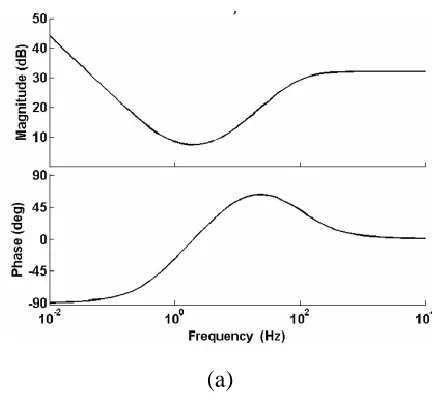
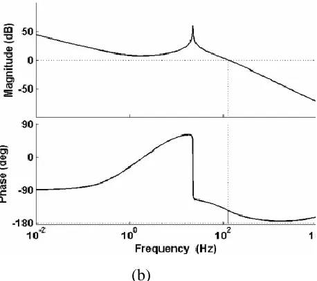
The zero and pole of the lead
compensator are designed to have a positive
phase margin and to restrict the crossover
frequency to about 14% of the switching
frequency. The bode plot of the PI controller
along with the lead compensate or and the
loop gain of the battery current control loop
are shown in Fig. 4(a) and (b). As shown in
Fig. 4, the phase margin is 34.2◦ at 130 Hz.
The output of the lead compensator
determines inductor current reference for the
dc–dc converter.
In order to prevent over loading the turbine
(and its consequent stalling) the lead
compensator output is first passed through
an adjustable current limiter. The lower limit
is set to zero and the upper limit is varied
according to the maximum power available
at a given wind speed. The output of this
limiter is used as the reference for the
current controller in the dc–dc converter.
Finally, in the inner most loop the
actual inductor current is made to track the
reference using peak current mode control
[21]. The compensated output of the
intermediate loop is compared with the
instantaneous inductor current of the buck
converter. The output of the comparator is
applied to an SR flip flop to produce the
gate pulses for the dc–dc buck converter.
The frequency of the clock pulses is 2 kHz.
The frequency of the gate pulse is equal to
the clock pulse frequency. This method of
generating gate pulses for the converter is
known as the current programmed control
technique. The advantage of this method is
that it does not allow the inductor current to
go beyond the rated limit. This in turn
protects the buck converter switch and
Inductor from over current situation.
(b)
Fig. 4. Bode plot of (a) PI controller in
cascade with lead compensator. (b) Loop
gain of the battery current control loop.
MODES OF BATTERY CHARGING:
A.CC Mode of Battery Charging:
In CC mode, the battery charging
current demand is determined from the
MPPT logic. MPPT is implemented by
comparing the actual and optimum TSR
(opt). The error is tuned by a PI controller to
generate the battery charging current as per
the wind speed. In this mode, the converter
output voltage rises with time while the
MPPT logic tries to transfer as much power
As possible to charge the batteries. The
actual battery charging current that can be
achieved does not remain constant but varies
with available wind speed subject to a
maximum of C/10 rating of the battery. The
battery charging current command has a
minimum limit of zero. In case the wind
speed is insufficient to supply the load even
with zero battery charging current the
inductor current reference is frozen at that
particular value and the balance load current
is supplied by the battery.
B. CV Mode of Battery Charging:
In the CC mode, the battery voltage
and SoC rise fast with time. However, the
charge controller should not overcharge the
batteries to avoid gasification of electrolyte
[14]. As a result, once the battery SoC
becomes equal to the reference SoC the
controller must switch over from CC mode
to CV mode. In CV mode, the battery
charging voltage is determined from the
buck converter output voltage (VO). The
value of the converter voltage when the
battery SoC reaches 98% is set as the
reference value and is compared with the
actual converter output voltage. The error in
the voltage is then controlled by a cascaded
arrangement of PI controller and lead
compensator to generate the inductor current
reference. It is then compared with the
comparator to generate gate pulses in a
similar way as described in Section A. In
this mode, the converter output voltage is
maintained at a constant value by the
controller action. So, in CV mode the
battery voltage and SoC rise very slowly
with time as compared to CC mode. The
battery charging current slowly decreases
with time, since the potential difference
between the buck converter output and
battery terminals gradually reduces.
Thus, in CC mode the buck
converter output current is regulated while
the output voltage keeps on increasing with
time. On the contrary in CV mode the output
voltage is regulated, while the current in the
circuit reduces gradually. To study the CC
and CV mode of battery charging, rated
value of wind speed Is applied to the system.
The battery parameters and the converter
Output parameters are observed with time.
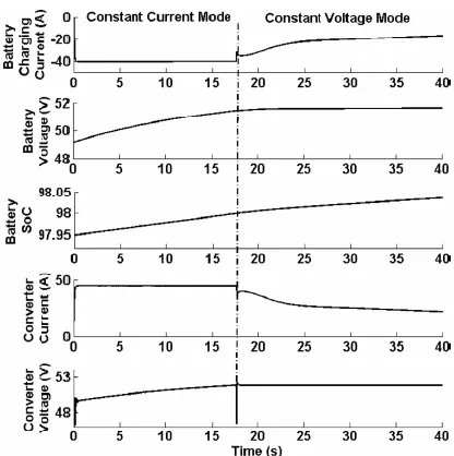
The results are shown in Fig. 5.
As shown in Fig. 5, the battery is
charged both in CC mode and CV mode.
The transition from CC to CV mode takes
place when the battery SoC reaches 98%.
This is because in the present design, the
threshold SoC for switch over in the control
logic is set at 98%. As discussed in the
earlier section, in the CC mode the battery
charges at a CC of 40 A which is the C/10
value for a 400-Ah battery bank. During this
mode, both converter output voltage and
battery voltage rise. The battery SoC rises
from an initial SoC level of 97.95% to 98%
within 17 s. As the battery reaches the
threshold SoC level, the buck converter
voltage is regulated by the controller action
at a constant value of 53 Vwhile the
converter current gradually reduces from 40
A at 17 sto 10 A at 40 s. The battery SoC
slowly rises from 98% to98.03%. The
results indicate that the battery charges at a
faster rate in CC mode as compared to CV
mode. Thus, in CC mode much of the
available power from primary source is
injected into the battery whereas in CV
mode the battery is charged slowly to avoid
Fig. 5. Battery charging modes at a constant
wind speed of 10 m/s.
Fig. 6.Cp −λ characteristics of the WT for
different pitch angles.
C. Pitch Control Mechanism:
The WT power output is
proportional to the cube of wind velocity
[15]. Generally the cut-off wind speed of a
modern WT is much higher compared to the
rated wind speed [9]. If the WT is allowed to
operate over the entire range of wind speed
without implementation of any control
mechanism, the angular speed of the shaft
exceeds its rated value which may lead to
damage of the blades. So, it is very much
essential to control the speed and power at
wind speeds above the rated wind speed.
This is achieved by changing the pitch angle
of the blade. Such
A mechanism is referred to as the pitch
control of WT.
The power coefficient (Cp) versus
TSR (λ) characteristics of the WT
considered in this study for different pitch
angles are shown in Fig. 6. As examined
from the characteristics, ata pitch angle of
zero degree the value of Cp is maxima. But
the optimum value of power coefficient
reduces with increase in pitch angle. This
happens because with increase in blade pitch
the lift coefficient reduces which results in
decreasing the value of Cp [15]. So, the
pitch control mechanism controls the power
output by reducing the power coefficient at
higher wind speeds. Below the rated wind
degree to obtain maximum power. The pitch
controller increases the blade pitch as the
WT parameters exceed the rated value. The
reduction in the value of Cp by pitching
compensates for the increase in WT power
output under the influence of higher wind
speeds. Apart from regulating the WT
parameters, it is also essential to control the
output voltage of the ac–dc rectifier to avoid
overvoltage condition in the WECS. Hence,
the pitch controller ensures that with
desirable pitch command, the WT
parameters and the rectifier output dc
voltage are regulated within their respective
maximum allowable limits to ensure safe
operation of the WECS.
CONCLUSION
The power available from a WECS is very
unreliable in nature. So, a WECS cannot
ensure uninterrupted power flow to the load.
In order to meet the load requirement at all
instances, suitable storage device is needed.
Therefore, in this paper, a hybrid
wind-battery system is chosen to supply the
desired load power. To mitigate the random
characteristics of wind flow the WECS is
interfaced with the load by suitable
controllers. The control logic implemented
in the hybrid set up includes the charge
control of battery bank using MPPT and
pitch control of the WT for assuring
electrical and mechanical safety. The charge
controller tracks the maximum power
available to charge the battery bank in a
controlled manner. Further it also makes
sure that the batteries discharge current is
also within the C/10 limit. The current
programmed control technique inherently
protects the buck converter from over
current situation. However, at times due to
MPPT control the source power may be
more as compared to the battery and load
demand. During the power mismatch
conditions, the pitch action can regulate the
pitch angle to reduce the WT output power
in accordance with the total demand.
Besides controlling the WT characteristics,
the pitch control logic guarantees that the
rectifier voltage does not lead to an over
voltage situation. The hybrid wind-battery
system along with its control logic is
developed in MATLAB/SIMULINK and is
tested with various wind profiles. The
outcome of the simulation experiments
validates the improved performance of the
system.
[1] A. D. Sahin, “Progress and recent trends in wind energy,” Progress inEnergy
Combustion Sci., vol. 30, no. 5, pp. 501–
543, 2004.
[2] R. D. Richardson and G. M. Mcnerney, “Wind energy systems,” Proc.IEEE, vol. 81,
no. 3, pp. 378–389, Mar. 1993.
[3] R. Saidur, M. R. Islam, N. A. Rahim, and K. H. Solangi, “A review onglobal wind energy policy,” Renewable Sustainable
Energy Rev., vol. 14,no. 7, pp. 1744–1762,
Sep. 2010.
[4] M. T. Ameli, S. Moslehpur, and A.
Mirzale, “Feasibility study for
replacingasynchronous genrators with
synchronous generators in wind farmpower
stations,” in Proc. IAJC – IJME, Int. Conf.
Eng. Technol., MusicCity Sheraton,
Nashville, TN, US, ENT paper 129Nov. 17–
19, 2008.
[5] G. K. Singh, “Self-excited generator
research—A survey,” Electric PowerSyst.
Res., vol. 69, no. 2/3, pp. 107–114, 2004. [6] R. C. Bansal, “Three-phase self-excited
induction generators: Anoverview,” IEEE
Trans. Energy Convers., vol. 20, no. 2, pp.
292–299,Jun. 2005.
[7] S. C. Tripathy, M. Kalantar, and N. D. Rao, “Wind turbine driven self-excited induction generator,” Energy Convers.