Design and Implementation of Ball and Beam
Control System
Vipulkumar D. Jadhav1, Dipak P. Bhapkar2, Mayuri P. Rane3, Dr Rajendra D. Kokate4
U.G. Student, Department of Instrumentation Engineering, Government College Engineering, Jalgaon, India1,2,3 Professor, Department of Instrumentation Engineering, Government College Engineering, Jalgaon, India4
ABSTRACT: The ball and beam control system usually defined as non-linear control system which basically derived
and implemented to observe the controller performance. One important step in this design process is to develop a mathematical model of the system. The main purpose of this project is to balance ball on beam using proportional– integral-derivative (PID) controller design with MATLAB and related control algorithm to adjust the angle of beam with real time sensory feedback. A constant angle of beam causes the ball to slide in axial direction due to gravity. Based on closed loop real time control system and well-tuned parameter, it will necessarily adjust angle of the beam to minimise the error, namely the distance between the actual position and set-point position of the ball. The system includes a ball, a beam, a motor and ultrasonic sensor for position sensing of ball. The basic idea is to use the torque generated from motor to the control the position of the ball on the beam by actuating the beam in desired angle. The information from the ultrasonic sensor can be taken and compared with desired set values and the difference can be fed back to Arduino used as controller that is PID controller design in it. Servo Motor will be interfaced with Arduino Uno board which in turn actuate the beam in desired angle in order to attain the set-point requirement.
KEYWORDS: Proportional-Integral-Derivative (PID) controller, MATLAB, Arduino uno, Mathematical modelling,
Transient parameters.
I. INTRODUCTION
II.LITERATURE SURVEY
Previously, the ball and beam system has been built by many organisations. In the following, a brief literature review is presented.
Hirsch (1999) built his ‘Ball on Beam System’ in 1999. The system employed an ultrasonic sensor to measure the position of the ball. The angle of the beam was measured though the use of a potentiometer. The motor with a gearbox was driven with a high power op-amp circuit. The system is controlled by a PD controller [2].
Arroyo (2005) built the system named the ‘Ball on Balancing Beam’ in 2005, the system employed the resistive wire sensor to measure the position of the ball. The resistive position sensor acted as a wiper similar to a potentiometer resulting in the position of the ball. The signal from the sensor was processed in a DSP. A DC motor with reducing gear was used. The system was controlled by PD controller.This system was easy to build, and the simple PD controller was easy to design. The negative aspects of the ‘Ball on Balancing Beam’ system includes that the beam was made of acrylic, which may be too brittle for a sudden impact. Additionally, although the position of the ball was controlled by the PD controller, the tilt angle of the beam was not measured and controlled. Therefore, the system may be not very robust. [2]
Another one from the Department of Electrical Engineering at Lakehead University built a system named the ‘Ball and Beam Balancer’ (Ambalavanar, Moinuddin & Malyshev 2006), The system employed a DC motor with an integrated gearbox, a resistive wire position sensor, and a digital encoder. The system was controlled by LQR controller.These ‘Ball and Beam Balancer’ system had one input (voltage input of the motor), and two outputs (the position of the ball and the tilt angle of the beam). The system may be very robust because the state space method with the LQR controller is good at controlling MIMO (Multiple Input, Multiple Output) system. The beam of the ‘Ball and Beam Balancer’ system was heavy because it was made of aluminium, which has a high density compared to acrylic [2].
III.SYSTEM CONFIGURATION
Fig(a) Final Configuration
We have used medium ranged heavy material like light stainless steel for beam build up because it satisfies motor operate with its equalise torque specification, with size of 40 cm. The main design objective of the final model was to create a structure that is not only sturdy and well balanced, but is also light-weight and portable to carry. Thus, it was determined that the best option was to select light metal because of it not only helps to portable manner but also it helps to motor operate with its equalise torque specification. Also it designed in simple construction and low cost.
IV.COMPONENTS OF THE SYSTEM
Ultrasonic Sensor: There are several position sensors which are suitable for this project. They are conductive plastic or resistive wire (nickel-chromium), ultrasonic range sensor. Here in our project we have used ultrasonic range sensor which measures distance between ball and itself that is the position of ball and fed this signal to the controller. Hence we have used the Ultrasonic ranging module HC - SR04 provides 2cm - 400cm non-contact measurement function, the ranging accuracy can reach to 3mm. The modules include ultrasonic transmitters, receiver and control circuit. The basic principle of work of this sensor is on time difference basis that is by generating an ultrasonic wave or pulse and measuring a time it takes for echo to return.
MG995 Servo Motor: Basically, motor is a device that changes electrical energy into mechanical energy. It plays the
most important part of the ball and beam control system as actuator for beam to tilt the beam in desired angle to attain the balls position at required set-point. A cheap, linear motor with good Controllability is necessary for this application. A servo motor with an integrated gearbox used for this system. In our project we have used MG995 servo motor which is the most famous servo made by TowerPro.MG995 is a digital metal gear high torque servo for airplane, helicopter.
Arduino Uno Board: Arduino is an open-source prototyping platform based on easy-to-use hardware and
V.MATHEMATICAL MODELLING OF SYSTEM
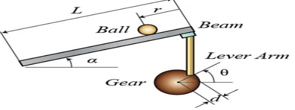
Theoretical Analysis: A ball is placed on a beam, see figure below Fig (b)Theoretical Configuration, where it is
allowed to roll with 1 degree of freedom along the length of the beam. A lever arm is attached to the beam at one end and a servo gear at the other. As the servo gear turns by an angle theta, the lever changes the angle of the beam by alpha. When the angle is changed from the horizontal position, gravity causes the ball to roll along the beam. A controller will be designed for this system so that the ball's position can be manipulated [5].
Fig (b) Theoretical Configuration
This is theoretical analysis for ball and beam control system shown in fig (a) Theoretical configuration considering with all variables and constants affecting to this control system which describes system behaviour in the form of transfer function with help of The Lagrangian equation of motion.
The constants and variables for the above system are defined as follows as:
(m) Mass of ball (in kg) (L) Length of beam (in m)
(R)Radius of ball (in m) (J) Balls moment of inertia (in kg.m2) (d) Lever arm offset (in m) (r) Ball position coordinate
(g) Gravitational acceleration (in m/s2) (Alpha α) Beam angle coordinate
(theta Ø) Servo gear angle
The second derivative of the input angle alpha actually affects the second derivative of r. However, we will ignore this contribution. The Lagrangian equation of motion for the ball is then given by the following [5]
0 = + ̈+ sin − ̇
The beam angle ( ) can be expressed in terms of the angle of the gear ( ). [5]
= Ø
Building The Model In Simulink:
In this rather than express all the forces and geometric constraints we will model the nonlinear Lagrangian equation of motion directly. This equation gives as a function of the state and input variables,r, ̇,α,and ̇. We will make use of the Function block to express this function. First, we must express the derivatives of the output r. So, first of all open a new model window in Simulink. Insert an Integrator block. Insert a second Integrator to the right of the first, and connect the two with a line. Label the line connecting the two " / ( )". Draw a line from the second Integrator and label it "r". Insert an Out1 block and connect it to the "r" signal line. This will form the output of the system. Change the label of the Out1 block to "r". Now, we will insert the function which takes the vector [ ̇ ̇] and returns ̈. Insert a Functionblock and connect its output to the input of the first Integrator. Edit
the Function block, and change its function to the following [5]:
̈= − 1
+ ( sin −
̇
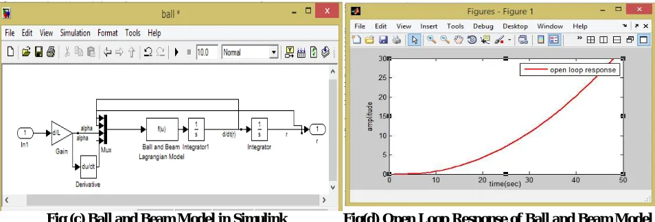
This function block takes an input vector, u, where each component is referred to as u [1], u [2] etc. In our case u [1] =r, u [2] = ṙ, u [3] = αand u [4]= ά. Then change the label of the Function block to "Ball-Beam Lagrangian Model". Then, we will begin to construct the function input vector u by feeding back the state signals from the integrators and forming a vector from them with a Mux block. Insert a Mux block and connect its output to the input of the Ball-Beam block. Edit the Mux block and change its number of inputs to 4. The Mux block should now have four inputs. Tap a line off the d/dt(r) signal and connect it to the second input of the Mux block. Tap a line of the r signal and connect it to the first input of the Mux block. Then we will construct the signals and ̇ from the input Ø. Insert an In block on the left side of your model window. Change its label to "theta". Insert a Gain block and connect it to the theta block. Change its gain value to “d/L’. Connect the output of the gain block to the third input of the Mux block. Label this line "alpha". Insert a Derivative block and place it underneath the alpha signal line. Tap a line off the output of the Gain block and connect it to the input of the Derivative block. Connect the output of the Derivative block to the fourth input off the Mux block. So, overall model will show like in following way in fig(c)Ball and Beam Model in Simulink this overall model forms total theoreticalproject model which energise with step input and generates the final response that is open loop response as its own behaviour.
Open-Loop Response:To generate the open-loop response, it is helpful to first contain this model in a subsystem block.
Insert Subsystem block and open the Subsystem block and copy the previous model named ball.mdl and paste in it. Then Close the Subsystem window. You will see the Subsystem block in the untitled window with one input terminal labelled ‘theta’ and one output terminal labelled ‘r’.
(a)Obtaining Transfer Function Of System:
Before obtaining a step response, we must set the physical parameters as taken and entered them in MATLAB command window.
m=0.187; L=0.4;
R=0.02; J=9.99e-6;
d=0.03;
Fig (c) Ball and Beam Model in Simulink Fig(d) Open Loop Response of Ball and Beam Model
Extracting The Linear Model Into Matlab:
The Simulink model can be extracted into an equivalent state-space or transfer function model in MATLAB. This is done through the use of In1 and Out1 blocks and the MATLAB function linmod.
For this purpose, enter the following commands in MATLAB’s command window. You will see the following output providing the open-loop model of the system [5].
[A,B,C,D] = linmod(‘ball’) [num, den] = ss2tf(A,B,C,D)
And getting the transfer
function-0.0546
VI. BUILDING PID CONTROLLER FOR THE SYSTEM
As we seen earlier the system is non-linear. So we have need a controller to make it linear and force it to work desirably. To design the PID controller further steps are to be followed. Insert a step block and keep the step time as zero. Insert an PID block and set initial values of kp ,ki and kd as zero. Insert scope and signal constraint block from sink
and Simulink design optimization library respectively. Insert a transfer function block and implement the transfer function found in above case there. The main purpose of signal constraint to set the constraint to get the response as per our desire. We can set the constraints for the response in that pallet. Now go to signal constraint palate, set the response constraints and start the simulation. The signal constraint shows various step responses in reference to ideal step response curve and finally it settled as ideal step response curve which is shown below [5]. And it gives closed loop response as shown in below fig(e) as well as the final settled response obtained in scope is shown below in fig(e). During the process, It optimise the kp ki and kd values with changing number of iterations. Finally, it gives the optimum
values of kp ki and kdwithin specified tolerance.
In this way, we have finally got this kp ki and kd values. Which we have used as gain parameters in ‘my.PID’ wallet of
Arduino. The obtained values of kp ki and kd are given below
This Fig(e) Building of PID controller for the system and its controlled closed loopresponse demonstrates building of PID controller for the system and response of system after PID action is consequences on the ball and beam mathematical model and generates final system controlled response that is closed loop response of the system.
Fig(e) Building of PID controller for the system and its controlled closed loop response
VII.CONNECTION AND WORKING
Basically it operates as in closed loop control system shown in fig (f) Block Diagram of Ball and Beam Control Systemin which, Set point gives as reference signal to PID controller takes corrective action according to feedback signal received by ultrasonic sensor and controls the ball and beam model as final balls position to set point.
Fig(f) Block Diagram of Ball and Beam Control System
plotter option provided in that version of same software. Thus, in terms of servo actuation we have provided control signal to servo motor from pin no. 9 i.e. PWM signal which is suitable for servomotor.
Basically this system referred as very non-linear system. Its main objective to design accurate controller and apply different control strategies for that system in order to get better control over the system and stabilize it in less amount of time. As per setup and objective which has to be achieve we have developed the programming code. In which First of all, set the maximum and minimum range for balls position to rolls over the beam that is min is 2cm and maximum is 40cm and also set the limits of the angle of rotation that is in range between -45 to +45. Moving towards the controller, which has near about perfect values of the Kp, Ki and Kd as we had calculated from tuning which will
consider as it got better control over the system but whenever it loses the control over system then we had to change the gain parameters according to system stabilization.
Initially controller requires the initial position of the motor for that purpose we had to measure the initial angle of the servomotor and gives it to the controller for better control because, until controller didn’t know the initial angle of the servomotor It cannot be get control over the system. Normally, all of the ‘ball on beam balancing control system’ project has used encoder. Which directly acts as angle sensor for servomotor and it gives directly initial angle to PID controller. But, because of the cost effective reason we could not implement the position sensor as encoder. Hence for that solution we have developed another technique which helped directly to indicate servomotor angle. Which is also cheap technique to measure the angle of the servomotor.
Potentiometer directly connected to the one of the analog input pin of arduino (A1) as varying analog input resistance among the circuit of power supplying to servomotor. And servomotor connected to PWM output pin no. 8 which vary the pulse width according to input resistance changes through POT. As the wiper of the POT rotates from 0 to 360 degree it changes its resistance proportionally. As resistance changes servomotor rotates from angle 0 to 180 degree. And normally this value in arduino plots as 0 to 1023 then it mapping to 0 to 180 degree that is movement in angle of rotation. Basically, this 0 to 180degree value plotted as input analog value of POT resistance. And hence according to that movement of the wiper it directly calibrated as angle of the servomotor.
VIII.RESULT
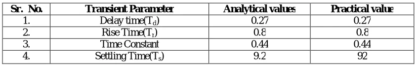
As we have worked our configuration, we have attained stability in 92 sec. with our system at 15 cm set-point. We had simulated our system with ‘Serial plotter’ function in arduino which shows real time varying parameter with respect to the time as shown in below. The process of taking the distance measurements by ultrasonic sensor and comparing the same with setpoint continues until ball attains desired position.From the above resulted closed loop response in Simulink of Matlab we have calculated theoretically analytical transient parameters and practically worked analytical transient parameters which shown in below table no.1 Theoretically and Practically Calculated Transient parameters.
The Transient Parameters are given below,
Table No.1 Theoretically and Practically Calculated Transient parameters
Sr. No. Transient Parameter Analytical values Practical value
1. Delay time(Td) 0.27 0.27
2. Rise Time(Tr) 0.8 0.8
3. Time Constant 0.44 0.44
4. Settling Time(Ts) 9.2 92
PID parameters kp, ki, kd or variation in system parameters, imperfect mechanically designed system with wear and tear
at joints etc.
IX.CONCLUSION
Thus from our project we have concluded that the Ball and Beam system is most non-linear system available to us after aeroplane and it is best platform to check the controller performance. If any controller works well with system then that controller is fine. But, if any controller doesn’t respond as per our desire then some modifications are needed in the same. Also the controller we have designed is not that perfect since it took lot of time to attain steady state because of it affected by many constraints like PID parameterskp, ki, kd, absolutely correct system parameters,
mechanical design consideration etc.
REFERENCES
[1] Elmerabete, J. Hong Li Rafi, Y. “Application of Real-Time Control System Using MATLAB in Distance-Learning” International Conference on Measuring Technology and Mechatronics Automation (ICMTMA)”, Volume. 1,663 – 666, 2010,
[2] Wei Wang, “Master thesis project- Ball and Beam”, School of Mechanical Engineering, The University of Adelaide, June- 2006,. [3] “Modelling of Ball and Beam System”, www.Mathworks.com, march 22, 2017
[4] Tipsuwanpom, Runghimmawn, T Runghim, T. Intajag, and S. Krongratana "Ball and Beam module," Industrial Electronics, 2006 IEEE International Symposium, Vol.2, No.11,1495- 1500, 2006,.
[5] Korrapati R.; Anderson, J.A; Swain, N.K; Swain M; “System Modeling Using Virtual Instruments”,Proceedings IEEE Digital Object Identifier, Southeast Con, 2002. 121 – 12. 2002,
[6] N. Kehtarnavaz, N. Kim, and I. Panahi, Digital signal processing system design using Arduino and TMS320C6000, IEEE Digital Signal
Processing Workshop, 2004.
[7] Norman S. Nise.”Control Systems Engineering”,John Wily & Sons, Inc., 4th edition, 2004,.