R E S E A R C H
Open Access
Joint optimization of source and relay
precoding for AF MIMO relay systems
Jun Li
1, Xueqin Jiang
2, Sangseob Song
1, Ying Guo
3and Moon Ho Lee
1*Abstract
In this paper, we investigate a joint source and relay precoding design scheme for an amplify-and-forward (AF) multiple-input multiple-output (MIMO) relay system with absence of the direct link. The joint optimization problem, which is to minimize an objective function based on the mean square error (MSE), is formulated as a nonconvex optimization problem in the AF MIMO relay system. Instead of the conventional iterative method, we use an inequality to derive a lower bound of the MSE under the power constraint for obtaining a suboptimal solution of the objective function, which makes the optimization problem convex and also approaches the existing upper bound of the MSE, especially at the high signal-to-noise ratio (SNR). Numerical results show that this scheme outperforms the previous schemes in terms of either MSE or bit error rate (BER).
Keywords: Amplify-and-forward (AF) multiple-input multiple-output (MIMO) relay; Joint precoding; Lower bound
Introduction
As the relay channel was initially introduced in wire-less networks [1, 2], the cooperative relay communication has been developed rapidly these days [3]. The known relay protocols have been classified as amplify-and-forward (AF), decode-and-amplify-and-forward (DF), and compress-and-forward (CF) [4].
Compared with DF and CF protocols, the AF proto-col suffers from the noise enhancement, but it is still considered as a hot issue in wireless networks since it usually leads to low complexity and low consumption of power. On the other hand, the input multiple-output (MIMO) technology was introduced to increase the channel capacity and improve the reliability of wireless networks in [5]. Therefore, using the MIMO technology into a relay system and the optimization design in the MIMO relay system have gained much attention [6].
The main optimizing processing of an AF MIMO relay system is to maximize or minimize objective func-tions, such as mutual information (MI), mean square error (MSE), sum of rate and signal-to-interference-plus-noise ratio (SINR). For example, Fang et al. proposed an approach to maximize the MI for an optimal design of
*Correspondence: [email protected]
1Department of Electronics and Information Engineering, Chonbuk National University, Baekje Road, Jeonju, South Korea
Full list of author information is available at the end of the article
source covariance matrix and relay matrix [7]. Similar results were achieved while taking a source covariance matrix as an identity matrix [8, 9]. In addition, an opti-mization of the joint power constraint was designated to maximize the MI [10]. The minimization of the MSE for MIMO relay systems was derived for a joint optimal design of source matrix and relay precoding matrix [11]. Furthermore, unified frameworks were developed to opti-mize the source and relay precoding matrix while design-ing an iterative algorithm to allocate the optimal power to the relay channels [12]. Due to the high computational complexity of the iterative algorithm, a suboptimal algo-rithm was also developed to reduce its computational complexity [13, 14]. As for the precoding multi-relay net-works, the joint source-relay optimization design was proposed to maximize SINR [15]. The optimization of achievable rate and channel capacity was also derived [16]. Moreover, the optimizations of two-way relay systems were investigated using the precoding approach in a sim-ilar scenario as the previous literatures [17–19]. For the optimization of the AF MIMO relay systems, Sanguinetti et. al. not only summarized various kinds of optimization problems but also suggested several related solutions for each problem [20].
In this paper, we suggest a joint optimal design of the source and relay precoding matrices for AF MIMO relay
systems. For simplicity, we assume that the perfect chan-nel state information (CSI) is available at the relay and destination. We will derive an objective function on the basis of the MSE. Since the proposed objective function is not convex, we further derive a lower bound of the objec-tive function to make it convex which is different from the upper bound in [14]. The numerical results show that the lower bound has a better performance than the previous schemes. It approaches to the known upper bound at the high signal-to-noise ratio (SNR).
The rest of this paper is organized as follows. In the “System model” section, we introduce the system model for the AF MIMO relay system. The lower bound of the MSE is derived in the “Lower bound of MSE” section. In the “Numerical results” section, numerical results are pre-sented. The “Conclusions” section concludes this paper.
Notations: Boldface upper- and lowercase letters denote matrices and column vectors, respectively.(·)H stands for
Hermitian transpose. Crepresents the complex number field. IM is an identity matrix of sizeM×M.CN(μ,ν)
stands for the complex Gaussian distribution with mean μand covarianceν.E{·}denotes the expectation operator. tr{·}andrank{·}denote the trace and rank of a matrix.Aij
denotes the(i,j)-th element of matrixA.(·)−1stands for matrix inversion.∇2(·)denotes the second-order gradient of a function.(·) 0 stands for a semi-positive definite matrix.
System model
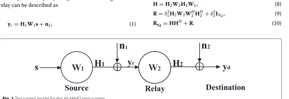
We consider an AF MIMO relay system as shown in Fig. 1, where the source, the AF relay and the destination are equipped withNs,NrandNdantennas, respectively. The
half-duplex mode is used for this system, where each node cannot transmit and receive simultaneously. The direct link is not considered and the flat fading is applied for all channels.
The transmission will take two time slots. In the first time slot, the source transmits a symbol vectors∈CK to the relay, whereE{ssH} = IK. The received signal at the
relay can be described as
yr=H1W1s+n1, (1)
whereH1 ∈CNr×Ns denotes the channel matrix between the source and the relay,W1∈CNs×Kdenotes the source precoding matrix and n1 denotes a Gaussian noise vec-tor withn1∼CN(0,δ12INr). For the simplicity, the power
constraintP1at the source is given by
trW1W1H
≤P1. (2)
In the second time slot, the relay forwards the received signal after using a precoding matrixW2∈CNr×Nr. With the power constraintP2at the relay, we can obtain
trW2
H1W1WH1HH1 +δ12INr
WH2≤P2. (3) Subsequently, the received signal at the destination can be derived as
yd=H2W2H1W1s+H2W2n1+n2, (4) whereH2∈CNd×Nrdenotes the channel matrix between the relay and the destination andn2denotes a Gaussian noise vector with n2 ∼ CN(0,δ22INd). In the end, a
lin-ear receiver G ∈ Ck×Nd is applied at the destination. Therefore, the estimated signal at the destination can be achieved as
¯
s=Gyd. (5) Lower bound of MSE
In order to derive an optimization processing with a lower bound for the AF MIMO relay system, we consider the MSE matrix given by
M(W1,W2)=E
(¯s−s)(¯s−s)H
=EGydydHGH−GydsH−sydHGH
+I. (6) Substituting (4) and (5) into (6), we obtain
M(W1,W2)=GRydG
H−GH−HHGH+I, (7)
where the whole channel matrixH, the noise covariance matrixRand the covariance matrix of the received signal
Rydare described as follows
H=H2W2H1W1, (8)
R=δ12H2W2W2HHH2 +δ22INd, (9)
Ryd=HH
H+R. (10)
3 4 5 6 7 8 9 10 0.2
0.3 0.4 0.5 0.6 0.7 0.8 0.9
SNR
s(dB)
AMSE
NAF PMF Upper bound Lower bound
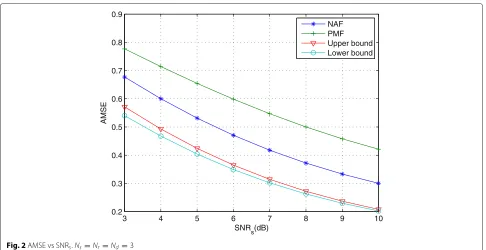
Fig. 2AMSE vs SNRs.Ns=Nr=Nd=3
The matrix Gto minimize the MSE matrix is given by Wiener filter, i.e.,
G=(H)H(HHH+R)−1. (11) By substituting (11) into (7), the minimal MSE matrix can be derived as
M(W1,W2)=I−HH(HHH+R)−1H
=(HHR−1H+IK)−1, (12)
which is achieved on a basis of the matrix inversion transformation
(A+BCD)−1=A−1−A−1BDA−1B+C−1−1DA−1. (13)
In what follows, we will consider how to minimize the MSE matrix for the AF MIMO relay system. The arith-metic MSE (AMSE) [12] is given by
AMSE=
K
i=1
[M(W1,W2)]i,i, (14)
where the MSE matrixMis chosen as a diagonal matrix. Then the SINR [21] can be expressed as
SINR=
K
i=1
1
[M(W1,W2)]i,i −
1
. (15)
It implies that minimizing the MSE is equivalent to max-imizing the SINR. Also, the symbol error rate [22] can be described as
Pe(SINR)=αQ βSINR
, (16)
where α andβ are constants that depend on the signal constellation, andQis theQ-function defined asQ(x) = (1/√2π)x∞e−λ2/2dλ. Namely, minimizing the symbol error rate or bit error rate is also equivalent to minimizing the MSE. Using the abovementioned analysis, the optimal processing can be derived as
min W1,W2
[M(W1,W2)]i,i, 1≤i≤K, (17) s.t. trW1W1H
≤P1, trW2
H1W1WH1HH1 +δ12INr
WH2≤P2. Let us denote the singular value decomposition (SVD) of channelsH1andH2as
H1=U11VH1, (18) and
H2=U22VH2, (19) where U1, V1, U2 and V2 are unitary matrices, while 1and2are the diagonal matrices with entries being arranged in the non-increasing order [10]. In order to make the MSE matrix as a diagonal matrix, the optimal matricesW1andW2should be chosen as [12]
W1= ¯V1 1, (20) and
3 4 5 6 7 8 9 10 10−5
10−4 10−3 10−2 10−1 100
SNR
s(dB)
BER
NAF PMF Upper bound Lower Bound
Fig. 3BER vs SNRs.Ns=Nr=Nd=3
Substituting (18)–(21) into (11), the MSE matrix can be calculated as follows
M( 1, 2)=
IK + ¯ 2
1¯22 12 22 δ2
2IK +δ12¯22 22 −1
, (22)
where 1¯ and 2¯ denote the diagonal matrices that contain the firstK columns of1and2, respectively.
Therefore, the optimization problem of the AMSE can be rewritten as
min
σ1,k,σ2,k K
k=1
1+ λ 2
1,kλ22,kσ1,2kσ2,2k δ2
2+δ21λ22,kσ2,2k −1
, (23)
whereσ1,k,σ2,k,λ1,kandλ2,kdenote thekth diagonal entry
of 1, 2,1, and2, respectively, ∀k ∈ {1, 2,. . .,K}.
3 4 5 6 7 8 9 10
0.2 0.3 0.4 0.5 0.6 0.7 0.8 0.9 1
SNR
s(dB)
AMSE
NAF PMF Upper bound Lower bound
3 4 5 6 7 8 9 10
The whole channel can be divided into K subchannels with the joint precoding approach where each subchan-nel gain can be specified asλ21,kλ22,k, while 1and 2can be treated as the power allocation. It is obvious the power allocation is a key parameter for the optimization in the AF MIMO relay system. After substituting (20) and (21) into the power constraint (17), we obtain
σ2
stream at the source and the relay, respectively. Further-more, taking λ¯21,k = λ21,k/δ12 and λ¯22,k = λ22,k/δ22 and replacingσ1,k,σ2,k,λ1,k andλ2,k in (23), the optimization
problem can be expressed as follows
min
It is obvious that the abovementioned objective function is not convex [10]. Namely, it is difficult to get the optimal solution from (26). Although Rong et al. [12] has proposed an iterative algorithm for the optimal solution, the com-putational complexity is still very high. In order to reduce the computational complexity, an upper bound as a sub-optimal solution was derived [14], where we can get the
very close performance to an iterative algorithm. In the following, we will propose a lower bound to achieve the better performance but having a little high computational complexity comparing with the upper bound.
There are two known conventional bounds given by
x+y+1
positive values in our system, it is suitable to use the two bounds into the objective function. We substitute (27) into the objective function (26) and an upper bound can be calculated as
and
The abovementioned suboptimal solutions are developed by Rong with the MMSE criterion [14]. On the other hand, the lower bound can be similarly derived by using the inequality (28), where the lower bound can be denoted by f(x,y) = (x+y)/(x+y+xy). It can be proved that this lower bound is a convex function, i.e.,
∇2f(x,y)= 2
In the following, we derive another suboptimal solution which can be written as
min
Taking the Karush-Kuhn-Tucker (KKT) conditions [23], we get the solution of the optimization problem, which yields an equivalent function
F=
whereυ1andυ2are the Lagrange multipliers. After mak-ing the tedious partial derivatives of equation (34), the solution of the unknown parameters(a1,a2,. . .,ak)and (b1,b2,. . .,bk) can be derived. Because of the partial
derivatives in the calculation, the computational complex-ity of the lower bound is a little higher than that of the upper bound.
Numerical results
In this section, we analyze the derived lower bound for the AF MIMO relay system. The two-channel matrices are assumed to be distributed withCN(0, 1). The SNRs at the relay and the destination are defined as SNRs = P1/σ12
and SNRd=P2/σ22, respectively.
We compare the upper bound of the proposed scheme with the initial amplify-and-forward (NAF) algorithm [12] or Pseudo match-and-forward (PMF) algorithm [24]. In the NAF-based scheme, the source precoding matrix is given by
W1=
P1
KIK, (35)
and the relay precoding matrix is described as
W2=
In order to compare with the PMF-based scheme, we takeNs=Ndin the following analysis. Firstly, we consider
a case of the same number of antennas at each node. With-out loss of generality, we assume thatNs =Nr =Nd= 3
andK = 2. Figure 2 shows the AMSE of all algorithms for the fixedρ2 = 10 dB. The BER performance of the algorithms is demonstrated in Fig. 3. It is shown that the derived lower bound of the joint precoding scheme has a better performance than that of either NAF-based or PMF-based scheme. Comparing the lower bound with the upper bound, the difference of the AMSE is reduced as the SNR increases, which is shown in Fig. 2, and the two curves are almost overlapped at SNR around 10 dB. How-ever, the BER performance of the lower bound is slightly different from the upper bound, as shown in Fig. 3.
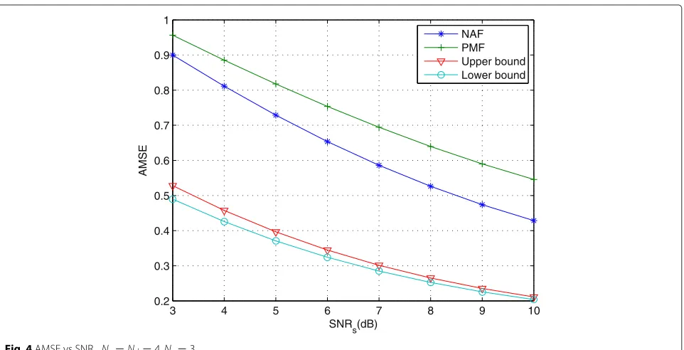
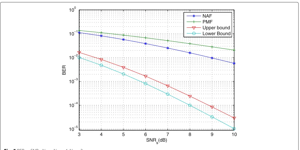
Subsequently, we consider another case of the different number of antennas. We takeNs = Nd = 4,Nr = 3 and K = 2 in the simulations. The numerical results of the AMSE and the BER of the related algorithms are shown in Figs. 4 and 5, respectively. We also find that the lower bound is still superior than that of the previous schemes. The derived lower bound and upper bound approach each other, especially at the high SNR. This is consistent with the case of the same number of antennas. It implies that the derived lower bound is approaching to the true objec-tive curve at the high SNR. In other words, the accuracy of the proposed lower bound is great guaranteed with the increment of the SNR.
Conclusions
Competing interests
The authors declare that they have no competing interests.
Acknowledgements
This work was supported by MEST 2015R1A2A1A05000977, NRF, South Korea, National Nature Science Foundation of China (61201249, 61359153, 61272495), and the Brain Korea 21 PLUS Project, National Research Foundation of Korea.
Author details
1Department of Electronics and Information Engineering, Chonbuk National
University, Baekje Road, Jeonju, South Korea.2School of Information Science
and Technology, Donghua University, Shanghai, China.3School of Information
Science and Engineering, Central South University, Lushangnan Road, Changsha, China.
Received: 20 November 2014 Accepted: 7 May 2015
References
1. EC Van Der Meulen, Three-terminal communication channels. Adv. Appl. Prob.3, 120–154 (1971)
2. TM Cover, AEL Gamal, Capacity theorems for the relay channel. IEEE Trans. Inform. Theory.25(5), 572–584 (1979)
3. P Gupta, PR Kumar, The capacity of wireless networks. IEEE Trans. Inform. Theory.46(2), 388–404 (2000)
4. JN Laneman, DNC Tse, GW Wornell, Cooperative diversity in wireless networks: Efficient protocols and outage behavior. IEEE Trans. Inform. Theory.50(12), 3062–3080 (2004)
5. IE Telatar, Capacity of multi-antenna gaussian channels. European Trans. Telecom.10(6), 585–595 (1999)
6. C Chae, T Tang, RW Heath, S Cho, MIMO relaying with linear processing for multiuser transmission in fixed relay networks. IEEE Trans. Signal Process.56(2), 727–738 (2008)
7. Z Fang, Y Hua, JC Koshy, inFourth IEEE Workshop on Sensor Array and Multichannel Processing. Joint source and relay optimization for a non-regenerative MIMO relay, (2006), pp. 239–243
8. X Tang, Y Hua, Optimal design of non-regenerative MIMO wireless relays. IEEE Trans. Wireless Commun.6(4), 1398–1407 (2007)
9. O Muñoz-Medina, J Vidal, A Agustín, Linear transceiver design in nonregenerative relays with channel state information. IEEE Trans. Signal Process.55(6), 2593–2604 (2007)
10. I Hammerstrom, A Wittneben, Power allocation schemes for amplify-and-forward MIMO-OFDM relay links. IEEE Trans. Wireless Commun.6(8), 2798–2802 (2007)
11. W Guan, H Luo, Joint MMSE transceiver design in non-regenerative MIMO relay systems. IEEE Commun. Letters.12(7), 517–519 (2008)
12. Y Rong, X Tang, Y Hua, A unified framework for optimizing linear nonregenerative multicarrier MIMO relay communication systems. IEEE Trans. Signal Process.57(12), 4837–4851 (2009)
13. Y Rong, inIEEE International Conference on Communications (ICC). Non-regenerative multicarrier MIMO relay communications based on minimization of mean-squared error, (2009), pp. 1–5
14. Rong, Y, Linear non-regenerative multicarrier MIMO relay
communications based on MMSE criterion. IEEE Trans. Commun.58(7), 1918–1923 (2010)
15. A Ikhlef, R Schober, Joint source-relay optimization for fixed receivers in multi-antenna multi-relay networks. IEEE Trans. Wireless Commun.13(1), 62–74 (2014)
16. TX Tran, NH Tran, HR Bahrami, S Sastry, On achievable rate and ergodic capacity of NAF multi-relay networks with CSI. IEEE Trans. Commun.62(5), 1490–1502 (2014)
17. Z Ding, T Wang, M Peng, W Wang, KK Leung, On the design of network coding for multiple two-way relaying channels. IEEE Trans. Wireless Commun.10(6), 1820–1832 (2011)
18. Z Zhao, M Peng, Z Ding, W Wang, HH Chen, Denoise-and-forward network coding for two-way relay MIMO systems. IEEE Trans. Veh. Technol.63(2), 775–788 (2014)
19. S Yadav, PK Upadhyay, S Prakriya, Performance evaluation and
optimization for two-way relaying with multi-antenna sources. IEEE Trans. Veh. Technol.63(6), 2982–2989 (2014)
20. L Sanguinetti, AA D’Amico, Y Rong, A tutorial on the optimization of amplify-and-forward MIMO relay systems. IEEE J. Selected Areas Commun.30(8), 1331–1346 (2012)
21. DP Palomar, JM Cioffi, MA Lagunas, Joint Tx-Rx beamforming design for multicarrier MIMO channels: a unified framework for convex optimization. IEEE Trans. Signal Process.51(9), 2381–2401 (2003)
22. JG Proakis,Digital Communications. (McGraw-Hill, New York, 1995) 23. S Boyd, L Vandenberghe,Convex Optimization. (Cambridge University
Press, Cambridge, 2004)
24. PU Sripathi, JS Lehnert, inIEEE Conference Record of the Thirty-Eighth Asilomar Conference on Signals, Systems and Computers. A throughput scaling law for a class of wireless relay networks, vol. 2, (2004), pp. 1333–1337
Submit your manuscript to a
journal and benefi t from:
7Convenient online submission 7Rigorous peer review
7Immediate publication on acceptance 7Open access: articles freely available online 7High visibility within the fi eld
7Retaining the copyright to your article