PREFACE
The purpose of this manual is to provide a comprehensive source of information concerning the UNIVAC
III System: its basic units, their performance, the performance of the system as a whole, and the in-struction list. The manual is addressed to those who have a good general knowledge of electronic com-puters and therefore can appreciate the significance of the uniquely powerful features of the system without detailed explanations or examples of the use of instructions or programming aids. Descriptions of software packages are available in separate publications.
For years the goal of designers of electronic data-processing equipment has been to achieve a system the units of which could operate not only simul-taneously but also at their full rated speeds. Now, with the UNIVAC III System, this goal has been attained. This system is capable of performing calculations and data manipulations and operating its peripherals at full speed, under the control of several concurrently running programs.
Briefly summarized here are some of the principal characteristics of the system which account for its unusual merit in general data-processing applications.
HIGH-SPEED MAGNETIC TAPES-Numeric read-write speed, 200,000 digits per second-alphanumeric read-write speed, 133,000 characters per second. A 3600-foot reel of tape can be rewound in 125 seconds. Scatter-read and gather-write operations permit direct transfer of magnetic-tape data to and from nonadjacent areas of magnetic-core storage. This obviates the need for many data-transfers and thus saves large amounts of time and storage space.
HIGH·SPEED PROCESSING-4-microsecond mem-ory cycle. The system executes most instructions in only 8 microseconds. In 12 milliseconds the UNIVAC III system can add 1000 12-digit numbers. Multi-plication and division are performed at correspond-ingly high speeds.
VERSATILE COMMAND STRUCTURE-The in-structions of the UNIVAC III System can address data directly or can indirectly address operands of up to four 6-digit words, thus saving many program-ming steps and much time on operations such as sorting and table referencing.
Using multiword operands and field selection, in-structions operate directly upon fields which may range in size from a single bit, digit, or character to 96 bits, 24 digits, or 16 characters, eliminating the need for isolation of packed fields or separately proc-essing each word of multiword fields. The effect of this is a large economy in programming and oper-ating time otherwise required for shifting, extracting, and data transfers.
The system may be provided with either 9 or 15 index registers which automatically modify the operand address as part of the basic instruction execution cycle-no additional time need be allo-cated to operate the registers.
SYSTEMS MODULARITY-The UNIVAC III System can be smoothly and efficiently expanded by adding up to four 8192-word core-storage modules to provide storage for up to 32,768 words; up to 32 UNISERVO IlIA magnetic-tape units; and an extensive and versatile array of peripherals.
SIMULTANEOUS OPERATIONS-As many as 13 on-line input-output operations can proceed in paral-lel with each other and with operations of the Central Processor under the control of several concurrently running programs.
HIGH.SPEED PERIPHERALS-High-Speed Reader -700 cards a minute; Card-Punch Unit-300 cards a minute; High-Speed Printer-922 128-character
lines of numeric data per minute or 700 128-character lines of alphanumeric data per minute.
DEPENDABILITY - The circuitry of the UNIVAC III System is based on that proved in use in the famous UNIVAC LARC, one of the fastest, most reliable computers ever built. The UNIVAC III System also contains many automatic self-checking features which ensure dependable operation.
CONTENTS
GEN ERAL DESCRI PTION
Central Processor I-I
Input-Output Equipment 1-4
II CENTRAL PROCESSOR
UNIVAC III Word 2-1
Programming Features 2-4
Automatic Program Interrupt 2-6
Control Unit 2-10
UNIVAC III Instruction List 2·13
Operator's Console 2-38
III TAPE SYSTEM
Physical Characteristics 3-2
Operating Characteristics 3-3
Function Specifications 3-6
Interrupt Indicators 3-10
Execution of Function Specifications 3-12
Control Features 3-13
IV HIGH-SPEED READER
Operating Characteristics 4-2
Function Specifications 4-7
Interrupt Indicators 4-9
Control Featu res 4-11
V CARD-PUNCH UNIT
Operating Characteristics 5-2
Function Specifications 5-8
Interrupt Indicators 5-9
Control Features 5-9
VI HIGH-SPEED PRINTER
Physical Characteristics 6-1
Operating Characteristics 6-2
Function Specifications 6-4
Interrupt Indicators 6-4
APPENDICES
A. Modulo-3 Checking
B. Execution Time of Multiplication C. Execution Time of Division
D. Decimal Operations on Non-Numeric Data E. Reading Nonstandard 80-Column
Card Codes With Translation F. High-Speed Printer Timing
G. Input-Output Equipment Specifications H. Fixed Memory Locations
I. Instructions and Functions Specifications
GENERAL DESCRIPTIDN
A typical basic UNIVAC III System comprises a Central Processor with magnetic-core storage, a UNISERVO IlIA tape system, a High-Speed Reader, a Card-Punch Unit, and a High-Speed Printer. The basic system may be expanded to include up to 32 UNI-SERVO IlIA tape units, a UNIUNI-SERVO IlA tape system, and a variety of peripheral units, as shown in figure 1-1.
• CENTRAL PROCESSOR
The UNIVAC III Central Processor consists of an expandable magnetic-core storage, arithmetic and control units, and an operator's console and type-writer.
At the user's option, the processor may have either 9 or 15 index registers. It also may have an address-able clock.
MAGNETIC-CORE STORAGE
GENERAL DESCRIPTION Central Processor
The primary unit of information in the UNIVAC III System is a fixed-length word consisting of 27 bits. Twenty-four of these bits represent an instruction, a control word, or data in alphanumeric, decimal, or binary format. The twenty-fifth bit represents the sign in a data word, and control information in an instruction or control word. The remaining two bits are used to check the accuracy of information trans-fers and arithmetic operations. The memory cycle-selecting, reading, and regenerating the 27 bits of a word in core storage-is four microseconds.
ARITHMETIC UNIT
The arithmetic unit of the Central Processor per-forms the calculations and data manipulation called for by the instructions. It contains an adder for decimal and binary arithmetic operations, four one-word arithmetic registers, and additional circuitry which provides a wide range of data-handling abilities.
Data is processed in the arithmetic unit bit-parallel, digit-serial. Because the digit rate through the arith-metic unit is less than 0.5 microsecond per digit, the execution time for most instructions is only 8 micro-seconds: 4 microseconds to access the instruction, and 4 to access and process the operand.
The four arithmetic registers may be used in nearly all data-manipulation instructions to process oper-ands of from one to four words in length. When a field is split across computer words or is packed in a word with other fields, field selection may be used to designate only those bits, digits, or characters to be manipulated. Using these features, operands ranging in length from one data unit (bit, digit, or character) to four words (96 bits, 24 digits, 16 characters) may be operated upon directly, eliminating the need for extra program steps to isolate packed fields, to align fields with computer words, or to process separately the individual words of multi word fields.
Operations of the arithmetic unit are automatically checked by modulo-3 congruence arithmetic.
CONTROL UNIT
The control unit of the Central Processor selects, interprets, and initiates the execution of instructions in the stored programs which govern the operation of the system. Instructions, which are single-address, are executed sequentially.
Address Modification
Operand addresses are indexed automatically as part of the UNIVAC III instruction cycle. As an instruction is being set up for execution, the contents of one of the index registers are used to modify the effective operand address by means of an adder separate from that of the arithmetic unit. By overlapping the index-ing step with other phases of the instruction cycle, and by using the special adder, address modification is made a part of the basic instruction cycle and re-quires no additional time.
Addresses also may be modified in the UNIVAC III System by means of indirect addressing. With in-direct addressing, an instruction can specify the location in which the address of the operand is stored, instead of specifying the operand address directly. This capability is valuable in sort-merge procedures, the manipulation of variable lines of coding, table-handling routines, and other program functions that require flexible and efficient techniques of variable addressing.
Automatic Program Interrupt
An important function of the control unit is to detect special conditions in the system which require pro-grammed or operator action outside of the program in progress. When any of these conditions is detected, the program in progress is interrupted automatically. To provide for subsequent re-entry into the inter-rupted program, the point at which interrupt occurs is recorded in a fixed memory location. Program con-trol is then transferred to another fixed location, where a routine to process the condition causing the inter-rupt is initiated. There are six fixed memory locations; the two used when an interrupt occurs are selected by the control unit according to the class of special condition detected: input-output, contingency, or processor error. A set of program-testable indicators is also associated with each class of interrupt; these indicators specify the condition or conditions which caused the interrupt.
GENERAL DESCRIPTION Central Processor
16 MAXIMUM
8 GENERAL-PURPOSE CHANNELS
II
JI I I
~~---v~---~/ HIGH-SPEED READERS, CARD-PUNCH UNITS, HIGH-SPEED PRINTERS, OR OTHER PERIPHERALS
Figure 1-1. UNIVAC III System, Block Diagram
with the input-output synchronizer concerned. After the 12 microseconds required to execute the initiate instruction, the Central Processor is free to initiate the operation of other input-output units or to ex-ecute other instructions.
When the input-output unit is ready to perform the specified operation, its synchronizer accesses and decodes the function specification, which causes the unit to begin executing the specified operation. The synchronizer performs all data transfers, data and equipment checking, and other required control functions.
When another operation can be initiated for the particular unit, or if the successful performance of the current operation is blocked by an abnormal condition, program-testable indicators are auto-ma tically set. The program in progress is then in ter-rupted and program control is transferred to an input-output interrupt routine. By testing the indi-cators, the interrupt routine determines the exact cause of the interrupt and either initiates another operation for the unit concerned or, in the case of an abnormal condition, takes the required corrective action. Thus, input-output equipment operates at full capacity, and relatively small amounts of central-processor time are expended for input-output con-trol. In addition, because input-output operations controlled by different synchronizers proceed inde-pendently of one another, error-recovery procedures
are performed without disrupting the overall opera-tion of the system.
When another input-output operation has been initiated, or when the required corrective action has been taken, program control may be returned to the program that was interrupted, transferred to the program for which the input-output operation was performed, or transferred to another program. Thus, the executive monitoring routines control the use of central-processor time when several programs are running concurrently.
Contingency Interrupt. The program is interrupted if any of the following events occur at the Operator's Console:
The operator requests use of the keyboard to type in information;
A character has been typed in or out; A type-in has been completed; or The operator requests a program stop.
Contingency interrupt also occurs if an arithmetic operation resulted in an overflow, an invalid opera-tion code was specified, or the clock was addressed after clock power was removed.
GENERAL DESCRIPTION Input-Output Equipment
An error in the operation of the arithmetic unit also will cause a processor-error interrupt.
Priority Circuits
The priority circuits of the control unit grant memory access to the various units of the system in a sequence which enables each input-output device and system running time to be used most efficiently. The priority circuits receive, store, and grant requests for access to memory made by the input-output synchronizers and the Central Processor. When simultaneous requests are made, the priority circuits select the synchronizer which is to be gran ted memory access according to the relative data-transfer rate of the input-output device controlled by each synchronizer. A synchronizer that controls a unit with a relatively slow transfer rate, such as the Card-Punch Unit, requires access to memory less often than a synchro-nizer which controls a unit with a relatively fast transfer rate, such as a UNISERVO IlIA tape unit; thus the Card-Punch Unit synchronizer has a lower priority than the tape-unit synchronizer.
The Central Processor has the lowest priority, since delaying a central-processor request for memory access will not disrupt the execution cycle or cause loss of information.
The general order of priority is as follows: 1. UNISERVO IlIA synchronizers
2. UNISERVO IlA synchronizer
3. General-purpose input-output channels 4. Central Processor operand access 5. Central Processor instruction access
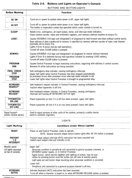
OPERATOR'S CONSOLE
The operator's console and the console typewriter are the primary media of communication between
the operator and the system. The console contains buttons and lights which the operator uses to con-trol and monitor the operation of the Central Proc-essor and the input-output units. The typewriter is used to transmit and record operator-program communications, which include program requests for operator intervention, the detection of machine malfunctions, program running time, and other log-ging information.
• INPUT-OUTPUT EQUIPMENT
The 'UNIVAC III System has 13 input-output chan-nels, through which data and control information are transferred between the input-output units and the Central Processor. Four channels-two read and two write- are allocated to the UNISERVO IlIA tape system; eight channels are general-purpose input-output channels, allocated to card-punch units, printers, and other peripheral devices; and one channel is the read-write channel for a UNISERVO IIA tape system. As many of the 13 channels as are desired may be used initially; the remaining channels then are available to meet increasing data-processing requirements.
data and to control the simultaneous operation of the peripheral devices.
Since the configuration of peripheral equipment will vary from one installation to the next, the require-ments for controlling peripheral operations also will vary. Executive monitoring systems and the input-output subroutines of the assembly systems provide the necessary flexibility to control peripherals; these software systems may be modified readily to meet the requirements of any installation.
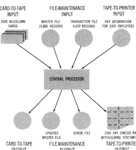
To illustrate the efficiency of concurrent on-line peripheral operations, a data-processing example is described below and illustrated in figure 1-2.
A tape-to-tape file-maintenance run operates concurrently with a tape-to-printer run and a card-to-tape conversion. The primary input to the file-maintenance run is a master file (composed of 250-word records), which is processed against a transaction file. The master file contains 19,800 records, and the transaction file contains 6600 records. The entries in both files have been pre-ordered in ascending sequence and are recorded on tape in 500-word blocks. The output of the
CARD-TO-TAPE INPUT
3500 80-COLUMN CARDS
CARD-TO-TAPE OUTPUT
FILE-MAINTENANCE INPUT
TAPE-TO-PRINTER INPUT
MASTER FILE TRANSACTION FILE PAY INFORMATION 19,800 RECORDS 6,600 RECORDS FOR 1000 EMPLOYEES
UPDATED
M_~STER FI LE
ERROR FILE
FILE-MAINTENANCE OUTPUT
1000 PAY CHECKS AND WITHHOLDING STATEMENTS
TAPE-TO-PRINTER OUTPUT
Figure 1-2. Data-Processing Example
GENERAL DESCRIPTION Input-Output Equipment
file-maintenance run is an updated master file, which is approximately the same size as the master file, and an error file, which lists erroneous transaction records for subsequent printing. While the file-maintenance run is proceeding, 1000 paychecks and withholding statements are printed from a pre-edited tape file. At the same time, the information from 3500 80-column cards is checked and converted to tape for processing in a subsequent run.
These three runs are completed in approximately five minutes. Of this, 34 seconds of central-proc-essor time is used for the tape-to-printer and card-to-tape runs. The remaining time is available for the file-maintenance run. Thus, the Central Processor controls the concurrent operation of the peripheral devices at the same time that it is pro-cessing tape data.
UNISERVO IliA TAPE SYSTEM
GENERAL DESCRIPTION Input-Output Equipment
two read operations, or a read operation and a write operation, can be performed simultaneously.
Information is recorded on tape in variable-length blocks at a density of 1333 characters (2000 digits) per inch with an interblock gap of approximately 0.6 inch; tape moves past the read-write heads at a rate of 100 inches per second. Thus, each tape-handling unit transfers 133,300 characters (200,000 digits) per second. Rewind time is 125 seconds for a 3600-foot reel of tape.
Scatter-read and gather-write functions permit tape da ta to be transferred to and from nonadjacent areas of memory under the direction of control words supplied by the program. This means that data being read from tape can be dispersed auto-matically to the areas of memory in which it will be processed by the program. During write operations, data can be transferred directly to tape from the areas of memory in which it is computed, and auto-matically assembled into blocks by the synchronizer.
All data written onto tape is automatically check-read. If an error occurs, the synchronizer marks the incorrectly written block with a bad-spot pattern and alerts the program so that the erroneous block may be rewritten. When the tape is read later, the synchronizer will automatically detect the bad-spot pattern and alert the program so that it can bypass the erroneous block. In addition to the automatic check-read, a number of other checks (described in detail in table 3-2) are made on the information transferred to and from tape, on the operation of the synchronizer, and on the operation of the individual tape-handling units. If errors are detected by any of these checks, program-testable indicators are set and the program is alerted by means of an interrupt.
As a no-cost option, the synchronizer and tape-hand-ling units may be modified so that the system can read and write tapes which are compatible with the UNIVAC 1107 Thin-Film Memory Computer and the UNIVAC 490 Real-Time System.
A second UNISERVO IlIA synchronizer may be added to the system so that up to 32 UNISERVO IlIA tape-handling units may be used. With this configuration, data is transferred between the synchronizers and the Central Processor through two read channels and two write channels, so that four read opera-tions, or two reads and two writes, can be performed simultaneously.
HIGH-SPEED READER
A UNIVAC III System may contain one or more 80-or 90-column High-Speed Readers, each of which is controlled by an individual synchronizer which transfers data and control information to and from the Central Processor through one of the eight general-purpose channels.
Each reader has a 2000-card input magazine, two read stations in which the cards are brush-sensed, and three 1000-card output stackers. Cards are fed from the input magazine under program control at a rate of 700 cards per minute and committed to continuously moving rollers which advance the cards through the two read stations. The number of holes sensed at the first read station is transferred to the synchronizer, where it is later compared with the number of holes sensed at the second read station; no data sensed at the first read station is transferred to memory. The card image from the second read sta tion is transferred to the area of memory desig-nated by the program.
If specified by the program, the card image from the second read station will be translated automatically by the synchronizer from Hollerith or Remington Rand 90-column card code* to the UNIVAC III character code as it is transferred to memory.
After a card has been sensed at both read stations and its image has been transferred to memory, it is de-posited in the output stacker designated by the program.
In addition to the hole-count check, a modulo-3 check is made on each word of the card image as it is received from the synchronizer by the Central Processor, and various other checks are made on the data sensed, on the operation of the reader, and on the operation of the synchronizer. These checks are described in detail in table 4-4. When an error occurs, program-testable indicators are set and the program is alerted by means of automatic program interrupt.
CARD-PUNCH UNIT
A UNIVAC III System may contain one or more 80-or 90-column Card-Punch Units, each of which is controlled by an individual synchronizer which transfers data and control information to and from the Central Processor through one of the eight general-purpose channels.
Each unit has a 1000-card input magazine, a punch-ing mechanism, check-read brushes, and two 1000-card output stackers. Cards are fed from the input magazine under program control at a rate of 300 cards per minute. The cards are transported by clutched rollers past the punching mechanism, which punches the data from the area of memory desig-nated by the program into the card.
If specified by the program, the data will be trans-lated automatically from UNIVAC III character code
GENERAL DESCRIPTION Input-Output Equipment
to Hollerith or Remington Rand 90-column card code before it is punched.
After the card is punched, it is moved past the check-read brushes where a hole-count check is made by the synchronizer; no data sensed by the check-read brushes is transferred to memory.
After the card has been brush-sensed, it is committed to continuously moving rollers and is deposited in the output stacker designated by the program. In addition to the check-read operation, other checks are made on the data, and on the operation of the synchronizer and punch. These checks are des-cribed in detail in table 5-4. If any error or abnormal condition is detected, program-testable indicators are set and an input-output interrupt occurs.
HIGH-SPEED PRINTER
A UNIVAC III System may contain one or more High-Speed Printers, each of which is controlled by an individual synchronizer which transfers data and control information to and from the Central Pro-cessor through one of the eight general-purpose channels.
GENERAL DESCRIPTION Input-Output Equipment
lines per inch, is controlled by the operator. The character set consists of 51 printing characters: A through Z, 0 through 9, and 15 punctuation marks and special symbols. Up to five carbon copies may be produced, using continuous sprocket-fed paper stock from 4 to 22 inches wide.
A number of automatic checks are made on the data, on the operation of the printer, and on the operation of the synchronizer. These checks are described in detail in table 6-3. If errors are detected by any of these checks, program-testable indicators are set and program interrupt occurs automatically.
CENTRAL PROCESSOR
The Central Processor controls the overall operation of the UNIVAC III System, under the direction of a stored program or programs. The programs consist of UNIVAC III words- the primary units of informa-tion with which the Central Processor operates. Following a description of the UNIVAC III word, this section presents central-processor control ele-ments and programming features, and a detailed description of each instruction in the central-pro-cessor list. Input-output instructions are described in the sections of this manual that pertain to the input-output units.
• UNIVAC III WORD
CENTRAL PROCESSOR UNIVAC III Word
transfers and arithmetic operations; these bit posi-tions contain the bits required to make the word, considered to be a 27-bit binary value, an integral multiple of 3. (Refer to Appendix A, M odulo-3
Checking.) Because the check bits are not program-accessible they are omitted from the descriptions of data and instructions in this manual.
DATA-WORD FORMATS
As shown in figure 2-1, data may be represented in the Central Processor in alphanumeric, decimal, or binary format. The sign of a data word is plus if bit position 25 is 0, and minus if bit position 25 is 1. Decimal
A decimal data word comprises six decimal digits and a sign bit. Each digit is represented by four bits and is expressed in excess-three (XS-3) binary-coded-decimal code. All binary-coded-decimal arithmetic, shift, and con-version instructions require operands in this format.
DECI MAL DATA WORD
I
s
:nl Digit 6I
Digit 5I
Digit 4I
Digit 3I
Digit 2I
Digit 1I
25 24 21 20 17 16 13 12 9. 8 5 4 1Sign ... 0 for plus, 1 for minus
Digits 1 through 6 ... 4-bit excess-three binary-coded-decimal digits
ALPHANUMERIC DATA WORD
Sign
I~I Character 4
I
Character 3I
Character 2I
Character 1 1 125 24 19 18 '31'2 7 6 11Sign ... 0 for plus, 1 for minus Characters 1 through 4 ... 6-bit alphanumeric characters
BINARY DATA WORD
Sign
i
T I 24-Bit Binary Value I!
~-24---'
Sign ... 0 for plus, 1 for minus
Figure 2-1. Data-Word Formats
Alphanumeric
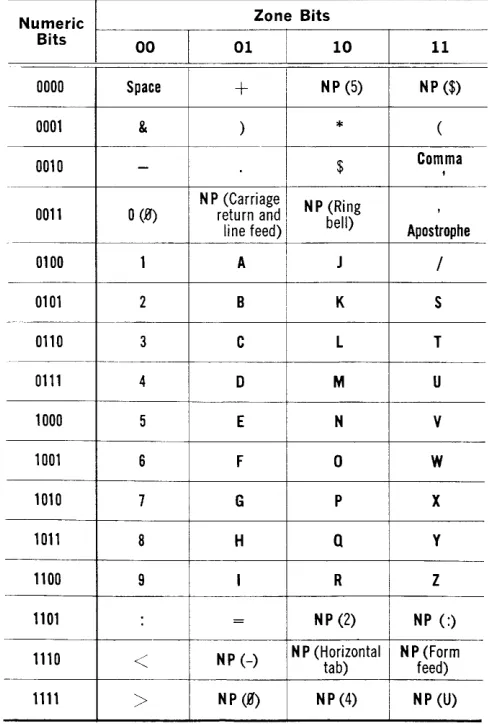
An alphanumeric data word comprises four alpha-numeric characters and a sign bit. Each character is represented by six bits: two bits for the zone, followed by four bits for the numeric portion. All alphanumeric shift and conversion instructions require operands in this format. The COBOL-FORTRAN character set for UNIVAC III Systems is shown in table 2-1. Infor-mation concerning alternate'character sets is avail-able on request.
Binary
A binary data word comprises 24 binary digits and a sign bit, expressing a value in the range plus or minus 224-1. All binary shift and arithmetic instruc-tions require operands in this format.
Table 2-1. UNIVAC III Character Code
NP indicates a code which is not printed by the High-Speed Printer. Characters and functions In parentheses pertain to the Console Typewriter only.
Numeric Zone Bits
Bits 00 01 i 10 11
I
0000 Space
+
i I NP (5) NP ($)0001 & ) * (
0010
-
$ Comma ,N P (Carriage I NP (Ring ,
0011
o
(B') return and, bell)line feed) I Apostrophe
0100 1 A
1
J /I
!
0101 2 B I K S
I
--0110 3 C L T
.e.-.
0111 4 D M U
1000 5 E N V
1001 6 F 0 W
1010 7 G P X
1011 8 H
a
y1100 9 I R Z
1101 = NP (2) NP (:)
-1110
<
NP (-) N P (Horizontal tab) NP feed) (FormCENTRAL PROCESSOR UNIVAC III Word
Table 2-2. Instruction-Word Formats
If A X
21120
Op Code Instruction
25 24
General
Shift
I ndex Register
Same for all instructions Indicator
Initiate 1-0
INSTRUCTION-WORD FORMATS
Five basic formats are used for UNIVAC III instruc-tions, in each of which the grouping of bits is the same. As shown in table 2-2, the functions of some bit groups vary with the type of instruction, while the function of other groups always is the same.
Bit Position 25: I/A-Indirect-Addressing/Field-Selection Option
Indirect addressing allows instructions to express operand addresses indirectly through intermediate control words. When it is used, the address in the instruction is that of an indirect-address (IN AD) control word which contains the actual memory address to be referenced.
Field selection allows instructions to operate directly upon fields which are not isolated within computer words. When field selection is used, the address in the instruction is that of a field-select (FSEL) control word which specifies the boundaries and address of the operand.
Both indirect addressing and field selection are specified by a 1 in bit position 25 of the instruction word. The specific option to be used is determined by the format of the control word addressed.
Bit Positions 21 through 24:
x-Index-Register Designation
All instructions are indexed as part of the basic instruction cycle. The contents of the designated index register are added to the m portion of the instruction word, giving a 15-bit field which is designated m'. The X field contains the binary
desig-I ARfXO desig-I m
II
1514 1110
AR Operand address
AR Shift count
XO Operand address
Class
Channel Indicators Indicator
Channel Function -specification address
nation, 0001 through 1111, of one of the 15 index registers. If 0000 is specified, no effective indexing takes place and m' equals m.
The instruction word in memory and the contents of the index register are not altered by the indexing process.
Bit Positions 15 through 20: Op Code-Operation Code
The operation code is designated in the instruction word by a 6-bit binary number, 000000 through 111111. For ease of representation it is expressed in this manual as a two-digit octal number, 00 through 77.
Bit Positions 11 through 14: AR/XO
The function of this field varies with the type of instruction. It is used to designate arithmetic regis-ters, operand index regisregis-ters, indicators*, groups of indicators, and input-output channels. When it is used to designate arithmetic registers, the number of registers designated indicates the number of words in the operand.
Bit Positions 1 through 10: m
This field is always indexed, giving m', which is a 15-bit field whose function varies with the type of instruction, as indicated in table 2-2. When indirect addressing or field selection is specified, m' is the address of an IN AD or FSEL control word which, in turn, serves the original function of m'.
CENTRAL PROCESSOR
Programming Features
• PROGRAMMING FEATURES
The design of the UNIVAC III System provides a number of programming features which increase the power of each instruction, provide efficient techniques of address modification and variable addressing, and allow more efficient use of internal storage and input-output media. These features are automatic index-ing, indirect addressindex-ing, multiword operands, and field selection.
AUTOMATIC INDEXING
A UNIVAC III System contains either 9 or 15 index registers whose primary function is the modification of instruction references to memory addresses. As a part of the basic instruction cycle, the memory-address portion of the instruction word and the con ten ts of one of the index registers are added; the result is the memory address to be referenced by the instruction. The address modification requires no additional machine cycles and does not alter the base address reference in the instruction word. By altering the contents of an index register, a routine can be applied to data anywhere in memory. The routine itself may be written with only relative addresses specified so that it may be relocated in memory as operational requirements dictate. The index registers, and the instructions associated with them, also provide efficient methods for program loop control and other counting functions. By means of the index registers and the automatic indexing process, these functions and the primary function of address modification can be achieved with a mini-mum number of program steps; thus program run-ning times are reduced and the memory is used more efficien tly.
Each index register contains a 15-bit unsigned binary number. The index register to be used is specified by its binary designation, 0001 through 1111, in bit positions 21 through 24 of the instruction word. As the instruction is being set up for execution, bit positions 1 through 10 of the instruction word, usu-ally a memory address and referred to as m, and the 15-bit value in the specified index register, X, are added. The resulting 15-bit value is designated rn',
and is the effective operand address. Carries beyond bit position 15 are ignored. The instruction word and the contents of the index register are not altered. If
X is 0000, no effective indexing takes place and m' equals m.
Specifying one of the optional index registers (10 through 15) when it is not in the particular system in use will not cause an error; all binary l's will be added to m, giving m'.
INDIRECT ADDRESSING
In some programming situations it is desirable to specify the location in which the address of an oper-and or instruction is stored, rather than specifying the address directly. This method of addressing operands or instructions is called indirect addressing. I t is especially useful in table-handling functions, the manipulation of variable lines of coding, sorting and merging procedures, and other program func-tions which require flexible and efficient variable-addressing techniques. In the UNIVAC III System, indirect addressing, together with automatic index-ing, provide the means for/implementing such addres-sing techinques.
Indirect addressing (II A) is specified by placing a 1 in bit position 25 of the instruction word. The address developed from the instruction word is the location of an indirect-address (INAD) control word. The memory address to be referenced by the instruction is then developed from the INAD con-trol word. Expression of this memory address may be deferred through another level of indirect addressing by placing a 1 in bit position 25 of the INAD con-trol word; the address developed from the IN AD control word will then be the location of a second INAD control word. In this way, indirect addressing can be extended through as many levels as desired. This cascading process terminates when an INAD control word with a 0 in bit position 25 is accessed. The instruction will then be executed, using the memory address developed from the last INAD control word.
An INAD control word has the following format:
I
I~I X ! 000 IUnaSSignedl _ _ _ _ _ L._A_dd_re_S_s _ _ _ _ 1
25 24 21 20 18 17 16 15 1
II A ... Indirect-addressing lfield-selection option
X ... Binary designation of in-dex register
Bit positions 18 through 20 ... Binary O's, indicating an IN AD control word
Bit positions 16 and 17 ... Unassigned
An instruction using indirect addressing is executed in the following manner:
1. The instruction is accessed and decoded. An in-dexed address, m', is developed and bit 25 is examined.
2. If bit 25 is a 1, execution of the instruction is delayed and the control word in m' is accessed. 3. A new m' is developed from the accessed control word and bit position 25 of the control word is examined. If bit position 25 is a 1, steps 2 and 3 are repeated until a control word with a 0 in bit position 25 is accessed.
4. If bit position 25 is a 0, the control word is further examined. If bit positions 18 through 20 are binary O's, them' which has been developed from the control word is the memory address to be refer-enced by the instruction, and the instruction is then executed. (If bit positions 18 through 20 are not binary O's, the control word is a field-select con trol word.)
An additional memory cycle is added to the instruc-tion execuinstruc-tion time for each INAD control word accessed.
MULTIWORD OPERANDS AND FI ELD SELECTION
"\iVith the multiword-operand and field-selection features of the UNIVAC III System, fields in any of the three data formats, and ranging in size from one data unit (bit, digit, or character) to four words, can be processed directly with single instructions. With this facility, it is unnecessary to isolate packed fields, to align fields with computer \vol'ds, or to process each \vord of a multi\vord field separately. There-fore, input-output media and memory can be used efficien tly by packing fields wi thin words and records. In addition, the need for fewer program steps results in reduced program running times and in conserva-tion of memory.
Multiword Operands
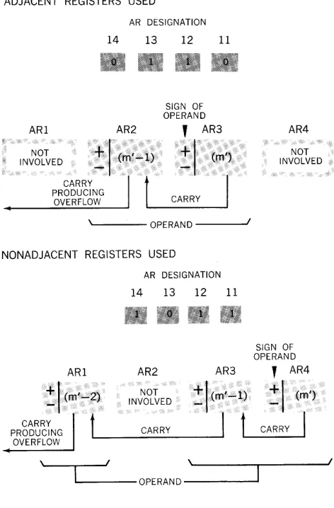
The UNIVAC III System contains four I-word arith-metic registers: ARl, AR2, AR3, and AR4. The arithmetic registers used in the execution of an instruction are designated by the bits in bit positions 11 through 14 of the instruction \vord as follows:
Register Bit Position: Designated 14 18 12 11
ARI 1 0 0 0
AR2 0 1 0 0
AR3 0 0 1 0
AR4 0 0 0 1
CENTRAL PROCESSOR Programming Features
Through combinations of these designations, oper-ands of from one to four words in length can be processed with a single instruction. The number and position of I-bits in bit positions 11 through 14 con-trol the size of the operand and its placement within the arithmetic registers. Arithmetic registers not specified will not be affected by the instruction (see figure 2-2).
Whether the arithmetic registers selected are ad-jacent or nonadad-jacent, they act as a single extended register. The words of the operand in memory, how-ever, are always in adjacent memory locations. The memory location specified by the instruction (m')
contains the least significant word of the operand, which is transferred to or from the highest numbered arithmetic register designated, or is combined or
ADJACENT REGISTERS USED
ARI
AR DESIGNATION 14
AR2
13 12
SIGN OF OPERAND
11
, AR3
NOT
INVOLVED
~I
(m'-l)~r
(m')CARRY
t
PRODUCING
OVERFLOW ... _ _ CA_R_R_Y_--J ' - - - OPERAND --~
NONADJACENT REGISTERS USED
ARI
~.I
(m' ....
2)CARRY
t
PRODUCING OVERFLOW
I
AR DESIGNATION 14 13 12 11
AR2 AR3
NOT
~I(m'-:l)
INVOLVED
CARRY
I
t
OPERAND
AR4
NOT INVOLVED
SIGN OF OPERAND
,
AR4
~I
(m/)CARRY
I
I
CENTRAL PROCESSOR
Automatic Program Interrupt
compared with the contents of that register. The balance of the operand in the lower ordered memory locations is processed similarly with the lower num-bered arithmetic registers designated.
The sign of the least significant word of a multiword operand is taken as the sign of the entire operand; the signs of the other words are ignored. Each word of the result of an arithmetic operation has the same sign as that of the least significant word.
Carries or borrows between designated arithmetic registers are allowed to propagate. Only when there is a carry or borrow beyond the most significant arithmetic register designated will the arithmetic-overflow indicator be set.
Generally, when a multiword operand is specified, an additional machine cycle for each word beyond one should be added to the basic execution time.
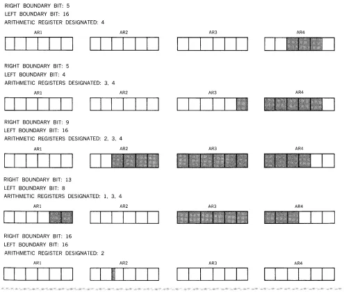
Field Selection
When a field is split across computer words or is packed in a word with other fields, field selection may be used to designate only those bits, digits, or char-acters to be manipulated (see figure 2-3). The address and boundaries of the field are defined by a field-select (FSEL) control word.
Field selection is called for by a 1 in bit position 25 of the instruction word. The effective address speci-fied by the instruction, m', is the address of the FSEL control word. The format of the FSEL con-trol word is as follows:
x
25 24 21 20
Bit 25
Left
Boundary
Bit 16115
Right
Boundary
Bit
m
1110
.... Always O. The FSEL control word may not reference an indirect-address control word.
X ... Binary designation of an index register
Left Boundary Bit .... Position of the most significant bit of the field to be selected, expressed in excess-three binary code
Right Boundary Bit ... Position of the least significant bit of the field to be selected, expressed in excess-three binary code
m ... Unindexed memory address of the least significant portion of the field
NOTES
1. The most significant bit position of a word is desig-nated 24 (11011); the least significant bit position is designated 1 (00100). The sign, bit position 25, may not be designated.
2. If the operand is multiword, the left boundary bit is in the most significant word, and the right boundary bit is in the least significant word. The arithmetic registers designated need not be adjacent, but the operand will always be selected from contiguous memory locations.
3. Sign bits are not selected, and the sign of each word of the operand is positive.
4. Portions of the words beyond the boundaries specified are treated as binary O's. In decimal add and subtract operations they are treated as decimal O's.
5. Carries and borrows are allowed to propagate up to bit position 24 of the most significant arithmetic register designated. An attempted carry or borrow beyond this bit position will set the arithmetic-overflow indicator.
6. If only one bit is to be selected, its position should be designated as the left and right boundary bits.
7. The FSEL control word may itself be indirectly addressed but does not use indirect addressing to express an operand address; therefore, bit position 25 must always be O.
8. One machine cycle is added to the instruction execu-tion time.
• AUTOMATIC PROGRAM INTERRUPT
Automatic program interrupt is a method used to signal a program in progress that special conditions have arisen in the system which require action out-side of the main processing chain. The three classes of special conditions which cause interrupt are, in ascending order of priority, Input-Output, Contin-gency, and Processor Error.
Examples of these are as follows:
Input-Output: Availability of a magnetic-tape unit for further use after successful completion of a write operation.
Contingency: A type-in by the operator.
When the conditions calling for interrupt are detected by the control circuitry, the contents of the control counter are stored in a fixed memory location asso-ciated with the particular class of interrupt. (Fixed memory locations are summarized in Appendix H.) Control is then transferred to another fixed location, the contents of which initiate a routine to determine the cause of the interrupt and to take suitable action. Following such action, the stored control-counter reading returns the program to the point at which interrupt occurred.
When a condition calling for interrupt arises, the fol-lowing action takes place wi thin the Cen tral Processor.
RIGHT BOUNDARY BIT: 5 LEFT BOUNDARY BIT: 16
ARITHMETIC REGISTER DESIGNATED: 4
ARI AR2
I I I I I I I I I I I I I I
RIGHT BOUNDARY BIT: 5 LEFT BOUNDARY BIT: 4
ARITHMETIC REGISTERS DESIGNATED: 3, 4
ARI AR2
I I I I I I I I I I I I I I
RIGHT BOUNDARY BIT: 9 LEFT BOUNDARY BIT: 16
ARITHMETIC REGISTERS DESIGNATED: 2, 3, 4
ARI
I I I I I I I
RIGHT BOUNDARY BIT: 13 LEFT BOUNDARY BIT: 8
AR2
ARITHMETIC REGISTERS DESIGNATED: 1, 3, 4
ARI
RIGHT BOUNDARY BIT: 16 LEFT BOUNDARY BIT: 16
AR2
I I
ARITHMETIC REGISTER DESIGNATED: 2
ARI AR2
I
I I I I I
I
I I
I
I
I I
I I
CENTRAL PROCESSOR Automatic Program Interrupt
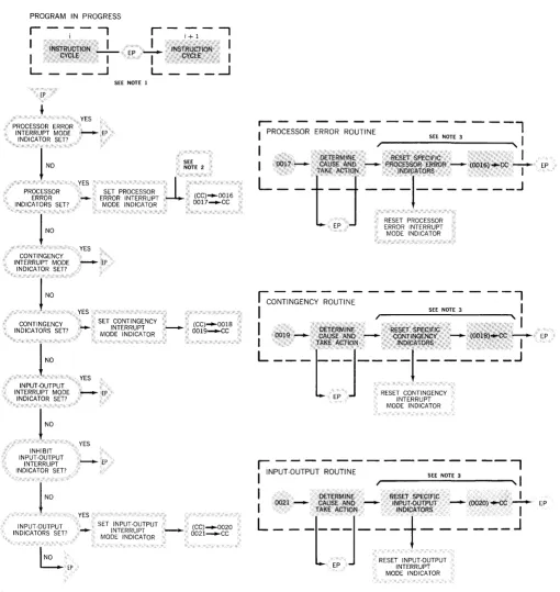
A program-testable indicator, or group of indicators, is set to identify the specific condition calling for interrupt. For each class of interrupt there is an Interrupt-Mode Indicator (IMI). These indicators are automatically set, reset, and tested by the control circuitry and are not accessible to the program. When an 1M I is set, interrupts of the same class or of classes with a lower priority are inhibited. Interrupts of a higher class, and the setting of specific indicators when interrupt conditions arise, are not inhibited. As shown in figure 2-4, at the completion of each instruction, classes of interrupt indicators are auto-matically probed in descending order of priority. If
AR3 AR4
I I I I I I
I
AR3 AR4
AR3 AR4
AR3 AR4
AR3 AR4
I
I I
I I I I I I I I
CENTRAL PROCESSOR Automatic Program Interrupt
any specific indicator is found to be set, and if the IlVII for its class or for a class of higher priority is not set, interrupt takes place. At this time the IMI for the class of interrupt occurring is automatically set in order to prevent subsequent interrupts of the same or lower classes from taking place while the current interrupt is being processed.
The control-counter reading, which is the address of the next instruction in the interrupted program, is stored in a fixed memory location associated with the class of interrupt taking place. Bit positions 1 through 15 of the memory location contain the con-trol-counter reading; bit positions 16 through 25 are cleared to binary O's. This memory location may be used later as an indirect-address (INAD) control word to return control to the interrupted program. Control is transferred to another fixed memory tion associated with the class of interrupt. The loca-tions associated with each class of interrupt are as follows:
Control-Counter Control Class of Reading Stored Transferred Interrupt m to
Processor Error 0016 0017
Contingency 0018 0019
Input-Output 0020 0021
Control is thus transferred to one of three locations where a routine to determine the exact nature of the interrupt is initiated. This determination is made by testing the specific indicators associated with the class of interrupt. When the cause of the interrupt has been identified and appropriate action taken, the specific indicators may be reset and control trans-felTed to the address specified by the stored control-counter reading. The instruction that resets the specific indicators (RPE, RCI, or RIO) automatically resets the interrupt-mode indicator for the class of interrupt involved. Interrupts of all classes are then inhibited until the instruction following the reset instruction is completed.
The processing of all interrupts and interrupt condi-tions is one of the funccondi-tions of the executive moni-toring routines, and of the input-output subroutines provided by the assembly systems. Detailed des-criptions of these routines are provided in separate manuals.
INPUT-OUTPUT INTERRUPT
At the completion of each instruction, if no processor error or contingency indicators are found to be set,
the input-output interrupt indicators are auto-matically tested as a group. If any input-output indicator is set, and no interrupt-mode indicator is set, output interrupt will occur. The input-output interrupt-mode indicator (101M!) is then set; the contents of the control counter are stored in memory location 0020; and control is transferred to memory location 002l.
When the IOIMI is set, the further setting of specific input-output indicators will not be inhibited; how-ever, a second input-output interrupt will not occur until the completion of the instruction that follows the reset input-output indicators (RIO) instruction. If any processor error or contingency conditions arise while the 101M I is set, interrupts of these classes will occur.
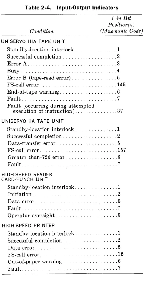
Input-output interrupt occurs when input-output interrupt indicators have been set due to one of the following conditions:
Error or fault conditions have prevented the proper execution of an input-output operation and correc-tive action, either by program steps or operator intervention, must be taken.
An input-output operation has been initiated in the High-Speed Reader or Card-Punch Unit, or has been successfully completed, in magnetic-tape units or the High-Speed Printer. Interrupt upon initiation occurs when a function specification has been accessed from the standby location of the channel by the synchronizer for the input-output device; interrupt upon successful completion can occur only when an input-output operation has been completed, and no error or fault indicators have been set. Interrupt upon initiation or success-ful completion indicates that the input-output synchronizer concerned is ready to accept another function specification; this interrupt occurs only if bit position 16 of the function specification con-tains a 1.
PROGRAM IN PROGRESS
r-"7--'
r -
i:-1 - --,
...!-
·:1NsfR·UQ(ON.··. I
, OYCLe .•. ,I
I .i~STRU6tI0N .•.. ,,.·,GYCll"r>-I- EP
L _ _ --1 L _ _ _
...J
EP
PROCESSOR ERROR INTERRUPT MODE
INDICATOR SET?
PROCESSOR ERROR INDICATORS SET?
CONTINGENCY YES
YES
-YES
SEE NOTE 1
SEE NOTE 2
E~~1:~~~f~~~~Tl
(CC)-0016MODE INDICATOR' . 0017 .... CC
INTERRUPT MODE - EP INDICATOR SET?
!
NOCONTINGENCY INDICATORS SET?
1
NOINPUT·OUTPUT INTERRUPT MODE
INDICATOR SET?
INHIBIT INPUT·OUTPUT
INTERRUPT INDICATOR SET?
INPUT·OUTPUT INDICATORS SET?
NOTES:
INO
L:...-
EP YESSET CONTINGENCY ... INTERRUPT
MODE INDICATOR
YES
- E P
YES
- E P
YES
SET INPUT·OUTPUT - - INTERRUPT
MODE INDICATOR
-
(CC) .... 0018 0019 ... CC(CC)~020 0021_CC
CENTRAL PROCESSOR
Automatic Program Interrupt
r-;R~ES~ ;;O;;O;I~ - - - -
- l
I
,
SEE NOTE 3,
I
I ci£rEeMINE' RtseTsf>e.bIFlc 1
lob17~ CAUSE ANO---F:ROC ERROR-- (0016) ... CC - EP
L __
tTAKE.ACTj!QN. _ _
)~!
ORS _ _ _ _ _ _
~
RESET PROCESSOR EP ERROR INTERRUPT MODE INDICATOR
SEE NOTE 3
I
---,
I
, I
r - - - ,
I
INPUT·OUTPUT ROUTINE I SEE NOTE 3,I
I
DETERMINE RESET sPECIFICI 0021 - TAKE ACTlON CAUSEAND - - - INPUT"OUTPUT INDICATORS
L - -
-t -
-j ---
i
-RESET INPUT·OUTPUT EP INTERRUPT
/ . I - - - (0020)...ce-
,
EP____ J
MODE INDICATOR
1. Operations within the dotted lines are performed by pro-gram steps. Operations outside of the dotted iines are auto-matically performed by the control circuitry. EP is performed by the control circuitry when the ending pulse is generated at the completion of each instruction (i). If interrupt does not occur, the instruction (i+1) in the location specified by the contents of the control counter is executed. If interrupt
occurs, the address of i+1 (contents of the control counter) is stored and control is transferred to the appropriate inter-rupt routine.
2. If further processor errors occur after the processor error interrupt mode indicator has been set, the Central Processor will stop.
3. Interrupts of all classes are inhibited during this time.
CENTRAL PROCESSOR Control Unit
CONTINGENCY INTERRUPT
At the completion of each instruction, if no processor-error indicators are found to be set, the contingency indicators are automatically tested as a group. If any contingency indicator is set, and neither the proces-sor-error interrupt-mode indicator nor the contin-gency interrupt-mode indicator (CIMI) is set, con-tingency interrupt will occur. The CIMI is then set, the contents of the control counter are stored in memory location 0018, and control is transferred to memory location 0019.
When the CIMI is set, the setting of specific con-tingency or input-output indicators will not be in-hibited; however, contingency or input-output interrupt cannot occur until the instruction that follows the reset-contingency-indicators (RCI) in-struction is completed. If any processor-error con-dition arises while the CIMI is set, a processor-error interrupt will occur.
The conditions which call for contingency interrupt are of two classes, external and internal. External contingency conditions, which are associated with the operator's console and console typewriter, facili-tate programmed operator-system communication:
Typewriter Interrupt: A character has been typed in or typed out.
Keyboard Request: The operator is requesting that the console-typewriter keyboard be acti-vated so that a message may be typed.
Keyboard Release: The operator has completed a type-in and the keyboard is de-activated. Contingency Stop: The operator has pressed
the PROGRAM STOP button, requesting that the program bring the system to a halt.
Internal contingency conditions are as follows: Arithmetic Overflow: An add or subtract
oper-ation has resulted in a carry beyond the most significant arithmetic register designated, or a divide operation has been attempted in which the absolute value of the divisor is not greater than the absolute value of the dividend.
Clock Power Disrupted: The addressable clock has been accessed (LT instruction) while in a non-ready condition due to a previous removal of clock power.
Invalid Op Code: The execution of an instruction whose operation code is not in the repertoire for the system has been attempted.
PROCESSOR-ERROR INTERRUPT
At the completion of every instruction, the processor-error indicators are automatically tested as a group. If any indicator is set, and the processor-error inter-rupt-mode (PEIMI) indicator is not set, interrupt will occur. The PEIMI is then set, the control-counter reading is stored in memory location 0016, and control is transferred to memory location 0017. If further processor errors occur after the PEIMI has been set, the Central Processor will stop.
When the PEIMI is set, the setting of specific con-tingency and input-output indicators will not be in-hibited. However, interrupts of these classes cannot occur until the instruction that follows the reset-processor-errors (RPE) instruction has been com-pleted.
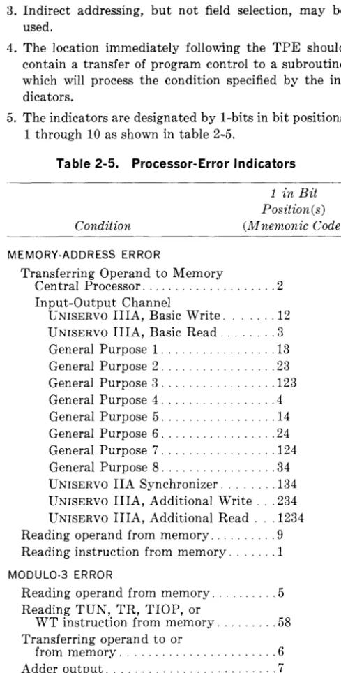
There are two types of processor errors: address errors and modulo-3 errors. A memory-address error indicator is set when the memory location accessed is not that which was addressed, or when a location in a memory module not included in the particular system in use is addressed.
A modulo-3 error indicator is set when a word being accessed does not have the correct modulo-3 check bits (bit positions 26 and 27), or if the results of certain instructions in the adder fail to pass the modulo-3 check. (Refer to Appendix A, M odulo-3 Checking.) Attempting to access a location in a memory module not included in the particular system in use will also set a modulo-3 error indicator.
• CONTROL UNIT
This section describes the main functions of those components of the control unit which are involved in the execution of instructions. The execution cycles of a single-word operand instruction, a multiword-operand instruction, and an instruction using field selection or indirect addressing, are also described.
CENTRAL·PROCESSOR REGISTER
MEMORY-ADDRESS ADDER
The memory-address adder, which is separate from the arithmetic adder, is used by the control circuitry to compute the memory addresses needed to trans-fer information between memory, the Central Pro-cessor, and the input-output synchronizers. The adder is also used as a data-transfer path during the execution of certain instructions.
STORAGE-ADDRESS UNIT
The storage-address unit consists of several registers which supply addressing information for central-processor and input-output operations; these regis-ters are described in the following paragraphs.
Index Registers (X)
The 9 or 15 index registers in the system are used primarily to modify instruction references to memory addresses. The index registers and the indexing process are described in detail under the heading A utomatic Indexing.
Control Cou nter (CC)
This register is used by the control circuitry to sequence instructions. It contains a 15-bit value which is the address of the instruction being execu-ted. During the final execution phase of the instruc-tion, the contents of the control counter are normally incremented by 1 in the memory-address adder to give the address of the next instruction. Certain instructions will cause the address in the control counter to be incremented by 2 or to be replaced with a new address from the instruction word.
Memory-Address Register (MAR)
The memory-address register contains the address of the memory location to or from which information is to be transferred.
Memory-Address Counters (MAC)
Each input-output synchronizer has an associated 15-bit MAC which contains the memory-address information required by the synchronizer to perform input-output operations.
Tape Control-Word Registers (TCWR)
A one-word TCWR, which holds the tape control words used in scatter-read and gather-write (SCAT) operations, is associated with each UNISERVO IlIA channel.
CENTRAL PROCESSOR
Control Unit
INDICATOR UNIT
The indicator unit contains the program-testable indicators described below. When the indicator tested is found to be reset, the next instruction in sequence is accessed. When the indicator tested is found to be set, control is transferred to the address specified by the instruction.
Sense Indicators 1 through 8
Each of the sense indicators, which may be used for program control, may be tested, set, or reset by the program.
Inhihit-Input-Output-Interrupt Indicator
This indicator may be set, reset, or tested by the program. When it is set, input-output interrupt is inhibited; however, the setting of specific input-output indicators is not inhibited.
Comparison Indicators
The three comparison indicators, high, low, and equal, are set on the basis of comparisons of operands in the arithmetic or index registers with operands in memory. The equal indicator is also set and reset by add and subtract instructions. If the result of an addition or subtraction is zero, the equal indicator is set. If the result is not zero, the equal indicator is reset.
Arithmetic-Register-Sign Indicators
These indicators, one for the sign of the contents of each arithmetic register, may be tested by the pro-gram. The sign indicator is set when the contents of the arithmetic register are positive, and reset when the contents of the arithmetic register are negative.
EXECUTION CYCLE WITH SINGLE-WORD OPERAND
During the final execution phase of an instruction, the instruction address is transferred from the con-trol counter to the memory-address adder. Depending on the type of instruction and its result, the address in the memory-address adder is incremented by 1, incremented by 2, or replaced by a new address from the instruction word. The value thus developed, which is the address of the next instruction to be executed, is transferred to the control counter and the memory-address register.
CENTRAL PROCESSOR
Control Unit
X and AR fields of the instruction word are inter-preted to select the index register and arithmetic register to be used in executing the instruction. In the next phase of the instruction cycle, the con-tents of the selected index register and the m field of the instruction word are added in the memory-address adder; the result is m', the 15-bit memory address to be referenced by the instruction. As m' is being developed, the op-code field generates the function signals necessary to execute the instruction. The m' value is transferred to the memory-address register. If the instruction is a register-to-memory transfer, the contents of the selected arithmetic register are transferred to the location specified by the memory-address register. If the instruction requires an operand from memory, the contents of the location specified by the memory-address register are trans-ferred through the central-processor register to the arithmetic unit where they are processed. At the same time, the address of the next instruction is being computed from the contents of the control counter.
EXECUTION CYCLE WITH MULTIWORD OPERAND
If the operand is multiword, the cycle described above is executed for the least significant word of the operand, which is in either m' or the highest desig-nated arithmetic register. However, development of the next instruction address is deferred until the most significant word of the operand is being trans-ferred to or from memory.
While the least significant word of the operand is being processed, the m' address in the address register is decremented by 1 in the memory-address adder, and the result is returned to the memory-address register. The value thus developed is the address of the next operand word.
If the instruction is a register-to-memory transfer, the contents of the next lower designated arithmetic register are transferred to the location specified by the memory-address register. Otherwise, the contents of the location specified by the memory-address register are transferred through the central-processor regis-ter to the arithmetic unit, where they are processed with the contents of the next lower designated arith-metic register.
This process is repeated until the last word of the oper-and is being transferred to or from memory. At this time, the address of the next instruction is computed.
EXECUTION CYCLE WITH FI ELD SELECTION AND INDIRECT ADDRESSING
After the instruction word has been accessed from memory, but before m' has been developed, bit position 25 of the instruction word is examined. If it contains a O-bit, m' is an operand address; if it contains a I-bit, m' is the address of a field-select (FSEL) control word or an indirect-address (INAD) control word. The control word is transferred from memory to the central-processor register and its X
field is interpreted to select the index register to be used.
Bit position 25 of the control word then is examined. If it contains a I-bit, the control word is an INAD and the next word to be accessed is a control word which must in turn be analyzed. If bit position 25 contains a O-bit, bit positions 18 through 20 of the control word are examined. If they do not contain all O-bits, the control word is a FSEL and the next word to be accessed is an operand on which field selection will be performed as it is transferred to the arithmetic unit. If bit positions 18 through 20 con-tain all O-bits, the control word is an INAD and the next word to be accessed is an operand.
The address portion of the control word in the central-processor register and the contents of the selected index register are now added in the memory-address adder, to produce m', the address of the next word to be accessed.
If field selection was specified, the contents of m' are transferred through the central-processor register to the arithmetic unit, the portions of the operand outside the boundaries designated by the control word being replaced with binary O's.
If the original control word was an INAD calling for another control word, the contents of m' are analyzed and a new m' is developed. This process is repeated until a control word with a 0 in bit position 25 is accessed and the operand address can be developed.
If the control word was an INAD with a 0 in bit position 25, m' is an operand address. If the instruc-tion is a register-to-memory transfer, the contents of the selected arithmetic register are transferred to the memory location specified by m'. If the instruc-tion requires an operand from memory, the contents of m' are transferred through the central-processor register to the arithmetic unit.
CENTRAL PROCESSOR UNIVAC III Instruction List
UNIVAC III INSTRUCTION LIST
The instruction list of the UNIVAC III System is arranged in the following pages by functional category. Each category is introduced by a brief description of the general characteristics of the
instruc-tions in that category.
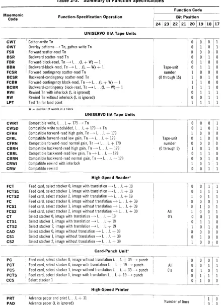
The function specifications associated with each input-output device are listed in table 2-3 (page 2-30). For a detailed description of each function specification, refer to the section of this manual that des-cribes the associated input-output device.
INSTRUCTION-LIST FORMAT
Each instruction is described in accordance with the following format:
FUNCTION-Mnemonic Code
Operation: Symbolic representation of instruction des-cription
Op Code: Operation code, expressed as two octal digits Cycles: Basic execution time, expressed in
4-micro-second memory cycles
Description: Definition of function of the instruction
1-;;1-24--211-20----151-14--111-10---11
Instruction f