--
WY-370
Programmer's
TRADEMARKS
copyrighted by Wyse Technology Inc. You may not reproduce, transmit, transcribe, store in a retrieval system, or translate into any language or computer language, in any form or by any means, electronic, mechanical, magnetic, optical, chemical, manual, or otherwise, any part of this publication without the express written permission of Wyse Technology Inc.
WYSE is a registered trademark of Wyse Technology Inc. WY-350 and WY -370 are trademarks of Wyse Technology Inc.
ADDS Viewpoint A2 is a trademark of Applied Digital Data Systems, Inc.
DEC is a registered trademark of Digital Equipment Corporation. VT52, VT100, VT220, and VT320 are trademarks of Digital Equipment Corporation.
Esprit III is a trademark of Esprit Systems Inc.
HP 18-C is a trademark of Hewlett-Packard Corporation.
Intecolor and ColorTrend 220 are trademarks of Intecolor Corporation.
IBM is a registered trademark of International Business Machines Corporation. IBM Enhanced PC, and IBM Pro Printer are trademarks of International Business Machines Corporation.
Microsoft Serial Mouse is a trademark of Microsoft Corporation.
Tektronix and TEK are registered trademarks of Tektronix, Inc.
TeleVideo is a registered trademark of TeleVideo Systems, Inc. TeleVideo 950 is a trademark of TeleVideo Systems, Inc.
DISCLAIMER Wyse Technology Inc. makes no representations or warranties regarding the contents of this document. We reserve the right to revise this document or make changes in the specifications of the product described within it at any time without notice and without obligation to notify any person of such revision or change.
RESTRICTED RIGHTS LEGEND Use, duplication, or disclosure by the Government is subject to restrictions as set forth in subparagraph (c)(l)(ii) of the Rights in Technical Data and Computer Software clause at 252.277-7013.
WYSE TECHNOLOGY INC. 3471 North First Street
WHAT YOU'LL FIND IN THIS GUIDE
This guide provides the information you need to take advantage of the terminal's programmable features. How you control the terminal will depend on your host and programming language. Refer to your language manual for details on coding terminal commands.
This guide supplements the WY-370 User's Guide, which contains the basic information necessary to install, set up, and operate the terminal.
Chapters 1 through 10 describe the commands supported by the terminal in the native (Wyse 370) and other ANSI personalities. Command descriptions assume basic familiarity with ANSI
terminal programming concepts. The guide is organized as follows: • Chapter 1 introduces terminal features and programming
procedures.
• Chapter 2 describes the commands that set and reset the terminal's functional modes, select terminal personalities, and control miscellaneous terminal processing.
• Chapter 3 explains function key programming and numeric keypad functions.
• Chapter 4 discusses how to display predefined character sets and how to design and load softfonts.
• Chapter 5 describes the commands that control the screen display, including a detailed discussion of how to combine colors and display attributes.
• Chapter 6 discusses the commands that divide display memory into pages, split the screen, and address the cursor in multiple pages.
• Chapter 7 describes standard cursor movement commands. • Chapter 8 describes the editing commands that insert, delete, or
CONVENTIONS AND SYNTAX NOTATION
Key Functions
• Chapter 9 discusses the commands that control the sending of data to the host and to the printer and other auxiliary devices. • Chapter 10 explains terminal status report requests and
responses.
The commands in Chapters 1 through 10 are summarized under functional categories in Appendix F, "ANSI Command Summary." A "Quick Reference Guide" (Appendix J) lists the same commands in ASCn order. Finally, a "Command Index" lists these commands alphabetically by mnemonic and references the page where the main discussion of each command can be found.
Appendix G, "Programming in -Wyse 3S0 Personality," describes the commands supported by the terminal in Wyse 350 personality and summarizes those supported in other.ASCn personalities.
Appendix H summarizes the commands supported in TEK
4010/4014 graphics personality.
The remaining appendixes provide technical reference material, including character sets, ASCU code conversions, key codes, local keyboard commands, and summaries of the control codes
supported by the terminal.
The term personality refers to a combination of operating
characteristics typical of a particular terminal command set (e.g.,
VT3201JlT220 personality).
Hexadecimal values are indicated by the letter H. For example, 63H is 63 hexadecimal (0110 0011 binary).
The names of keys are represented by boxed symbols or letters, for example,
1
RelumI.
Key functions described in the text are presentedas follows:
• The symbol for the key on the lOS-key ANSI keyboard is shown first, followed by key symbols in parentheses that are different for the other keyboards. For example, @]
(I
S8IupI, 1
select1
)
105-Key ANSI Keyboard
Shift
Ctr)
f!~
[It
Command Sequences
~
r.t!~.~!II!~t!'!I!"lI1j.~a~!II!~.'I'I:.~!II!~lI!~.~l!la~ • • a W • • • • 1II!11!1S1II • • • • 1S1II" • • • • • • • 1II • • 1t • • 1II • • • 1II • • all • • _ • • • • • lIIlIE8B • • 8B . . . 8BlIIllE8B 1III8UBlII!II!8B1II1II1I1II1II • • II!II! .11 • • . . alll.allllll.1II
ASCII Keyboard Enhanced PC-Style Keyboard
• When a key symbol in the text refers to one of two names on a key on the keyboard, the action of another key may be implied. For example, on the ASCII keyboard, ~ is the upper name on the key that is also marked' Send
I.
When~ appears in the text, it indicates the key pressed simultaneously with' ShiftI;
whenI
Send1
appears in the text, it means the same key by itself (unshifted). Or, on the Enhanced PC-style keyboard I Bleak 1 appears on the front face of the key that is also marked1
PauseI.
On this keyboard, the keyfunctions named I Break 1 and' Sys Rq 1 are activated when @D is pressed simultaneously with that key. Therefore, when' Break 1 appears in the text, it means the key pressed together with @D;
when I Pause 1 appears in the text, it means the same key by itself. • When necessary, an italic notation follows the key name to
identify a specific location on the keyboard. For example, @cpd
identifies the number key on the numeric keypad at the right side of the keyboard, and ~eft identifies the ~ key on the left side of the Enhanced PC-style keyboard.
Unless otherwise noted, the commands described in this guide can be entered from the keyboard as well as coded into your program.
Control codes are shown with the notation CfRL indicating the
1 CTRL 1 key.
Command sequences appear in the text with a space between each character to make the command easier to read. Don't enter the spaces in your program statements. A space character that is part of a command sequence is explicitly shown, for example,
ESC SPACE
Commands are presented in the text with a mnemonic reference followed by a brief description and the command sequence.
beginning with DEC are Digital Equipment Corporation private mnemonics; all others are ANSI mnemonics.
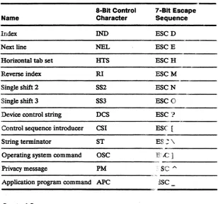
Command sequences are given in 8-bit format. Whenever an 8-bit control character is shown in the command line-for example, the control sequence introducer CSI-an equivalent 7-bit escape sequence can be used. (Equivalent 7-bit escape sequences are listed in Table 1-1 in Chapter 1.)
Overview
-"-
-~--~
What You'll Find in this Guide ... . . .. i Conventions and Syntax Notation ... :-;-'".-.-;-; .. - .
ii---Key Functions. . . .. ii Command Sequences ... :~:-.. -: .
-:-;-fij-
~~-1 Introduction
Terminal F=eatures .... -:-: ... : .. ". :-. 1-1 Operating Modes ...•...•. ,, ____ 1-2 Personalities ... .-. 1-2 Display Features .. , ..• -... -,-;"~-.-; 1-3 Keyboard Features .~~.::... 1-3 Communications Modes ... ;:-.--~ ~:=::-:-. 1-4 Programming Command Sequences ... 1-5 Control Characters . -~ . . . .. . . .. 1-6 Multiple-Character Control Functions. . . .. . . .. . . .. 1-7
2 Controlling Functional Modes and Terminal
Processing
Introduction ... 2-1 Setting and Resetting Functional Modes . . . ... . . .. 2-1 Selecting Terminal Personalities ... ~ . . . .. 2-10 Setting the Date And nme . . . .. 2-11 Controlling Terminal Processing ... 2-11 Resetting the Terminal ... 2-12 Testing the Terminal ... 2-14
3 Controlling the Keyboard
Examples of DECUDK Device Control Strings ... 0. . . . .. 3-3
Numeric Keypad Functions . . . .. 3-4 Selecting Numeric Keypad Modes ... 3-4 Related Functional Mode Commands ... " 3-5
4 Defining and Displaying Character Sets
Introduction ... 4-1 Displaying Character Sets. . . .. 4-1 Selecting a User-Preferred Supplemental Character Set 4-3 Labeling Character Sets . . . .. 4-3 Assigning Font Banks . . . .. 4-5 Examples .•... 4-5 Creating and Loading Softfonts ... " 4-5 Overview. . . . • . . . .. 4-5 Designing and Encoding the Softfont Character .. . . . .. 4-6 Loading a Softfont . . . .. 4-15 Displaying the Softfont Characters ... 4-18 The WYLSFNT Softfont Load Command ... 4-18 Designing the Softfont Character. . . .. 4-22 Encoding the Soflfont Character ... 4-22 Loading the Character ... 4-25 Related Functional Mode Commands. . . .. 4-25
5 Controlling the Screen Display
Effect of Basic SGR Command in Color Map Mode .... 5-21 Restoring Colors and Attribute Definitions .. . . .. 5-22 Color Extended SGR MODE ... 5-22 Examples in Color Extended SGR Mode ... 5-23 Color Direct Mode . . . .. 5-24 Examples of Color Direct Mode Commands ... 5-24 Effect of the SGR Command in Color Direct Mode ... 5-24 Color Index Mode ... . . .. 5-25 Establishing the Color Index ... 5-26 Selecting Colors in Color Index Mode ... 5-26 Effect of the SGR Command in Color Index Mode. . . . .. 5-27 Mode-Independent Color Commands ... 5-27 Selecting the Border Color . . . .. 5-27 Selecting the Cursor Color . . . .. 5-28 Selecting the Top Status Line Colors ... 5-28 Selecting Replacement and Nonerasable Character
Attributes and Colors ... 5-28 Defining Line Attributes .. . . .. 5-29 Related Functional Mode Commands. . . .. 5-30
6 Controlling Display Memory
Introduction ... 6-1 Screen and Page Display. . . .. 6-1 Sessions . . . .. 6-2 Controlling Pages and Windows ... 6-3 Defining Pages ... 6-4 ContrOlling the Windows ... 6-7 Addressing the Cursor in Multiple Pages. . . .. 6-8 Panning ... 6-1 0
Effect of Setup Parameters . . . .. 6-12 Example of Panning Defaults . . . .. 6-13 Related Functional Mode Commands. . . .. 6-15
7 Controlling the Cursor
Cursor Movement Commands . . . .. 7-1 Related Functional Mode Commands ... 7-4
8 Editing
Inserting ... 8-3 Deleting ... 8-4 Controlling Tabs ... 8-4 Drawing or Clearing a Box ... 8-5 Related Functional Mode Commands ... 8-7
9 Sending Data
Introduction ... 9-1 Transmission to the Host or Auxiliary Port ... " 9-1 Suspending and Resuming Transmission ... 9-3 Sending the Answerback Message ... " 9-3 Embedded Commands and Characters Sent to Printer . 9-3 Related Functional Mode Commands. . . .. 9-6
10 Reports
Introduction ... 1 0-1 Device Attributes. . . .. 10-1 Device Status Reports ... . . .. 10-2 Terminal State Report ... " 10-3 Cursor and Tab Stop Reports . . . .. 10-4 Cursor Information Report ... 10-5 Tab Stop Report . . . .. 10-8 Control Function Reports ... 10-9 Functional Mode Reports ... 10-11
A ANSI Character Sets
National Replacement Character Sets ... A-3 Controls Display Mode ... A-8
B ASCII Code Conversion Listing
C Local Keyboard Commands
D KeyCodes
E Control Codes
G Programming in Wyse 350 Personality
Introduction ... G-1 Selecting a Personality ... G-2 Communicating with the Computer. . . .. G-2 Controlling the Terminal and Keyboard ... G-3 ContrOlling Display Features ... G-5 Protecting Data ... G-8 Assigning Display Attributes and Colors ... G-10 Displaying Graphics Characters ... G-19 Controlling the Cursor ... . . . .. G-20 Editing . . . .. . . . .. G-22 Sending Data in Block Mode ... G-24 Printing Data . . . .. G-25 ASCII Command Summary ... . . . .. G-26 National Replacement Characters. . . .. G-44
H TEK4010/4014 Command Summary
TEK 4010/4014 Personality Commands . ... H-1
Termcap
J
Quick Reference Guide
Command Index
Index
List of Figures
1-1 Communication Modes. . . .. 1-5 4-1 Labeling Character Sets and Assigning
4-6 Font Banks . . . .. 4-20 4-7 Converting the Nibbles to ASCII Values ... 4-23 5-1 Screen Areas ... 5-2 5-2 The Structure of the Color Map ... 5-11 5-3 Selecting the Foreground Color Palette ... 5-15
5-4 Selecting a Background Color . . . .. 5-17 5-5 Redefining Bold, Underline, Blink . . . .. 5-20 6-1 Default Screen and Page Configuration ... 6-2 6-2 Horizontal and Vertical Panning. . . .. 6-11 6-3 Panning Defaults . . . .. 6-14 8-1 Drawing and Clearing aBox ... 8-6 0-1 105-Key ANSI Keyboard ... , 0-1 0-2 ASCII Keyboard ... , 0-3 0-3 Enhanced PC-Style Keyboard ... 0-5 G-1 Screen Areas ... G-5 G-2 Split Screen Format. . . .. G-7 G-3 Message Fields . . . .. G-11 H-1 Screen Coordinates (X, y) ... H-6
List of Tables
1-1 8-Bit Control Characters with 7-Bit Equivalents .... 1-8 2-1 Parameter Values for SM and RM Commands .... , 2-2 2-2 Set/Reset Functional Modes ... 2-4 3-1 Key Codes ... 3-2 4-1 Default Character Sets ... 4-3 4-2 Cell Sizes. " ... 4-7 4-3 Maximum Matrix Sizes ... 4-7 4-4 Maximum Width of Text Characters . . . .. 4-9 4-5 Conversion Table (Bit Pattern Values to
ASCII Characters) ... 4-13 4-6 Conversion of Sixel Bit Pattems to
ASCII Characters ... , 4-14 4-7 Conversion Table for Binary to ASCII Values .... .. 4-24 4-8 Total Nibble Values .... . . .. 4-24 5-1 User Status Line Messages ... . . .. 5-2 5-2 System Status Line Messages. . . .. 5-3 5-3 Command Differences (Data Written
5-5 Color Modes ... 5-10 5-6 Foreground Color Palettes .. . . .. 5-13 5-7 ColorTable ... 5-16 5-8 The Attribute Associations ... . .. 5-18 5-9 Associated Attribute Values . . . .. 5-19 5-10 SGR Extended Color Values. . . .. 5-22 5-11 OefauH Color Index '" . . . .. 5-25 6-1 Local Keyboard Commands ... 6-3 6-2 Total Unes in Page ... 6-5 6-3 Page Configuration Values . . . .. 6-6 6-4 Panning Commands ... 6-12 9-1 Transmission Functions ... 9-1 9-2 Embedded Commands Summary ... 9-4 9-3 Character Attributes Sent to Printer . . . .. 9-5 9-4 Une Attributes Sentto Printer. . . .. 9-5 10-1 Primary Device Attribute Responses ... 10-1 10-2 OSR Requests and Terminal Responses ... 10-2 B-1 ASCII Code Conversion Usting ... B-1 C-1 Native Personality Local Keyboard Commands ... C-1 C-2 Local Keyboard Commands Supported in ASCII
Personalities ... C-3 C-3 Color Palette Commands (ASCII Personalities) .... C-4 C-4 Local Keyboard Commands Supported in
TEK 4010/4014 Personality ... C-5 0-1 Editing and Special Key Codes -1 05-Key
ANSI Keyboard ... 0-2 0-2 Editing and Special Key Codes - ASCII Keyboard 0-4 0-3 Editing and Special Key Codes - Enhanced
PC-Style Keyboard ... 0-6 0-4 PF-Key Codes ... 0-8 0-5 Numeric Keypad Application Mode Codes ... 0-8 0-6 Cursor Key Application Mode Codes ... , 0-9 0-7 Function Key Default Codes-105-Key ANSI
Keyboard ... 0-9 0-8 Function Key Default Codes - ASCII Keyboard .... 0-10 0-9 Function Key Default Codes - Enhanced PC-Style
F-2 VT52 Personality Escape Sequences . . . .. F-24 G-1 Function Key Label Sizes ... " G-6 G-2 Display Attribute/Color Commands ... G-10 G-3 Display Attributes ... G-12 G-4 Foreground Color Palettes " . . . .. G-14 G-5 Color Table ... " G-18 G-6 Commands Supported in ASCII Personalities ... G-28 G-7 Variable Values for Wyse 350 Commands ... G-34 G-8 National Replacement Characters:
TERMINAL FEATURES This chapter describes the main features of the terminal, discusses its operating modes and available personalities, and introduces the command sequences that determine how it displays and processes data.
This flex:tble, high-performance alphanumeric and graphics color terminal sets new standards in terminal design for user
productivity. Some of these design features are
• Modular architecture
• Dual-session capability for running two applications simultaneously
• High-resolution 16x20 character cell for 128Ox520 text resolution
• 64 independently selectable foreground and background colors and user-selectable character attributes
• Three pages of display memory (up to four pages per session with memory expansion) and 26- or 52-line by 80-, 132-, or 161-column display
• Pulldown setup menus with real-time help messages
• Integrated desktop accessories, including a business calculator (modeled after the HP-18C Business Consultant calCUlator), calendar, and alarm clock
• Multiple keyboard selections
The terminal is available in two models:
• A North American model with English, French Canadian, and Latin American keyboard language support
Operating Modes
Personalities
The terminal has four operating modes: setup, on-line, local, and WyseWorks.
• Setup mode, selectable only from the keyboard (@],
I
SetupI,
I
SeIecII ),
allows you to configure the terminal's operatingparameters, redefme colors and display attributes, set tab stops, define an answerback message, and redefine many keys on your keyboard.
• On-line mode, selectable in setup mode (On-Line/Local parameter), allows the terminal to communicate with the host. • Local mode, selectable in setup mode (On-Line/Local setup
parameter), allows you to exPeriment with the terminal's
operating characteristics without physically disconnecting it from the host system. In local mode, data from the keyboard is sent only to the terminal, not to the host. Data coming from the host
is ignored.
• WyseWorks mode, selectable from the keyboard (~ ~ ~
I
SetupI,
~I
SelectI ),
allows you to use the terminal'sdesktop accessories: a business calculator, a datebook calendar, and an alarm clock. See the WY-370 User's Guide for a
description of WyseWorks mode.
The terminal can operate in a number of different personalities, selectable in setup mode, to allow for smooth interaction with application programs written for typical terminal command sets.
ANSI Personalities
The default personality, Wyse 370, is compatible with American National Standards Institute (ANSI) command functions. It is called the native personality because it embodies the set of ANSI-based functions for which the terminal was designed. The native personality is compatible with applications written for many ANSI terminals, including the DEC VT320 and VT220 and
compatible terminals.
Other ANSI-compatible personalities are
• VT3201VT220 and VT100 for applications written for the corresponding DEC (Digital Equipment Corporation) and DEC-compatible terminals
Display Features
Keyboard Features
The VTS2 personality-is for use witlr'applicatioii programs written for the DEC VI'S2ileriIiinal.
Graphics Personality
The TEK 4010/4014 personalitY is aesigned to support Tektronix-compatible vector graphics applications.
ASCII PersonaDUes
The terminal ~t~s accordjn.i..to ASCn-bas~d_(American
Standard Code lOr Information Interchange) command functions when an ASCU personality is selected in setup mode. The
following are the terminal's ASCII personalities and the terminals they represent-__ -_-...:..:.
• Wyse 350 (WY -3SO color terminal) • 1VI 950 (TeleVldeo 950 terminal) • Esprit
m(Eijiii
ill color terminal) • ADDS A2 (ADDS Viewpoint A2 terminal)-.
'Thrminal display features"include
• 16x16 character-celJ.\?4 Hz) and 16x20 character cell (60 Hz)
• 64 independently selectable foreground and background colors and user-selectable character display attributes
• Line attnbutes, which allow you to display characters twice as wide, twice as high, or twice as wide and twice as high as normal characters
• Pulldown setup menus with real-time help messages
• Screen display with 24, 25, SO, or 51 data lines and SO, 132, or 161 columns
The keyboards supported by the terminal can be generally descnbed as having four key groups.
Main Keypad
Communications Modes
Editing Keypad
The editing keypad includes the cursor (arrow) keys and special editing keys. The codes sent by these keys depend on the terminal's current personality (see Appendix D).
Numeric Keypad
The numeric keypad contains numeric and arithmetic symbol keys and some special keys. The codes sent by these keys depend on the terminal's current personality (see Appendix D).
User-Definable Keys
The number and location of the function keys
(S
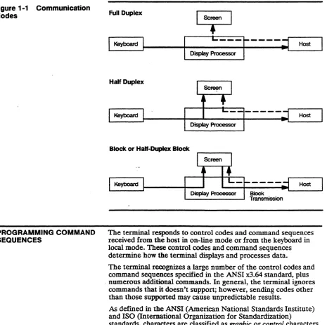
~, etc.) depend on your keyboard. Most of these keys and many editing keys are user-definable in setup mode or with a command sequence (see Chapter 3 and Appendix G). If the keys haven't been redefined, they send the default codes listed in Appendix D.In on-line mode, the terminal communicates with the host according to the setting of the Communications Mode setup parameter (port setup menu). Four modes of communication are possible between the terminal and the host: full duplex, half duplex, block. and half-duplex block. Figure 1-1 illustrates the flow of data in these modes.
In full-duplex mode, data sent by the terminal is not displayed on the screen unless the host echoes it. In practice, most application programs do instruct the host to echo the data to the screen for the user to monitor.
In ht:zl/-duplex mode, keyboard data is sent to the screen at the same time as to the host. Half-duplex mode should not be selected unless required-characters will display twice if the host also echoes the data to the screen.
In block mode, keyboard data is sent to the terminal only and is displayed on the screen. Data can be received from the host at any time and is displayed when received.
Figure 1-1 Communication Modes
PROGRAMMING COMMAND SEQUENCES
Full Duplex
I
~---r----;j
HostDisplay Processor
Half Duplex
Display Processor
Block or Half-Duplex Block
The terminal responds to control codes and command sequences received from the host in on-line mode or from the keyboard in local mode. These control codes and command sequences determine how the terminal displays and processes data.
The terminal recognizes a large number of the control codes and command sequences specified in the ANSI x3.64 standard, plus . numerous additional commands. In general, the terminal ignores
commands that it doesn't support; however, sending codes other than those supported may cause unpredictable results.
As defined in the ANSI (American National Standards Institute) and ISO (International Organization for Standardization)
ContrOl Characters
marks, and any other characters that are normally displayed on the screen. Control characters, which are not normally displayed, are interpreted by the terminal as actions to be performed-for example, the CR control character causes the terminal to execute a carriage return.
o
Note In controls display mode, the terminal displays symbolic representations of control characters instead of acting on them. This is useful for debugging programs.The terminal's graphic and control characters are arranged into character sets, which are illustrated in Appendix A in the form of code tables that show the decimal and hexadecimal code for each character.
Two basic sets of control characters are recognized by the terminal: • 7-bit control characters, designated as CO (the eighth bit always
0, only seven bits defining the character)
• 8-bit control characters, designated as Cl (the eighth bit always 1, all eight bits defining the character)
CO Control Characters
The terminal recognizes the CO control characters in all terminal personalities and data transmission modes.
Table E-l in Appendix E lists all the ANSI CO control characters . and identifies the actions of those supported by the terminal. CO control characters can be generated from the keyboard by holding down the CTRL key while simultaneously pressing the
alphanumeriC key identified in Table E-l.
C1 Control Characters
The terminal recognizes the Cl control characters only in the native and VI'3201VT220 8-bit personalities and only when the DatalParity Bits setup parameter is set for 8-bit data.
Multiple-Ct, a;'acter Control Functions
Control Functions
The terminal recognizes the Cl control characters only in an 8-bit environment. However, you can select their functions indirectly in a 7-bit environment by use of 7-bit code extensions specified in the ANSI x3.64 standard and descnbed under "Escape Sequences" in the next section.
Some of the functions of the single-byte control codes listed in Tables E-l and E-2 are directly related to the terminal's processing of text (e.g., CR, HTS, IND). Others function as introducers (e.g., ESC, CSI, SS2) or string delimiters (DCS, ST) for
multiple-character command sequences that provide many more control functions.
Most of the commands descnbed in the remaining chapters in this manual are multiple-character control functions. There are three basic types:
• 7-bit escape sequences • 8-bit control sequences • Device control strings
Escape Sequences
Command sequences introduced by the CO control character ESC are called escape sequences. An escape sequence consists of one or more ASCII graphic characters preceded by the ESC control character. For example, the sequence
ESC
r
pperforms a terminal mode reset.
Escape sequences can be used in either a 7-bit or 8-bit environment.
As provided for in the ANSI standard, you can use escape
Table 1-1 8-BIt Control Characters with 7 -Bit Equivalents
8-BIt Control 7 -Bit Escape
Name Character Sequence
Index IND ESCD
Next line NEL ESCE
Horizontal tab set HTS ESCH
Reverse index RI ESCM
Single shift 2 SS2 ESCN
Single shift 3 SS3 ESC 0
Device control string DCS ESC~l
Control sequence introducer CSI ESC [
String terminator ST ES:\
Operating system command OSC E'.e]
Privacy message PM SC
"-Application program command APC :SC
Control Sequences
Control sequences are multiple-character com nand sequences introduced by the Cl control character CSI (Ct,ntrolsequence introducer). For example, the sequence
CSI5W
clears all tab stops. Control sequences often contain variable parameters indicated by Pn or Ps. Pn signifi~ i a direct numerical
value, such as the number of a line or coluJhn position on the screen. Ps signifies an action or altemativeneaning; for example, the sequence
CSI49 ;Psw
selects a background color, where Ps is a df~c,mal value that stands for a color name.
Device Control Strings
Device cOntrol strings are multiple-character command sequences introduced by the Cl control character DCS (device control string) and terminated by the Cl control character ST (string terminator). A device control sequence always includes a data string-for example, a programmable key definition or a terminal report.
INTRODUCTION
SETTING AND RESETTING FUNCnONAL MODES
SM
RM
Modes and Terminal
Processing
This chapter discusses
• Set/reset commands for functional modes • Selecting terminal personalities
• Selecting 7-or 8-bit transmission • Setting the date and time
• Processing commands • Resetting the terminal • Testing the terminal
Many specific terminal functions can be turned on (set) or off (reset) by set mode (SM) or reset mode (RM) control sequences called functional mode commands.
Functional mode commands have two versions, one with a ? character immediately following the control sequence introducer CSI and one without the? character.
Set functional modes
Reset functional modes
(1) CSI Ps; ... ; Ps h or (2) CSI ? Ps ; ... ; Ps h
(1) CSI Ps; .•. ; Ps I
or (2) CSI ? Ps ; ... ; Ps I where Ps is a parameter that selects the mode to be set or reset
h indicates set mode (SM) I indicates reset mode (RM)
Thble 2-1 lists the Ps parameter values for the two versions of the SM and RM commands.
Table 2-1 Parameter Values for SM and RM Commands
(1) Ps' Mode Mnemonic DefauH2 (2) ? Ps' Mode Mnemonic Defauft2
2 Keyboard lock KAM Off 1 Cursor key application DECCKM NVR
3 Monitor CRM NVR 2 VI'S2s DECANM NVR
4 Insert IRM Off 3 132column6 DECCOLM NVR
12 Local echo disable SRM NVR 4 Scrolling DECSClM NVR
13 Control execution disable FEAM NVR 5 Reverse screen DECSCNM NVR
16 1Iansfer termination 'ITM NVR 6 Origin DECOM Off
20 Newline l.NM NVR3 7 Autowrap DECAWM NVR
30 Display disable WYDSCM Off 8 Key autorepeat DECARM NVR
31 Status line display WYS1UNM NVR 10 Block mode DECEDM NVR
32 Screen saver WYCRI'SAVM NVR 18 Print form feed DECPFF NVR
33 Steady cursor WYSTCURM NVR 19 Print extent DECPEX NVR
34 Underline cursor WYULCURM NVR 25 Text cursor enable DECTCEM NVR
35 Width change clear WYCLRM NVR 38 TEK 4010/40147 WYTEK NVR
disable 42 National replacement DECNRCM NVR
36 Delete key redefinition WYDELKM NVR character sets
37 Nonerasable area WYGATM NVR 60 Horizontal panning9 DECHCCM NVR
transmit 61 Vertical panni!J.g9 DECVCCM NVR
38 Send full screen WYTEXM NVR 64 Page coupling9 DECPCCM NVR
40 Extra data line WYEXIDM NVR 66 Keypad application9 DECNKM NVR
42 Wyse35Q4 WYASCII NVR 67 Delete key redefinition9 DECBKM NVR
68 Keylegend9 DECKBUM NVR
80 161 column9 WY161 NVR
83 52line9 WY52 NVR
84 Erasable/nonerasable WYENAT Off
attnbute select10 85 Replacement character
color9 WYREPL Off
1. Ps values are listed in two groups: In the first group are the values for terminal modes that can be set with SM command sequence (1) or reset with RM command sequence (1); in the second group are the values for terminal modes that can be set with SM sequence (2) or reset with RM sequence (2). The latter group is shown as ? Ps to indicate that sequence (2) includes a question mark immediately following the control sequence introducer CSI. Up to 16 Ps values can be specified (separated by semicolons) in any one SM or RM command sequence.
2. Mode status when terminal is tumed on or reset. NVR (nonvolatile RAM) means that the status depends on the value last saved in battery-backed memory in setup mode.
3. Return setup parameter (Keyboard menu, Key Functions submenu). 4. Set mode (SM) only.
5. Reset mode (RM) only.
6. Command is ignored during dual-session operation with a vertically split screen. 7. Set mode (SM) only. Command is ignored if the terminal is set up for two sessions. 8. Command is ignored if Keyboard Language parameter is set to U.S.
9. Native and VT320fVI'220 personalities only.
You can specify up to 16 modes in anyone SM or RM control sequence by entering multiple parameters separated by semicolons. For example,
CSI 4; 20 ; 34 h
selects insert mode, newline mode, and an underline cursor. Entering the sequence
CSI ? 1 ; 7 ; 80 h
selects cursor key application mode, autQ.wrap mode, and a 161-column display.
Do not combine parameters listed for version (1) of the command with parameters listed for version (2). For example, the sequence
CSI 4 ; 20 ; 80 h
is invalid. To set the three modes repres~nted by these parameters, you need to enter two sequences:
,_," CSI4; 20 h.
to set insert and newline modes, and
CSI? 80h
to select 161 columns.
o
Note A question mark entered anywhere in an SM or RM sequence makes it a version (2) command.Thble 2-2 lists the functional mode commands under the follOwing functional headings: .
Screen Display and Editing Functions
Keyboard Functions
Paging Functions
Cursor Control Functions
Table 2-2 Set/Reset Functional Modes
Mnemonic Command Sequence
Screen Display and Editing Functions
DECAWM CSI? 7 h
(Autowrap)
CSI?71
DECCOLM CSI ? 3 hi
(132-column)
CSI?31
DECOM CSI ? 6 h
(Origin)
CSI?61
DECSCLM CSI ? 4 h
(Scrolling)
CSI?41
DECSCNM CSI? 5 h
[Reverse screen)
CSI?51
IRM CSI4h
:Insert/replace)
CSI41
Function
Set: Automatically wraps characters to the next line after the last position on the line is exceeded. When the cursor exceeds the last position on the last line of the screen, the display scrolls up one line at a time.
Reset Characters do not wrap. Current character at the right margin is replaced with the next received character. (Default)
Set Displays 132 columns per line if a page of 132 or 161 columns has been defined. Cursor returns to home position and screen is cleared if width change clear disable
(WYCLRM) is reset.
Reset: Displays 80 columns per line. Cursor returns to home position and screen is cleared if width change clear disable (WYCLRM) is reset. (Default)
Set: Designates the top line of the scrolling region as the first line of the active data region.
Reset: Designates the top line of the screen as the first line of the active data region, regardless of the defined scrolling region. (Default)
Set: Display scrolls at the smooth scrolling speed of 4 lines per second.
Reset: Display jump scrolls as fast as the baud rate allows. (Default)
Set: Displays background color characters on the foreground color (reverse screen)
Reset: Displays foreground color characters on the background color (normal screen). (Default)
Set: Displays each received character at the cursor position; moves cursor and all characters to right of cursor one position to the right. Data that moves past the right margin is lost (unless the Page Edit setup parameter has been set to page, in which case the data wraps to the next line).
Reset: Displays each received character at the cursor position, overwriting the current character; moves cursor one position to the right of the new character. (Default)
Table 2-2 Set/Reset Functional Modes, Continued
Mnemonic Command Sequence Function
Screen Display and Editing Functions, Continued
LNM CSI20 b Set: When a LF, FF, or VT character is received, the cursor (Newline) moves to the first column of the next line.
WY522 (52 line) WY1612 (161 column) WYCLRM (Width change clear disable) WYCRTSAVM (Screen saver)
CSI 20 1
CSI?83 b
CSI?831 CSI?80b
CSI? 80 I
CSI35 h
CSI35 I
CSI32b
CSI32 I
WYDSCM CSI 30 b
(Display disable)
CSI 30 I
2. Native and VT320tv:r220 personalities only.
When
1
Return1
(I EnterI)
is pressed, the terminal sends both a carriage return (CR) and a linefeed (LF). (Sets Received CR setup parameter to CR and Received LF, Return Key and Enter Key setup parameters to CRLF.)Reset: When an LF, FF, or VT,character is received, the cursor
,
mo'VeS to the current column of the next line.
When
I
RetumI (I
EnterI )
is pressed, the terminal sends a CRonly. The cursor returns to the first position of the current line. (Sets Received CR, Return Key, and Enter Key setup parameters to CR and Received LF setup parameter to LF.) (Default)
Set: ~Sets 52-line display. Additional memory must be installed for certain line and column combinations (see Chapter 6). Reset: Sets 24-line display. (Default)
Set: Sets 161-column display. Additional memory must be installed for certain line and column combinations (see Chapter 6).
Reset: Sets 8O-column display. (Default)
Set: Screen does not clear when number of displayed columns (80/132/161) is changed.
Reset: Screen clears when number of displayed columns (80/132/161) is changed. (Default)
Set: Turns off the display when terminal receives no data or keyboard activity for approximately 15 minutes. Pressing any key or receiving new data restores the display. (Default) Reset: Does not turn off display regardless of elapsed time since
data was received.
Set: Blanks the terminal screen.
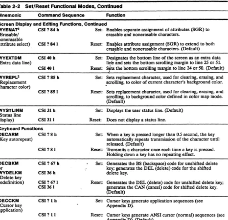
Table 2-2 Set/Reset Functional Modes, Continued
Mnemonic Command Sequence Function
Screen Display and Editing Functions, Continued
WVENAP CSI ? 84 h Set: Enables separate assignment of attributes (SGR) to (Erasable/ erasable and nonerasable characters.
nonerasable
attribute select) CSI ? 84 I
WVEXTDM CSI40h
(Extra data line)
CSI40 I
WVREPL2 CSI?8Sh
(Replacement character color)
CSI?8S1
WVSTLINM CSI31 h
(Status line
display) CSI31 I Keyboard Functions
DECARM CSI?8h
(Key autorepeat)
CSI? 81
DECBKM CSI?67h
or
WYDELKM CSI36h
(Delete key
redefinition) CSI?671 CSI361
OECCKM CSI?Ih
(Cursor key application)
CSI? 11
3. Native personality only.
Reset: Enables attribute assignment (SGR) to extend to both
eras~ble and nonerasable characters. (Default)
Set: Designates the bottom line of the screen as an extra data lir{e and sets the bottom scrolling margin to line 25 or 51. Reset: Sets the bottom scrolling margin to line 24 or 50. (Default)
,
Set: Sets replacement character, used for clearing, erasing, and
~crolling, to color of current character's background color. Reset: Sets replacement character, used for clearing, erasing, and scrolling, to background color defined in color map mode. (Default)
Set: Displays the user status line. (Default) Reset: Does not display a status line.
Set: When a key is pressed longer than 0.5 second, the key automatically repeats transmission of the character until released. (Default)
Reset: Transmits a character once each time a key is pressed. Holding down a key has no repeating effect.
Set: Generates the BS (backspace) code for unshifted delete key; generates the DEL (delete) code for the shifted delete key.
Reset: Generates the DEL (delete) code for unshifted delete key; generates the CAN (cancel) code for shifted delete key. (Default)
Set: Cursor keys generate application sequences (see Appendix D).
Table 2-2 Set/Reset Functional MOdt ',Continued
Mnemonic Command Sequence function
Keyboard Functions, Continued
DECKBUM2 eSI ? 68 h ~ t: Keys send data processing character values (when
(Key legend) available on keyboard) shown on the right legend of the key. eSI ? 68 I Rese Keys send typewriter character values (left legend). (Default)
---
DECNKM2(Keypad application)
eSI ? 66 h Se~: Numeric keypad keys send application sequences (see
DECNRCM4 (National replacement character) eSI? 661 eSI?42h eSI?421 Appendix D).
Reset: . Tumeric keypad keys send characters shown on keycap. l lefault)
Set: IT. tional mode on. Sends and receives 7-bit characters and tn \Slates them into the appropriate National Replacement C':l mcter (NRC) based on the keyboard language
chu~n.
Reset: Na:inal mode off. Displays 8-bit characters from the cane t GR set. (Default)
---
KAM CSI2h(Keyboard lock)
CSI21 Paging Functions
DECHCCM2 CSI ? 60 h (Horizontal
panning)
DECPCCM2 (page coupling)
CSI? 60 I
CSI? 64h
CSI? 641
Set: LocIc.;, 'le keyboard except for the
I
BleakI
andI
SetupI
keys. }): ;plays WAIT on the status line.Reset: Unloc.'c.··the keyboard. (Default)
Set: Display atusts to keep the cursor visible when it moves past the Ie .. or right margin. (Horizontal windowing must be turned c t in setup mode.) (Default)
Reset Cursor disal )C81"S when it moves past the left or right margin of th, display.
Set When the cur: or moves to another page, that page is displayed. (De.ault)
Reset: The page where the cursor is addressed is not displayed. Current page COl tinues to be displayed.
---
DECVCCM2(Vertical panning)
CSI? 6th
CSI? 611
Set: When the cursor. loves past the top or bottom line, the display adjusts to j, ~ep the cursor in view. (Default)
Reset: Cursor disappears \ len it moves past the top or bottom line of the display.
Table 2-2 Set/Reset Functional Modes, Continued Mnemonic Command Sequence
Cursor Control Functions DECTCEM CSI ? 25 h (Text cursor
enable) CSI ? 25 I WYSTCURM (Steady cursor) WYULCURM (Underline cursor) CSI33 h
CSI33 I
CSI34h
CSI34 I
Sending and Printing Functions DECEDM CSI ? 10 h (Block mode)
CSI? 10 I
Function
Set: Displays ~ hi; ::ursor. (Default) Reset: Does no~ 't'splay the cursor.
Set: Displa;s J steady cursor.
Reset: DispJ;::y; t blinking cursor. (Default)
Set: DisI'.?l an underline cursor. Reset: Di~,l')1'1 a block cursor. (Default)
Set: l1:lTrl' on block mode.
Reset: ".l'i.IS off block mode; puts terminal in full-duplex mode. ,uefauIt)
---
DECPEX CSI?19 h Set Prints full page. (Default) (Print
extent) CSI?191 Reset P :lnts scrolling region.
---DECPFF (print form feed) SRM (Local echo disable) TTM (Transfer termination)CSI? ISh
CSI?181
CSI12h
CSIl21
CSIl6h
CSI161
Sit ;; 'fransmits the FF (form feed] print termination character to the printer after a print page operation.
Rt::, ft; Does not transmit a print termination character to the printer after a print page operation. (Default)
3, ,t: Local echo off (full-duplex mode). Characters sent from the terminal to the host are not displayed on the screen. The host must return any characters for display to the terminal. (Default)
f :::set: Local echo on (half-duplex mode). Characters sent from the terminal to the host are simultaneously displayed on the screen.
Set: Transmits data through the cursor position in the requested transmission area. (Default)
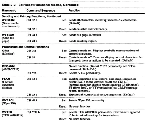
Table 2-2 Set/Reset Functional Modes, Continued
Mnemonic Command Sequence Function
Sending and Printing Functions, Continued
WYGATM CSI 37 h Set: Sends all characters, including nonerasable characters. (Default)
(Nonerasable area transmit)
WYTEXM (Send full page)
CSI371
CSI 38 h
CSI38h
Processing and Control Functions
CRM CSI3h
(Monitor)
DECANM (ANSlfYT52)
FEAM (Control execution disable)
WYASCII
(Wyse 350)
CSI31
CSI?21
CSI13h
CSI131 CSI42 h
WYTEK CSI ? 38 h (TEK 4010/4014)
Reset: Sends erasable characters only. Set: Sends full page. (Default)
Reset: Sends scrolling region.
Set: Controls mode on. Displays symbolic representations of control characters.
Reset: Controls mode off. Does not display control characters, but inteJprets them as actions to be executed. (Default) No set function. (To exit VT52 personality, see VT52 command, Table F-2.)
Reset: Selects VT52 personality.
Set: Inlubits execution of all control and escape sequences except ESC c (hard terminal reset) and CSI 13 1 (control execution disable reset); executes LF (linefeed), FF (form feed), or VT (vertical tab) as CRLF (carriage return, linefeed).
Reset: Executes all control and escape sequences. (Default) Set: Selects Wyse 350 personality.
Reset: No reset function
Set: Selects TEK 4010/4014 personality. Command is ignored if the terminal is set up for two sessions.
SELECTING TERMINAL
PERSONALITIES
DECSCL
DECSCL
DECSCL
DECSCL
DECSCL
S7C1T
S8C1T
Select native personality where Ps
o
1
Bit Transmission 8-bit
7-bit
Select~VT320/VT220 personality
where Ps 1 2
Bit Transmission '7-bit
8-bit
CSI 90 ; Ps " p
CSI63 ;Ps" p or CSI 62 ; Ps " p
Select Intecolor 220 personality CSI 91 "p
Select V'!100 personality CSI 61 "p
Select ADDS AZ personality CSI 93 " p
o
Note Wyre-~3SO and Vr52 personalities are selected by functional mode commands (see~-WY.ASCII and DECANM, Table 2-2).The fOllowmg commands apply only to the native and VT320NT220 personalities.
Select '·bit transmission mode ESC SPACEF
This command,sequence causes the terminal to send all Cl control characters as 7.~bit escape sequences. Execution of the command changes the terminal's personality as follows:
PersonalHy Before Native personali!Y,8-bit Native personality, 7-bit VT320NT220 personality, 8-bit VT320NT220 personality, 7-bit Select 8· bit transmission mode
PersonalHy After Native personality, 7-bit Same (sequence ignored) VT320NT220 personality, 7-bit Same (sequence ignored)
ESC SPACEG This command sequence causes the terminal to send Cl control characters to the host as single 8-bit characters. Execution of the command changes the terminal's personality as follows:
Personality Before Native personality, 8-bit Native personality, 7-bit VT320/VT220 personality, 8-bit VT320/vT220 personality, 7-bit
SETTING THE DATE AND TIME WYDTSET
where
CONTROLLING TERMINAL PROCESSING
DECSC WYSC
DECRC WYRC
Set date and tUne
Ps is the day (1-31) PsI is the month (1-12) Ps2 is the year (0-99) Ps3 is the hour (1-24) Ps4 is the minute (0-59)
CSI 58 ;Ps; PsI; Ps2; Ps3; Ps4w
In the native personality only, this command sets the date and time that displays on the system status line. The date and time must be reset at each power-on.
The date alone can be set by including only the Ps, PsI, and Ps2 parameters in the command. The time alone can be set by omitting those three parameters, e.g.,
CSI 58 ; ; ; ; Ps3 ; Ps4 w
The commands described in this section control terminal processing and abort escape sequences.
Save cursor position ESC 7
or CSI s This command saves the following in the terminal's memory: • Cursor position
• Character attributes set by the SGR command
• Character sets (GO, G 1, G2, or G3) currently in GL and GR • Wrap flag (autowrap/no autowrap)
• State of origin mode (DECOM) • Selective erase attribute
Restore cursor position ESC 8
or CSI u This command restores the terminal to the state saved by the DECSC or WYSC command. If nothing was saved, the command • Moves the cursor to the home position (upper left of screen) • Resets origin mode (DECOM)
• Resets character attnbutes to normal
WYDELAY
BEL
CAN
SUB
OSC PM APC
RESETTING THE TERMINAL
DECSTR
Delay terminal processing ESC,
This escape sequence stops terminal processing for approximately 250 milliseconds.
Sound bell CTRLG
This control sequence sounds the terminal bell unless the bell has been disabled in setup mode (Warning Bell parameter).
Abort escape sequence
This control sequence aborts the current escape sequence operation.
Abort escape sequence
CTRLX
CTRLZ
This control sequence aborts the current escape sequence operation and displays a reverse question mark (Y) in the native, VT3201Vf220, and Intecolor personalities or a checkerboard character (I) in VT100 or VTS2 personalities.
Ignore subsequent data ESC]
or ESC A
or ESC These control sequences cause the terminal to ignore all
subsequent data received until a string terminator (ST) is received.
The DECSTR and RIS commands reset many of the terminal's control functions (native and VT3201Vf220 personalities only).
Soft terminal reset CSI ! P
This command sequence issues a soft terminal reset, which • Thrns on the cursor (if off)
• Resets insert mode (IRM) • Resets origin mode (DECOM)
• Sets autowrap mode (DECAWM) to value last saved in
nonvolatile memory
• Resets keyboard lock mode (KAM)
RIS
• Resets GO, Gl, G2, G3, GL. and GR to their default selections • Resets character attnbutes to normal
• Resets erase attnbute to erasable • Resets save cursor state to default
• Resets national mode (7-oit) to multinational mode (8-bit) (DECNRCM)
• Resets user-preferred character set to value last saved in nonvolatile memory (Character Set setup parameteiT~
(DECAUPSS) - _ ..
• Sets data destination to screen data area (DECSASD)
Hard terminal reset ESCc
This escape sequence issues a hard terminal reset, which • Turns on the cursor (if off)
• Resets insert mode (lRM) • Resets origin mode (DECOM).
• Setsautowrap mode (DECAWM) to the value last saved in nonvolatile memory
• Rese~ ~e~ lock mode (KAM)
• Resets ~eypad application mode (DECNKM) . • Resets·Cursor key application mode (DECCKM) • Clears scrolling region (DECSTBM)
• Resets GO, Gl. G2. G3. GL. and GR to their default selections • Resets character attnbutes to normal
• Resets erase attribute to erasable • Resets save cursor state to default
• Resets national mode (7-bit) to multinational mode (8-bit) (DECNRCM)
• Resets user-preferred character set to value last saved in setup mode (Character Set parameter) (DECAUPSS)
• Sets data destination to screen data area (DECSASD) • Performs communication line disconnect and reconnect • Restores all setup mode operating parameters, tab stops,
WYSTR
TESTING THE TERMINAL DECALN
• Clears softfonts • Clears screen • Homes cursor
• Clears screen hold (no scroll) • Turns on display (if off) • Clears CAPS LOCK mode
• Clears the XOFF receive state on the host port • Clears the XOFF receive state on the printer port
• Clears the handshake state, raises DTR if low, and sends XON if XONIXOFF handshaking is enabled
Terminal mode reset ESC! p
This escape sequence issues a terminal mode reset, which
• Turns on display (if off)
• Clears block mode (sets to on-line mode) • Resets insert mode (IRM)
• Clears function key lock
• Resets cursor key application mode (DECCKM) • Resets keyboard lock mode (!{AM)
• Resets keypad application mode (DECNKM) • Clears the XOFF receive state on the host port • Clears the XOFF receive state on the printer port
• Resets GO, G 1, G2, G3, GL, and GR to their default selections • Clears the handshake state, raises DTR if low, and sends XON if
XONIXOFF handshaking is enabled
Display screen adjustment pattern ESC 118
INTRODUCTION
PROGRAMMING THE USER-DEFINED KEYS
WYUDK (DECUDK)
This chapter discusses user-defined key programming and numeric keypad application mode. Refer to Appendix
e
for local keyboard commands and to Appendix D for key codes.The general syntax for the user-defined key programming device control string is
Program user-defined keys Des Ps ; Psi ; Ps2
I
kc I hc STwhere DeS is the 8-bit device control character (or the 7-bit escape "
, sequence ESe P).
Ps indicates whether or not to clear existing key definitions before accepting new defmitions.
Ps Clear
o
Clear all key definitions before loading new definitions (default).1 Clear key definitions only as they are redefined. When Ps is 1,
you can redefine some keys while preserving the current definitions of others.
Psi indicates whether or not to lock the key definitions against further changes after they're redefmed.
Ps1 Key Lock
o
Lock key definitions. If you want to load new values into the keys, you must unlock the keys in setup mode (User-Defined Keys parameter). If a key is locked and an application tries to redefine the key with a DECUDK sequence, the terminal ignores the sequence.1 Do not lock key definitions. The keys can be redefined with another DECUDK string.
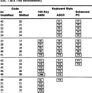
Table 3-1 Key Codes
the direction is normal. key definitions are sent according to the terminal's current communications mode.
Ps2 Direction
o
Remote (default) 1 ~ortnal2 Local
I
identifies this control string as a DECUDK.ke specifies the key being defined (see Thble 3-1).
he is a string of 2-digit hexadecimal codes (each digit in the 0-9 or
A-F range) representing the ASCII values of the character string to be loaded into the key.
ST is the string terminator. ST is a Cl 8-bit control character (use ESC \ in a 7-bit environment)
Code Keyboard Style
kc kc 105-Key Enhanced
Unshlfted Shifted ANSI ASCII PC
42 22
I:KI
[E]
51 31 @] @J
52 32 @] @]
53 33 ~
[E]
54 34 [ill
[EI
37 17 IT!] IT!] ~
38 18
f!!J
f!!J
[!U39 19 @] @]
[!!]
40 20 ~ ~
£Kl
41 21 ~ ~ ~
43 23
[!ill
rEI] [!ill44 24 ~ ~ ~
45 25 [§J [§J
46 26
[!EJ
~48 28
I
HelpI
~49 29
[EI
[!!!]
51 31
lm
52 32 ~
53 33 ~
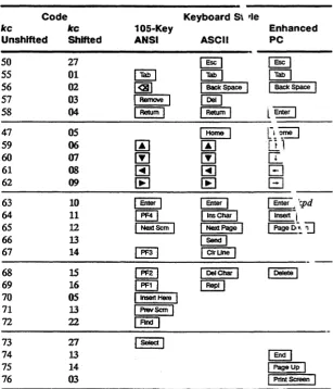
Table 3-1 Key Codes, Code Keyboard St 'Ie
Continued kc kc 105-Key Enhanced
Unshlfted Shifted ANSI ASCII PC
50 27 ~ ~
55 01
IB
IB
I
TabI
56 02 @!]
I
Back SpaceI I
Back SpaceI
57 03
I
RemoveI
~58 04
I
Retum II
Retum Il
Enter I47 05
I
Home !
[~:~59 06
00
00
[jJ
60 07 [Y] [Y]
IT.
61 08 ~ ~
B
62 09
lEI
lEI
El
63 10 I Enter
I
I
EnterI
I
Enter _ 'r;pd64 11
I
PF41
I
Ins CharI
1111$811-1 65 12I
NextScmI
I
NextPageI
1 Page[>~ ~66 13 1 Send I
67 14
I
PF31
I
ClrUneI
68 15
I
PF2!
I
OeICharI
1 [>elate I69 16 ~ 1 Rep"
70 05
I
1nser1 HereI
71 13
I
PrevScmI
72 22 ~
73 27
I
SelectI
74 13
EEl
75 14
I
PageUpI
76 03
I
PrInt ScreenI
You can specify multiple kc/hc parameters by separating them with semicolons (;).
A maximum of 512 bytes can be used for function key definitions, with a maximum of 78 bytes for any single function key.
Examples of DECUDK The sequence
Device Control Strings
DCS 0; 1 1ST
The sequence
DCS 1 ; 0 1ST
locks the current user-defined key definitions.
The sequence
DCS1;1118/4C4F47494E2048454C454EOD;38/4C4F474F 55540DST
• Clears only keys being redefined • Does not lock the new key definitions
• Loads the code for LOGIN HELEN CR into I}§] @] • Loads the code for LOGOUT CR into @]
Until the keys are redefined, pressing
G§J
@] is the same as entering LOGIN HELEN, followed by a carriage return, and pressing IE] is the same as entering LOGOur. followed by a carriage return.---
NUt! iF,lC KEYPAD FUl\: ."~ iONSThe numeric keypad operates in two modes: application mode or numeric mode. These modes are selectable in setup mode
(Numeric Keypad setup parameter) or with an escape sequence. In either mode, numeric keypad keys generate predefined codes.
S M cting Numeric Keypad Modes
DECKPAM Select numeric keypad application mode ESC =
DECKPNM Select numeric keypad numeric mode ESC >
In numeric mode the keys send the standard ASCII character codes represented on the keycaps. Table D-S in Appendix D lists the application mode codes.
RELATED FUNCTIONAL MODE COMMANDS
DECARM Key autorepeat mode
DECBKM Delete key redermition mode
DECCKM Cursor key application mode
DECKBUM Key legend mode
DECNKM Keypad application mode
DECNRCM National replacement character mode
KAM Keyboard lock mode
LNM Newline mode
WYDELKM Delete key redefiDition mode
Set: CSI? 8 h Reset: CSI ? 8 I
Set: CSI ? 67 h Reset: CSI ? 67 I
Set: CSI? 1 h Reset: CSI ? 1 I
Set: CSI ? 68 h Reset: CSI ? 68 I
Set: CSI ? 66 h Reset: CSI ? 66 I
Set: CSI ? 42 h Reset: CSI ? 42 I Set: CSI 2 h Reset: CSI 21
Set: CSI20 h Reset: CSI 20 I
INTRODUCTION
DISPLAYING CHARACTER SETS
Character Sets
This chapter describes the terminal's predefined character sets and explains how to derme and load softfont characters.
Predefined character sets are illustrated in Appendix A
The character displayed on the screen depends on four variables:
• The currently labeled character set • The currently assigned font bank
• The screen resolution (character cell size) • The ASCII code of the character
The default screen resolution is 16x16 (74 Hz). The user can select a 16x20 screen resolution (60 Hz) from setup mode.
o
Note At 74 Hz the screen is refreshed at a higher rate than at 60 Hz, eliminating screen flicker.Two different character sets can be loaded into display memory at one time. The two sections of memory reserved for these character sets are referred to as GL (graphic left) and GR (graphic right). The GL memoty area corresponds to the 7-bit ASCII character codes 21H through 7EH for character sets having 94 characters and 20H through 7FH for character sets having 96 characters. The GR memory area corresponds to the 8-bit ASCII character codes AIH through FEH for 94-character sets and AOH through FFH for 96-character sets.
Figure 4-1 Labeling Character Sets and Assigning Font Banks
1 One escape sequence labels a specified character set as one of four font banks: GO, G 1, G2, or G3.
2 Another escape sequence assigns the font bank to the GL or GR memory area.
Figure 4-1 shows a conceptual diagram for labeling character sets and assigning font banks into GL and GR.
Assigning
Font Banks
Labeling
Control Codes
(7-Bit)
CO
Character Sets - -... ~.
(e.g .• ASCII.
Softfonts)
Character Codes (7-or 8-Blt)
Control
Codes (8-BIt)
GL~~
...
II
Character Codes (8-Bit)
Table 4-1 Default Character Sets
Selecting a User-Preferred Supplemental Character Set
DECAUPSS
DECAUPSS
Labeling Character Sets
SCS
Table 4-1 lists the default predefined character sets in each personality.
Default
Personality Character Set Labeled Assigned
Wyse 370 ···ASCn GO, G1 GO to GL
User-Preferred G2,G3 G2toGR Supplemental·
VT320NT22Q -==~ ASCn GO, G1 GO to GL and Intecolor User-Preferred G2, G3 G2toGR
-
Supplemental·VT100 ASCn GO, G1 GO to GL
VT52 ASCn N/A N/A
• Default is MultiuatiODal Supplemental
In the native or Vf320NT220 personality you can select either the Multinational Supplemental (default) character set or the ISO Latin-l character set as your 8-bit user-preferred supplemental character set.
Select Multinatioaal Supplemental
Des
O! u % 5 ST as the user- preferred supplemental setSelect ISO Latin-1 Supplemental
Des
I! uA STas the user-preferred supplemental set
The SCS escape sequence labels a specified character set as one of four font banks.
Label character set
Ese
/code scodewhere fcode indicates the font bank (GO, Gl, G2, or G3).
fcode
( )
•
+
/
Font Bank
GO (94-character set) G 1 (94-character set) G2 (94-character set) G3 (94-character set)
scode identifies the character set to be loaded in the font bank. Parameter values are listed in two groups. The second group is valid only when national replacement character set mode is set (DECNRCM) and when the language has been selected in setup mode (Keyboard Language setup parameter). Only one national replacement character (NRC) set is available at a time.
scode
o
A B < %5 name scode A 4 CorS R Qor9 K y XE or6 or' %6 Z Hor7
=
Character Set Special GraphicsISO Latin-l Supplemental (96-character set; native and
~320!V1r22Oonly)
ASCII
User-preferred supplemental
In native or ~320NT220 personality, either the Multinational Supplemental or the ISO Latin-l set, depending on the current selection in setup mode or by the DECAUPSS command
Multinational Supplemental (native and VT320NT220 only)
Softfont name assigned by the name parameter in the softfont load command (DECDLD)
NRC Character Set
UK Dutch Finnish French/Belgian French Canadian German Italian
Latin American Spanish Norwegian/Danish Portuguese Spanish Swedish Swiss
Assigning Font Banks
Examples
SiorLS1 SO or LSO LS1R LS2 LS2R LS3 LS3R 'SS2
SS3
CREATING AND LOADING SOFTFONTS
Overview
Once a character set is labeled, you can assign it to the GL or GR memory area with one of the following escape or control
sequences:
Assign GO character set to GL CTRL 0
Assign Gl character set to GL CTRL N
Assign Gl character set to GR Assign GZ character set to GL Assign GZ character set to GR Assign G3 character set to GL Assign G3 character set to GR
Assign GZ character set to GL for the next character only Assign G3 character set to GL for the next character only
ESC
-ESCn
ESC}
ESC 0
ESC
I
ESCNESC 0
Suppose you want to gain access to the special line-drawing characters in the 94-character Special Graphics character set (see Appendix A). To display the Special Graphics character set for ASCII codes 21H through 7EH (GL memory area),
1 Label the Special Graphics set as G 1 ESC) 0
2 AsSign G1 to GL CTRL N
3 Send characters (7 bit)
To display the 96-character ISO Latin-l Supplemental character set for ASCn codes AOH through FFH (GR memory area),
1 Label the ISO Latin-l set as G3 ESC I A
2 Assign G3 to GR ESC
I
3 Send characters (8 bit)
The terminal stores user-definable character sets in a font bank called a soft/onto Initially, all character positions in the softfont are displayed as reverse question marks (.).
o
Note Softfonts are not supported in VTS2 or VT100 personalities.The display of softfonts depends on the screen resolution selected and the number of columns displayed. No softfonts are available in
Designing and Encoding the Softfont Character
lines. In the default 16x16 (74 Hz) resolution, the SO-column softfonts are not interchangeable with those for a 132- or 161-column screen.
Screen Resolution
In 16x16 (74 Hz) screen resolution, you can design softfonts for an SO-column screen and for a 132-column or 161-column screen. An SO-column screen requires its own softfont; the softfont loaded for an 80-column screen cannot be displayed on a screen which has been defmed as 132 or 161 columns. However, a softfont designed for a 132-column screen can be displayed on a 161-column screen. The terminal automatically switches to the correct softfont when the column width is changed. .
Creating the Softfom To create your own softfont,
1 Design the individual characters, as descnbed in the next section, and encode their description in ASCII format so the terminal can recognize them.
2 Load the characters into the softfont with the DECDLD device control sequence, as described in the subsequent section called "Loading a Softfont."
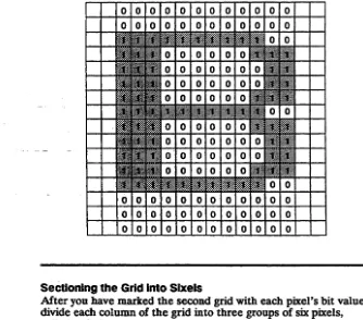
Characters displayed on the screen are patterns of illuminated and nonilluminated pixels (picture elements). A pixel is the smallest unit of the display that can be turned on (illuminated) or off. Each character is designed to fit into a block of pixels called a character cell. The area of the cell that contains the pattern of the character is called the character matrix.
Designing a softfont character and encoding it for the terminal consists of the following steps:
1 Determine the character cell size.
2 Determine the character matrix size.
3 Diagram the character on a grid representing the pixels in the character cell.
4 Mark the grid with 1's and O's, assigning a value of 1 to the "on" pixels and a value of 0 to the "off" pixels to represent the bit pattern of the character.
Table 4-2 Cell Sizes
Table 4-3 Maximum Matrix Sizes
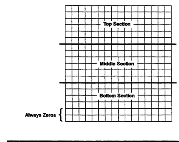
6 Convert the binary number for each sixel to an ASCII character equivalent.
7 List the ASCII characters in a string that completely describes the character to be loaded into the softfont.
Determining the Character Cell Size
Thble 4-2 shows the character cell size for each configuration of screen lines and columns_
Screen Size Cell Size (Pixels)
Lines Columns Width Height
26
52
80 132 161
80 132 161
16 10 8 16 10 8
Determining the Character Matrix Size
16 16 16
8 8 8
The size of the actual character matrix varies according to the cell size and the type of character you are designing (text or
line-drawing). Table 4-3 lists maximum character matrix dimensions.
§!S£r~~n §!Iz~ ~haraS£!~r Mi!trlx Width Character Unes Columns Cell Size Text' Une-Drawlng2 Matrix Height
26 80 16x16 12 16 16
132 1Ox16 7 10 16
161 8x16 7 8 16
52 80 16x8 12 16 8
132 10x8 7 10 8
161 8x8 7 8 8
1. When text all is selected in DECDID command. 2. When full all is selected in DECDID command.
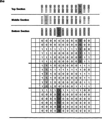
Figure 4-2 Typical Character Matrixes (16x16 Cell)
Figure 4-2 shows the character matrix for a typical text character (uppercase B) and a typical line-drawing character in a 16x16 cell.
In deciding the width and height of the character matrix, you must take into account a basic difference between text and line-drawing characters. A line-drawing character typically extends to the outside edge of the cell so adjoining line-drawing characters can touch it in order to draw a graphic shape. But text characters require spacing between each character, so part of each cell must be left empty to create that space.
Table 4·4 Maximum Width of Text Characters
Screen Total Blank
Columns Cell Width Cell Columns*
80 16 pixels 1,2, 15, 16
132 10 1,9,10
161 8 1
• By column number, starting at the left side of the cell
Diagramming a Character To diagram a character,
Maximum Character Width
12
7 7
1 Draw a grid to represent each pixel in the character cell and map the "on" pixels that define the pattern of the character.
2 Draw a duplicate blank grid and translate the pattern from the first grid into the blank grid by marking I's for eac