ISSN(Online): 2319-8753
ISSN (Print): 2347-6710
I
nternational
J
ournal of
I
nnovative
R
esearch in
S
cience,
E
ngineering and
T
echnology
(An ISO 3297: 2007 Certified Organization)
Vol. 5, Special Issue 4, March 2016
Multi Fault Detection and Correction Using
Error Correction Codes and Parseval Checks
Ranjani.S1, M.Monika2
PG Scholar, Department of ECE,Sri Krishna College of Engineering and Technology, Coimbatore, India1
Assistant Professor, Department of ECE, Sri Krishna College of Engineering and Technology, Coimbatore, India 2
ABSTRACT: Digital filters are widely used in signal processing and communication systems. In some cases, the reliability of those systems is critical, and fault tolerant filter implementations are needed. Over the years, many techniques that exploit the filters’ structure and properties to achieve fault tolerance have been proposed. As technology scales, it enables more complex systems that incorporate many filters. In those complex systems, it is common that some of the filters operate in parallel, for example, by applying the same filter to different input signals. For some applications, an interesting option is to use algorithmic-based fault tolerance (ABFT) techniques that try to exploit the algorithmic properties to detect and correct errors. Signal processing and communication applications are well suited for ABFT. Recently, a simple technique that exploits the presence of parallel filters to achieve fault tolerance has been presented. In this brief, that idea is generalized to show that parallel filters can be protected using many techniques in which each filter is the equivalent of a bit in a traditional ECC. This new scheme allows more efficient protection when the number of parallel filters is large. The technique is evaluated using a case study of parallel finite impulse response filters, Error correction codes (ECCs), parseval checks, showing the effectiveness in terms of protection and implementation cost.
KEYWORDS: Error correction codes (ECCs), fast Fourier transforms (FFTs), soft errors, parseval checks, Parity-SOS-ECC.
I. INTRODUCTION
The complexity of communications and signal processing circuits increases every year. This is made possible by the CMOS technology scaling that enables the integration of more and more transistors on a single device. This increased complexity makes the circuits more vulnerable to errors. At the same time, the scaling means that transistors operate with lower voltages and are more susceptible to errors caused by noise and
Manufacturing variations. The importance of radiation-induced soft errors also increases as technology scales [2]. Soft errors can change the logical value of a circuit node creating a temporary error that can affect the system operation. To ensure that soft errors do not affect the operation of a given circuit, a wide variety of techniques can be used [3]. These include the use of special manufacturing processes for the integrated circuits like, for example, the silicon on insulator. Another option is to design basic circuit blocks or complete design libraries to minimize the probability of soft errors. Finally, it is also possible to add redundancy at the system level to detect and correct errors.
ISSN(Online): 2319-8753
ISSN (Print): 2347-6710
I
nternational
J
ournal of
I
nnovative
R
esearch in
S
cience,
E
ngineering and
T
echnology
(An ISO 3297: 2007 Certified Organization)
Vol. 5, Special Issue 4, March 2016
the protection of digital filters [5], [6]. For example, the use of replication using reduced precision copies of the filter has been proposed as an alternative to TMR but with a lower cost [7]. The knowledge of the distribution of the filter output has also been recently exploited to detect and correct errors with lower overheads [8]. The protection of fast Fourier transforms (FFTs) has also been widely studied. As signal-processing circuits become more complex, it is common to find several filters or FFTs operating in parallel.
The presence of parallel filters or FFTs creates an opportunity to implement ABFT techniques for the entire group of parallel modules instead of for each one independently. This has been studied for digital filters initially in [16] where two filters were considered. More recently, a general scheme based on the use of error correction codes (ECCs) has been proposed [17]. In this technique, the idea is that each filter can be the equivalent of a bit in an ECC and parity check bits can be computed using addition. This technique can be used for operations, in which the output of the sum of several inputs is the sum of the individual outputs. This is true for any linear operation as, for example, the discrete Fourier transforms (DFT).
II. EXISTING SYSTEM
2.1 PARALLEL FFT PROTECTION USING ECCs
This technique provides new alternatives to protect parallel FFTs that can be more efficient than protecting each of the FFTs independently.
Fig 2.1. Parallel FFT protection using ECCs
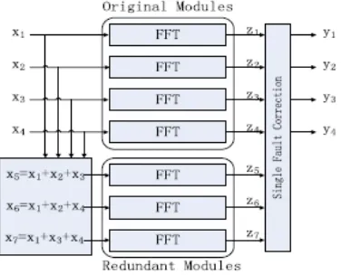
The starting point for our work is the protection scheme based on the use of ECCs that was presented in [17] for digital filters. This scheme is shown in Fig. 1. In this example, a simple single error correction Hamming code [18] is used. The original system Consists of four FFT modules and three redundant modules is added to detect and correct errors. The inputs to the three redundant modules are linear combinations of the inputs and they are used to check linear combinations of the outputs. For example, the input to the first redundant module is
x5 = x1 + x2 + x3 (2.1)
and since the DFT is a linear operation, its output z5 can be used to check that
z5 = z1 + z2 + z3 (2.2)
This will be denoted as c1 check. The same reasoning applies to the other two redundant modules that will
provide checks c2 and c3.Based on the differences observed on each of the checks, the module on which the error has
occurred can be determined. The different patterns and the corresponding errors are summarized in Table I. Once the module in error is known, the error can be corrected by reconstructing its output using the remaining modules. For
example, for an error affecting z1, this can be done as follows:
z1c[n] = z5[n] − z2[n] − z3[n] (2.3)
ISSN(Online): 2319-8753
ISSN (Print): 2347-6710
I
nternational
J
ournal of
I
nnovative
R
esearch in
S
cience,
E
ngineering and
T
echnology
(An ISO 3297: 2007 Certified Organization)
Vol. 5, Special Issue 4, March 2016
in [17], is lower than TMR as the number of redundant FFTs is related to the logarithm of the number of original FFTs. For example, to protect four FFTs, three redundant FFTs are needed, but to protect eleven, the number of redundant FFTs in only four. This shows how the overhead decreases with the number of FFTs.
Table.2.1. Error location in the hamming code
2.2 PARITY-SOS FAULT-TOLERANT PARALLEL FFTS
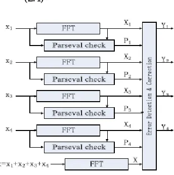
Many techniques have been proposed to protect the FFT. One of them is the Sum of Squares (SOSs) check [4] that can be used to detect errors. The SOS check is based on the Parseval theorem that states that the SOSs of the inputs to the FFT are equal to the SOSs of the outputs of the FFT except for a scaling factor. This relationship can be used to detect errors with low overhead as one multiplication is needed for each input or output sample (two multiplications and adders for SOS per sample).
For parallel FFTs, the SOS check can be combined with the ECC approach to reduce the protection overhead.
Since the SOS check can only detect errors, the ECC part should be able to implement the correction. This can be done using the equivalent of a simple parity bit for all the FFTs. In addition, the SOS check is used on each FFT to detect errors. When an error is detected, the output of the parity FFT can be Redundant (the parity) FFT is added that has the sum of the inputs to the original FFTs as input. An SOS check is also added to each original FFT. In case an error is detected (using P1, P2, P3, P4), the correction can be done by recomposing the FFT in error using the output of the parity FFT(X) and the rest of the FFT outputs. For example, if an error occurs in the first FFT, P1 will be set and the error can be corrected by doing
x1c = x − x2 − x3 − x4 (2.4)
ISSN(Online): 2319-8753
ISSN (Print): 2347-6710
I
nternational
J
ournal of
I
nnovative
R
esearch in
S
cience,
E
ngineering and
T
echnology
(An ISO 3297: 2007 Certified Organization)
Vol. 5, Special Issue 4, March 2016
This combination of a parity FFT and the SOS check reduces the number of additional FFTs to just one and may, therefore, reduce the protection overhead. In the following, this scheme will be referred to as parity-SOS.
2.3 PARITY-SOS-ECC FAULT-TOLERANT PARALLEL FFTS
This combination of parity FFT and the SOS check reduces the number of additional FFTs to just one and may, therefore, reduce the protection overhead. In the following, this scheme will be referred to as parity-SOS (or first proposed technique).
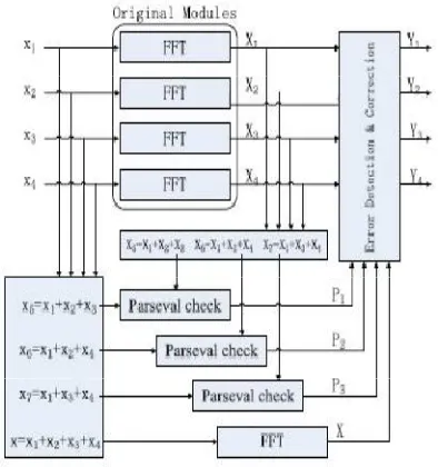
Another possibility to combine the SOS check and the ECC approach is instead of using an SOS check per FFT, use an ECC for the SOS checks. Then as in the parity-SOS scheme, an additional parity FFT is used to correct the errors. The main benefit over the first parity-SOS scheme is to reduce the number of SOS checks needed. The error location process is the same as for the ECC scheme in Fig. 1 and correction is as in the parity-SOS scheme. In the following, this scheme will be referred to as parity-SOS-ECC .
The overheads of the two proposed schemes can be initially estimated using the number of additional FFTs
and SOS check blocks needed. This information is summarized II for a set of k original FFT modules assuming k is a
power of two. It can be observed that the two proposed schemes reduce the number of additional FFTs to just one. In addition, the second technique also reduces the number of SOS checks. In Section III, a detailed evaluation for an FPGA implementation is discussed to illustrate the relative overheads of the proposed techniques.
Fig 2.3. parity-SOS-ECC fault-tolerant parallel FFT
ISSN(Online): 2319-8753
ISSN (Print): 2347-6710
I
nternational
J
ournal of
I
nnovative
R
esearch in
S
cience,
E
ngineering and
T
echnology
(An ISO 3297: 2007 Certified Organization)
Vol. 5, Special Issue 4, March 2016
Finally, errors on the detection and correction blocks in Figs. 2 and 3 can propagate errors to the outputs. In our implementations, those blocks are protected with TMR. The same applies for the adders used to compute the inputs to the redundant FFTs in Fig. 1 or to the SOS checks in Fig. 3. The triplication of these blocks has a small impact on circuit complexity as they are much simpler than the FFT computations.
A final observation is that the ECC scheme can detect all errors that exceed a given threshold (given by the quantization used to implement the FFTs) [17]. On the other hand, the SOS check detects most errors but does not guarantee the detection of all errors [4]. Therefore, to compare the three techniques for a given implementation, fault injection experiments should be done to determine the percentage of errors that are actually corrected. This means that an evaluation has to be done both in terms of overhead and error coverage.
III. PROPOSED SYSTEM
3.1 PARALLEL CORRECTION METHOD
In this method, we are using parseval check method to detect the errors in the original module. By using this
method we can able to detect more than one error in the original modlue . After that redundant modules are is used to correct those errors.
Fig.3.1. Parallel correction method
In partial summation method, we just add the inputs of the FFTs and it will be compare with the first output of the FFTs. In case, these two values are equal no errors in that particular FFT. If it is not equal threes is an error in that FFT. In this method, original module is enough to detect the errors in the FFTs. So, that no need for additional detection circuits. For that reason area and power will be effectively reduced in this method.
ISSN(Online): 2319-8753
ISSN (Print): 2347-6710
I
nternational
J
ournal of
I
nnovative
R
esearch in
S
cience,
E
ngineering and
T
echnology
(An ISO 3297: 2007 Certified Organization)
Vol. 5, Special Issue 4, March 2016
the SOS checks in Fig. 3. 1.The triplication of these blocks has a small impact on circuit complexity as they are much simpler than the FFT computations.
Fig.3.1.2. Implementation of the SOS checks
A final observation is that the ECC scheme can detect all errors that exceed a given threshold (given by the quantization used to implement the FFTs) [17]. On the other hand, the SOS check detects most errors but does not guarantee the detection of all errors [4]. Therefore,to compare the three techniques for a given implementation, fault injection experiments should be done to determine the percentage of errors that are actually corrected. This means that an evaluation has to be done both in terms of overhead and error coverage.
IV. RESULTS AND DISCUSSION
ISSN(Online): 2319-8753
ISSN (Print): 2347-6710
I
nternational
J
ournal of
I
nnovative
R
esearch in
S
cience,
E
ngineering and
T
echnology
(An ISO 3297: 2007 Certified Organization)
Vol. 5, Special Issue 4, March 2016
Table.4.1. Comparison Table
ECC
PARITY-SOS
PARITY-SOS-ECC
Gate count
16735
10561
9584
Flipflops 392 236 225
LUT 612 508 388
Slices 419 331 284
Power (mW)
263 253 252
The objective is to illustrate how the relative overheads of the different techniques vary with the number of parallel FFTs. In parentheses, the cost relative to an unprotected implementation is also provided. The results show that all techniques have a cost factor of <2. This demonstrates that the ECC-based
technique proposed in [17] is also competitive to protect FFTs and requires a much lower cost than TMR. The parity-SOS-ECC technique has the lowest resource use in all cases and, therefore, is the best option to minimize the implementation cost. This is expected from the discussion in Section II and the initial estimates presented in Table II. On the other hand, the parity-SOS scheme needs less resources than the ECC scheme when the number of FFTs is 4, 6, or 8 but more when the number of FFTs is 11. This can be explained as in the ECC scheme, the number of additional FFTs grows logarithmically with the number of FFTs, while in the
parity-SOS technique, the number of SOS checks grows linearly.This means that as the number of FFTs to protect increases, the ECC scheme becomes more competitive. For the parity-SOS-ECC scheme, the number of SOS checks also grows logarithmically and
they are simpler to implement than FFTs.
V. CONCLUSION
The protection of parallel FFTs execution against soft errors has been studied. Two techniques have been proposed and evaluated. The proposed techniques are based on combining an existing ECC approach with the traditional SOS check. The SOS Checks are used to detect and locate the errors and a simple parity FFT is used for correction. The detection and location of the errors can be done using an SOS check per FFT or alternatively using a set of SOS checks that form an ECC. The proposed techniques have been evaluated both in terms of implementation complexity and error detection capabilities. The results show that the second technique, which uses parity FFT and a set of SOS checks that form an ECC, provides the best results in terms of implementation complexity and finding more than one errors. In terms of error protection, fault injection experiments show that the ECC scheme can recover all the errors that are out of the tolerance range. The fault coverage for the parity-SOS scheme and the parity-SOS-ECC scheme is 99.9% when the tolerance level for SOS check is 1.
REFERENCES
1. R. Baumann, “Soft errors in advanced computer systems,” IEEE Des.Test Comput., vol. 22, no. 3, pp. 258–266, May/Jun. 2005. 2. M. Nicolaidis, “Design for soft error mitigation,” IEEE Trans. Device Mater. Rel., vol. 5, no. 3, pp.405–418, Sep. 2005.
ISSN(Online): 2319-8753
ISSN (Print): 2347-6710
I
nternational
J
ournal of
I
nnovative
R
esearch in
S
cience,
E
ngineering and
T
echnology
(An ISO 3297: 2007 Certified Organization)
Vol. 5, Special Issue 4, March 2016
4. T. Hitana and A. K. Deb, “Bridging concurrent and non-concurrent error detection in FIR filters,” in Proc. Norchip Conf., Nov. 2004, pp. 75– 78.
5. S. Pontarelli, G. C. Cardarilli, M. Re, and A. Salsano, “Totally fault tolerant RNS based FIR filters,” in Proc. 14th IEEE Int. On-Line Test Symp. (IOLTS), Jul. 2008, pp. 192–194.
6. B. Shim and N. R. Shanbhag, “Energy-efficient soft error-tolerant digital signal processing,” IEEE Trans. Very Large Scale Integr. (VLSI) Syst., vol. 14, no. 4, pp. 336–348, Apr. 2006.
7. E. P. Kim and N. R. Shanbhag, “Soft N-modular redundancy,” IEEE Trans. Comput., vol. 61, no. 3, pp. 323–336, Mar. 2012. 8. J. Y. Jou and J. A. Abraham, “Fault-tolerant FFT networks,” IEEE Trans. Comput., vol. 37, no. 5, pp. 548–561, May 1988.
9. S.-J. Wang and N. K. Jha, “Algorithm-based fault tolerance for FFT networks,” IEEE Trans. Comput., vol. 43, no. 7, pp. 849–854, Jul. 1994.
10. P. P. Vaidyanathanm, Multirate Systems and Filter Banks.Englewood Cliffs, NJ, USA: Prentice-Hall, 1993.
11. Sibille, C. Oestges, and A. Zanella, MIMO: From Theory to Implementation. San Francisco, CA, USA: Academic, 2010.
12. G. L. Stüber, J. R. Barry, S. W. McLaughlin, Y. Li, M. A. Ingram, and T. G. Pratt, “Broadband MIMO-OFDM wireless communications,” Proc.IEEE, vol. 92, no. 2, pp. 271–294, Feb. 2004.
13. S. Sesia, I. Toufik, and M. Baker, LTE—The UMTS Long Term Evolution:From Theory to Practice, 2nd ed. New York, NY, USA: Wiley,Jul. 2011.
14. M. Ergen, Mobile Broadband—Including WiMAX and LTE. New York, NY, USA: Springer-Verlag, 2009.
15. P. Reviriego, S. Pontarelli, C. J. Bleakley, and J. A.Maestro, “Area efficient concurrent error detection and correction for parallel filters,” IET Electron. Lett., vol. 48, no. 20, pp. 1258–1260, Sep. 2012.
16. Z. Gao et al., “Fault tolerant parallel filters based on error correction codes,” IEEE Trans. Very Large Scale Integr. (VLSI) Syst., vol. 23, no. 2, pp. 384–387, Feb. 2015.
17. R. W. Hamming, “Error detecting and error correcting codes,” Bell Syst. Tech. J., vol. 29, no. 2, pp. 147–160, Apr. 1950.