ISSN(Online): 2319-8753 ISSN (Print): 2347-6710
I
nternational
J
ournal of
I
nnovative
R
esearch in
S
cience,
E
ngineering and
T
echnology
(A High Impact Factor, Monthly, Peer Reviewed Journal)
Visit: www.ijirset.com
Vol. 8, Issue 5, May 2019
A Smart Notice Board System Using IoT
Technology
S.Gladson #1, G.Brindha *2
Associate Professor, Department of ECE, Sasurie College of Engineering, Vijayamangalam, Tirupur,
Tamilnadu, India#1
II-M.E-VLSI Design, Department of ECE, Sasurie College of Engineering, Vijayamangalam, Tirupur,
Tamilnadu, India*2
ABSTRACT: Digital Notice board is used in institution or organization or public utility places like College campus,
railway stations etc., but Sending and monitoring various notices every day is a heavy process. A separate person is required to take care of these notices. This paper deals with advanced notice board. Our proposed system will enable people to wireless transmit notices on a notice board using GSM with smart Phone and users get auto notification using parse cloud. Its operation is based on microcontroller ATMEGA 328 Programmed in C language. When the user sends notice via registered smart Phone that message will get display on the notice board simultaneously through the parse cloud other users get auto notification on their smart Phone. We can also makethe system compatible with more than one wireless technology. The numbers of notice boards are connected in IOT to get the status of the notice boards automatically to the cellular device.
KEYWORDS: GSM Module, P10 LED Display, Smart Phoneud, IoT (Internet of Things)
I. INTRODUCTION
Now-a-days advertisement is going digital. The big shops and the shopping centers use digital displays now. Also, in trains and buses the information like platform number, ticket information is displayed in digital boards. People are now adapted to the idea of the world at its finger-tips. The use mobile P10ones have increased drastically over years. Control and communication has become important in all the parts of the world. This gave us the idea to use mobile P10ones to receive message and then display it on an electronic board. The GSM technology is used. GSM stands for GlobalSystem for Mobile Communication. Due to this international roaming capability of GSM, we can send message to receiver from any part of the world. It is has the system for SMS-Short Message Service. This Paper is a remote notice board with a GSM modem at the receivers end. So if the user wants to display any message, he can send the information by SMS and thus update the LED display accordingly. As engineer’s main aim is to make life simple with help of technology, this is one step to simplify real time noticing.
ISSN(Online): 2319-8753 ISSN (Print): 2347-6710
I
nternational
J
ournal of
I
nnovative
R
esearch in
S
cience,
E
ngineering and
T
echnology
(A High Impact Factor, Monthly, Peer Reviewed Journal)
Visit: www.ijirset.com
Vol. 8, Issue 5, May 2019
time. The limitations can be removed by the use of higher end microcontrollers and extended RAM. The prototype can be implemented using commercial display boards. The use of “Embedded System in Communication” has given rise to manyinteresting
II. LITERATURE REVIEW
The detailed survey of various literals for the execution of the project is presented in this chapter.Moore's law states that the number of transistors that could be integrated into a single die would grow exponentially with time. Thus this causes increasing computational complexity of the chip and physical limitations of devices such as power consumption, interconnect will become very difficult.According to recent analysis the minimum limit fortransistor size may be reached. Thus, it may not bepossible to continue the rule of Moore's law andthe clock rate for every three years. So in order to overcome this physical limit of CMOS-VLSIdesign an alternative approach is Quantum dot CellularAutomata (QCA). In ALU adder plays a vital role
Inthis survey a binary adder is taken for analysis and anew adder is designed based upon QCA technology.This modified novel bit adder is implemented into ALUstructure. The aim of this proposed technique is that toreducing number of majority gates used in the design.This will lead to reduce number of QCA cells so thattotal area of ALU circuit can be minimized compare toprevious designs. It also achieves reduced powerconsumption and high speed performances than allother existing ALU design which uses normal fulladder
Buzzer
Buzzer is controlled by the microcontroller using single pin. Sometimes it can be interchanged according to the transistor used to drive the device. The buzzer subsystem produces a 2 KHz audible tone when powered. The buzzer will sound when the signal coming into the driver is high. It must be connected to a Darlington transistor or transducer driver subsystem .The buzzer is connected between the supply rail (+ V) and the input signal. This acts as load on the driver. When the input signal coming into the buzzer subsystem is low, a potential difference across the buzzer causes current to flow. It is this flow of current that causes the buzzer to sound. Buzzer is connected to microcontroller port pin, so microcontroller will give high or low to switch
METHODS
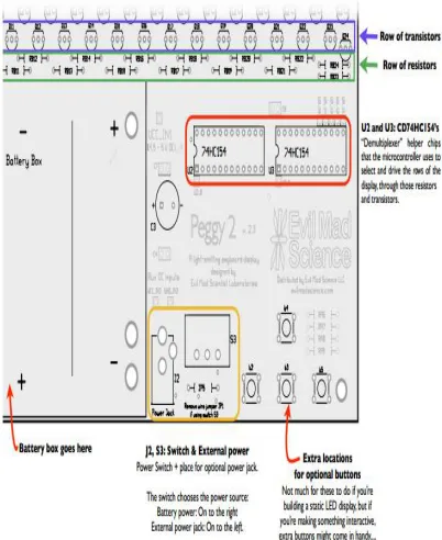
A schematic of the circuitry within Peggy can be found in its datasheet which is referenced in the Bibliography of this report.While this board doesnʼt have the modular capabilities that some of the otheroptions
contained, the open source guide to the processing of the system. The codethat is provided for some of the recommended projects on the site gives a good guidefor the processes that must be completed to produce interesting effects on the matrix.
Another small downside to this product is that the LEDʼs are the globe shaped le available in either 3mm, 5mm, or 10mm sizes. This is sufficient for testing and recreational purposes, but with a display that will be visible in a public place such as Atwater Kent, we want to have a concealed LED section such as that found in the dot matrices from Betlux seen above. Another useful aspect with the open source availability of this product is that wewere easily able to view a schematic diagram of the circuitry, as well as a description ofA schematic of the circuitry within Peggy can be
found in its datasheet which isreferenced in the Bibliography of this report.While this board doesnʼt have the modular
ISSN(Online): 2319-8753 ISSN (Print): 2347-6710
I
nternational
J
ournal of
I
nnovative
R
esearch in
S
cience,
E
ngineering and
T
echnology
(A High Impact Factor, Monthly, Peer Reviewed Journal)
Visit: www.ijirset.com
Vol. 8, Issue 5, May 2019
ISSN(Online): 2319-8753 ISSN (Print): 2347-6710
I
nternational
J
ournal of
I
nnovative
R
esearch in
S
cience,
E
ngineering and
T
echnology
(A High Impact Factor, Monthly, Peer Reviewed Journal)
Visit: www.ijirset.com
Vol. 8, Issue 5, May 2019
III. CHOOSING THE DESIGN
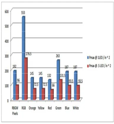
Group found itself with dozens of ideas of how would be able toimplement an interactive and entertaining, yet informative display. At first, not a singleidea accomplished all of the criteria while still remaining feasible under the constraintsthat we were placed under, such as cost, power consumption, and completion time he top part of the display we are proposing to build will be composed of about 60 8x8 RGB LED matrix displays. The model number of these 8x8 displays is BLM23B881RGB-11.
This portion will be set up 2 rows high, and about 30 columns longfinal dimensions of this portion using 60 modules would be about 5 inches by 6 feet).In this section, we plan on displaying information which can scroll across the screensuch as news, temperature readings, etc.
Table LED Display Board Number of Modules
8*8(Dim inches)
8*8(m atrices )
Size(i nches)
Size(f eet)
Rows 2.37 2 4.74 0.315
Colum ns
2.37 30 71.1 5.925
Total moudle
60
In considering the cost for this portion of our MQP, have already purchasednumerous circuitry elements to be used to drive individual modules. estimate thecost per module to come to around $20 to $25 not including the cost for circuit boardfabrication. This cost includes the cost of the LED screen, and all electrical components expect will need to complete one module.
ISSN(Online): 2319-8753 ISSN (Print): 2347-6710
I
nternational
J
ournal of
I
nnovative
R
esearch in
S
cience,
E
ngineering and
T
echnology
(A High Impact Factor, Monthly, Peer Reviewed Journal)
Visit: www.ijirset.com
Vol. 8, Issue 5, May 2019
IV. RESULTS
FUNCTIONALITY TESTING AND RESULTS
This chapter describes the testing that was performed to check the functionalityof the different blocks of our system. Again, a “divide and conquer” style of debugging isvery useful. We also used a breadboarding method of implementation beforecommitting to a PCB design. Evaluating the circuitry and programming using hardwareconfigurations that are easily changed on the breadboard assures us that the otherblocks are functional.
IoT
The Internet of things (IoT) is the inter-networking of physical devices, vehicles, buildings, and other items— embedded with electronics, software, sensors, actuators, and network connectivity that enable these objects to collect and exchange data. The IoT allows objects to be sensed or controlled remotely across existing network infrastructure, creating opportunities for more directintegration of the physical world into computer-based systems, and resulting in improved efficiency, accuracy and economic benefit in addition to reduced human intervention. Here all the digital notice boards are connected through IoT
Fig 4.3.2: STK500 Description Diagram
ISSN(Online): 2319-8753 ISSN (Print): 2347-6710
I
nternational
J
ournal of
I
nnovative
R
esearch in
S
cience,
E
ngineering and
T
echnology
(A High Impact Factor, Monthly, Peer Reviewed Journal)
Visit: www.ijirset.com
Vol. 8, Issue 5, May 2019
roaming agreements exist with a large number of countries and this means users can use GPRS devices whilst broad. GPRS is based on internet Protocols (IP) andenables users to utilize wide range ofapplications–email and internet and/orintranet resources for instance. With throughput rates of upto 40Kbit/s, users have a similar access speed to a dial-up modem, but with the convenience of being able to connect for many where.
Fig 4.3.3 :8x8 Prototype Board with Transistor Arrays
Other information’she other information of the P10 SMI-outdoor green
ISSN(Online): 2319-8753 ISSN (Print): 2347-6710
I
nternational
J
ournal of
I
nnovative
R
esearch in
S
cience,
E
ngineering and
T
echnology
(A High Impact Factor, Monthly, Peer Reviewed Journal)
Visit: www.ijirset.com
Vol. 8, Issue 5, May 2019
The next step from here would be to reconfigure the layout of the entire schematic in multi sim (to fix the pin layout of the 8x8 array), and possibly move the chips around on in ulti board to reduce the complexity of the traces. Additionally, working with surface mount packages (both on the top and bottom of the board) would help reduce the amount of PCB area needed. Also, putting surface mount chips in between the rows of pins for each of the 8x8 arrays on the top and bottom of the board would significantly decrease the size of our boards. Also, on the PCB layout, we would need to move the bypass capacitors to be next to each of the chips to help reduce noise in the PCB. Additionally, adding another layer to the PCB would significantly help reduce the complexity of the traces on the board and would there fore help greatly with reducing the size of the PCB as well.
LONG TERM
In the long term, it would be important to get the main microcontroller block working. A microcontroller would have to be selected that has enough memory to store all intensity bits for all microcontrollers in it at the same time. For example, this microcontroller could be a laptop and microcontroller system. Using a USB interface chip on a separate PCB board, the laptop can be used to communicate with a microprocessor telling it which microprocessor or digital memory to communicate with. Then, the computer can send serial data directly to the activated microprocessor. To select a microprocessor, the same row, column select method can be used as was used to select an individual LED in the 8x8 array. Except in this case, a NAND gate placed at the CS pin of the microprocessor would cause the microprocessor to listen for in coming serial data when the two pins connected to it are set high (one connected to the row it is a part of, and the second connected to the column it is a part of). Updating the data being sent to the display board can be as simple as connecting to an HTTP server running on the laptop and using a variation of the script described in the software section which takes in a string of ASCII characters and spits out the C data representation of what needs to be sent to the microprocessor to display the text supplied to the script.
V. CONCLUSION
The proposed system accepts the message, stores it, validates and displays it on the LED display. LED displays are used to display messages in Railway stations, shopping malls for displaying advertisement, Educational institution and organizations, managing traffic in smart cities and other public utility places. Cost of printing and P10otocopying is also reduced because the information can be delivered to a large number of people in a very short time. It provides faster transfer of information and are easy to install and maintain. This paper provides an efficient way of displaying messages on Notice Board and also gets auto notification using Wireless Technology. It also provides user to easily receive the important information or message.
REFERENCES
[1] Savan Shah.Message Displayed on LCD Screen using GSM and Bluetooth Technology in International Journal of Advanced Research in Computer Communication Engineering. Vol.4, Issue 9, September 2015.
[2] Prof. Sudhir Kadam, Abhishek Saxena, Tushar Gaurav.Android Based Wireless Notice board and Printer in International Journal of Innovative Research in Computer and Communication Engineering.
Vol.3, Issue 12, December 2015
[3] Prof. Ravindra Joshi, Abhishek Gupta, Rani Borkar, Samita Gawas, Sarang Joshi. GSM based Wireless Notice Board in International Journal of Technical Research and Application.Issue 40 (KCCEMSR), March 2016.
ISSN(Online): 2319-8753 ISSN (Print): 2347-6710
I
nternational
J
ournal of
I
nnovative
R
esearch in
S
cience,
E
ngineering and
T
echnology
(A High Impact Factor, Monthly, Peer Reviewed Journal)
Visit: www.ijirset.com
Vol. 8, Issue 5, May 2019
[9] Bhupesh Aneja , Chhavi Srivastav , Kartavya Farashwal , Ajey Aditya “Wireless Electronic Display Board Using GSM Technology”, International journal of advanced technology in Engineering and science, Volume no 4.Issue no 3, March 2016.
[10] Mayur R. Bhoyar, Suraj Chavhan and Vaidehi Jaiswal, (2014) “Secure method of updating digital notice board through SMS with PC monitoring system”, IOSR Journal of Computer Science (IOSRJCE), e-ISSN: 2278-0661, p-ISSN: 2278-872, pg. 24-29.
[11] Nivetha S. R., Puritha R., Preethi Selvaraj and Yashvanthini S. M., (2013) SMS based wireless notice board with monitoring system, International Journal of Advanced Electrical and Electronics Engineering, (IJAEEE), ISSN (Print): 2278-8948, Volume 2, Issue 3, pp 58-62 [12] Anuradha Mujumdar, Vaishali Niranjane & Deepika Sagne, (2014) “Scrolling LED display using wireless transmission”, International Journal of Engineering Development and Research (ISSN: 2321-9939), Volume 2, Issue 1, pp 475-478.
[13] Gowrishankar Kasilingam , Mritha Ramalingam and Chandra Sekar (2014) “A Survey of Light Emitting Diode (LED) Display Board”,Indian Journal of Science and Technology, Vol 7(2), 185–188, February 2014.