Maximum Power Point Optimization of
Photo-voltaic System using Active Disturbance
Rejection Control
Pooja Jha
Assistant Professor, Department of Electrical Engineering, Sandip Foundation’s Sandip Institute of Engineering
Management, Nashik, India
ABSTRACT: Photovoltaic technology based power generation system is the growing form of energy conversion generating system resulting in electrical power output. It is susceptible to the impact of solar radiation, external temperature and seasonal changes. There are many indecisions.Active Disturbance Rejection Control (ADRC) technology if applied to solar PV systems to control of DC-DC Converter can help in performance improvement. In the system model, uncertainties and external disturbances are unified to effect the system with unknown interference. An observer is used for dynamic observation of the disturbances. The nonlinear state error feedback the control strategies are used to compensate the system. So, it doesn’t affect the parameters within the system and unknown disturbance. It will simplify the process of the control system. Simulation results show that the design of ADRC can achieve the desired control effect, and has good stability and robustness.
KEYWORDS: ADRC, Solar PV,.DC-DC Transform
I. INTRODUCTION
When radiation and temperature are given, the power that photovoltaic cell output is closely related to its terminal voltage. Due to the high cost of the photovoltaic power generation system, it is necessary to constantly adjust the terminal voltage of the photovoltaic cell to stabilize its operating point at the maximum power point neighbourhood to improve the utilization of solar energy, which makes the maximum power tracking technology become a very important control strategy in photovoltaic power generation system [1]. At present, the most used methods of the maximum power point tracking (MPPT) algorithm are: perturb and observe, incremental conductance and other methods derive from them. These derived algorithms include the variable step perturb and observe method and the gradient variable step length incremental conductance method [2-3].
II. SOLAR PV SYSTEM MODEL
Fig1 - Solar PV Equivalent Circuit
PV equivalent circuit is shown in the figure below. Many literature study shows the characteristics of photovoltaic cells, under higher light intensity, that the greater the solar cell output current, higher output power, and open circuit voltage is slightly increased, which if the higher the temperature of solar cells, that the smaller the output voltage, output power of more low, but the short circuit current is a slight increased.According to the Kirchhoff laws, the I-V equation for photovoltaic cell is given by:
Where
I
ph is the current of light-sensitive diode D,I
dis the current through p-n junction, V is the photovoltaic cell output voltage, I for the photovoltaic cell output current, Rshrepresents the parallel resistance, and it is inverselyproportional to the current that the battery leakage to theground, Rs is the series resistance of the cell, T is the
thermodynamic temperature of the battery, n is the diode quality factor, q is the electrical charge of electron,q
=1.602×10⁻¹⁹ C , k is the Boltzmann constant, k =1.381×10⁻²³ J K and Nsis the number of series PV units.Isatis the
inverse saturation current and it could be calculated by:
Where,T0 is the reference temperature of cell, I0 is the inverse saturation current of PV cell in T0 and
E
gap is the air–gap
voltage of p-n junction in PV array.
III. MPPT CONTROL ALGORITHM
The weather and load changes cause the operation of a PV system to vary almost all the times. A dynamic tracking technique is important to ensure maximum power is obtained from the photovoltaic arrays. The following algorithms are the most fundamental MPPT algorithms, and they can be developed using micro controllers.The MPPT algorithm operates based on the truth that the derivative of the output power (P) with respect to the panel voltage (V) is equal to zero at the maximum power point. In the literature, various MPP algorithms are available in order to improve the performance of photovoltaic system by effectively tracking the MPP. However, most widely used MPPT algorithms are considered here, they are:
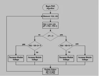
a) Perturb and Observe (P &O)
Fig-2 Graph Power versus Voltage for Perturb and Observe Algorithm
Figure 3. P&O Algorithm
this perturbation also the fails to track the maximum power under fast changing atmospheric conditions. But remain this technique is very popular and simple.
b) Incremental Conductance (IC)
The perturb oscillation around peak power point of perturb and observe method to track the peak power under fast varying atmospheric condition is overcome by IC method. The Incremental Conductance can determine that the MPPT has reached the MPP and stop perturbing the operating point. If this condition is not met, the direction in which the MPPT operating point must be perturbed can be calculated using the relationship between dI/dV and –I/V This relationship is derived from the truth that dP/dV is negative when the MPPT is to the right side curve of the MPP and positive when it is to t he left side curve of the MPP. This algorithm has ad vantages over P&O in that it can determine when the MPPT has reached the MPP, where P&O oscillates around the MPP. Also, incremental conductance can track rapidly increasing and decreasing irradiance conditions with higher precision than perturb and observe. The disadvantage of this algorithm is the increased complexity.
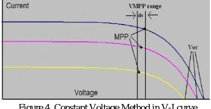
c) Constant Voltage Method
The Constant Voltage method (CV), also in some literature called Open voltage Ratio method, uses the fact that the MPP voltage at different irradiance is approximately equal.
Figure 4. Constant Voltage Method in V-I curve
VOC represented the open circuit voltage of the PV panel. VOC depends on the property of the solar cells. A commonly used VOC/VMPP value is 76%. This relationship can be described by equation below:
VMPP = k * VOC where k ≈0.76 in this case.
The solar panels are always disconnected from the converter circuit for a short duration of time for VOC measurement. The operating voltage of the MPP is then set to 76% of the measured VOC. The major advantage of this method is that the MPP may be located very quickly. However at the same time this method suffers from low accuracy, because the VOC is also affected by the temperature of the solar cells which may change the VOC/VMPP ratio significantly. Any small deviation of the VOC after the sampling can cause large difference in tracking the MPP during that sampling period. Moreover, power is lost during the short sampling time, further reducing the efficiency of constant voltage method.
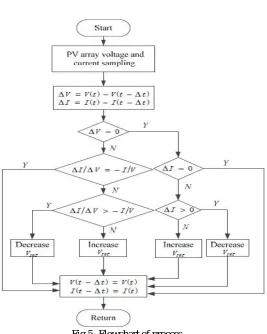
IV. PROPOSED METHODOLOGY FOR MPPT OPTIMISATION
Fig 5- Flowchart of process
In the classical control theory, the differential signal for a given signal is obtained by the differential element that has a small time constant, but it has amplificatory effect on the noise, it is not suitable for obtaining the differential signal in engineering application. The fast tracking differentiator (TD)overcomes this drawback, which on the one hand can quickly track the input signal and on the other hand can givethe differential signal of it, the general form of the tracking differentiator is given by:
wherev t is the input signal, x1 and x2 are tracking output and differential output, respectively, r determine the tracking speed. In this way, we can use two tracking differentiators to get differential signals of current and voltage, so that we can getdy/dx.With the above process, I/V and dI/dV are obtained, an errorsignal is generatedgiven by: e = I/V +
dI/dV.
Fig 6- Structure of linear active disturbance rejection controller for second order system
V. SIMULATION RESULTS
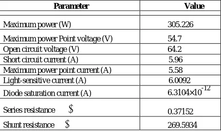
To investigate the performance of the proposed method, a whole photovoltaic power generation system is modeled in the Matlab/Simulink. The system is composed of a PV panel, a boost DC-DC converter, a MPPT controller and a load. The photovoltaic model which is used in this paper and its electrical characteristics in conditions that radiation is 1000 W/m2 and temperature is 25oC are shown in Table 1 derived from NREL manual.
TABLE I
ELECTRICAL CHARACTERISTICS OF USED MODEL
Parameter Value
Maximum power (W) 305.226
Maximum power Point voltage (V) 54.7
Open circuit voltage (V) 64.2
Short circuit current (A) 5.96 Maximum power point current (A) 5.58 Light-sensitive current (A) 6.0092
Diode saturation current (A) 6.3104×10⁻¹²
Series resistance Ω 0.37152
Shunt resistance Ω 269.5934
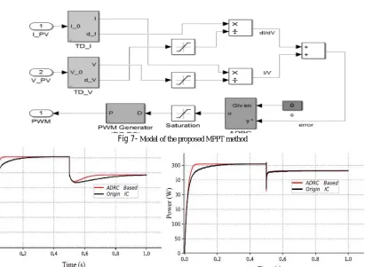
Fig 7- Model of the proposed MPPT method
Fig 8- Simulation results under two sets of conditions: (a) fixed radiation and temperature changes (b) fixed temperature and radiation changes
VI. CONCLUSIONS
ADRC can be used to solve the largest photovoltaic power power with the problem. Can effectively resist external interference, to improve the efficiency of solar power. Its greatest feature is that the system has strong internal and external interference suppression, showing a good robustness and adaptability. This paper, the disturbance rejection control introduced into the solar photovoltaic system, the load current and supply voltage from outside influence as a system of unknown factors such as interference and its dynamic compensation, eliminating the need for complex system testing MPPT optimization process has a strong real-time, simplifies the control process of the whole system. At the same time, the design parameters of ADRC parameters within the system.Parameter selection can be obtained in a larger context, the control system structure is relatively simple and easy to implement.
REFERENCES
[1] XU Honghua, “The study on development of PV technology in China,”Power System Technology, vol. 31, no. 20, pp.77-81, 2007 (in Chinese). [2] ZHOU Dejia, ZHAO Zhengming, YUAN Liqiang, et al. “Implementation of a photovoltaic grid-connected system based on improved
maximum power point tracking,” Proceedings of the CSEE, vol. 28, no. 31, pp.94- 100, 2008 (in Chinese).
[3] Villalva M G, Gazoli J R, Filho E R. “Comprehensive approach to modeling and simulation of photovoltaic arrays,” IEEE Transaction
onPower Electronics, vol. 24, no. 5, pp.1198-1208, 2009.
[4] Xiao W, Dunford W G, Capel A. “A novel modeling method for photovoltaic cells,” 2004 35th Annual IEEE Power Electronics [5] Specialists Conference, vol. 3, pp.1950-1956, 2004.
[8] [6] Heydari-doostabad H, Keypour R, Khalghani M R, Khooban M H. “Anew approach in MPPT for photovoltaic array based on extremum [9] seeking control under uniform and non-uniform irradiances,” SolarEnergy, vol. 94, pp.28-36, 2013.
[10] [7] Zhao J, Zhou X, Ma Y, Liu W. “A novel maximum power point trackingstrategy based on optimal voltage control for photovoltaic systems undervariable environmental conditions,” Solar Energy, vol. 122, pp.640-649,2015.
[11] [8] De Brito M A G, Sampaio L P, Luigi G, E Melo G A, Canesin C A.“Comparative analysis of MPPT techniques for PV applications,” CleanElectrical Power (ICCEP), 2011 International Conference on. IEEE,pp.99-104,2011.
[12] [9] Saravana S D. “Modeling and simulation of incremental conductanceMPPT algorithm for photovoltaic applications,” International Journal
ofScientific Engineering and Technology, pp.2277-1581, 2013.
[13] [10] Han J. “From PID to active disturbance rejection control,” IEEEtransactions on Industrial Electronics, vol. 56, no. 3, pp.900-906, 2009.
[14] [11] Esram T, Chapman P L. “Comparison of photovoltaic array maximumpower point tracking techniques,” IEEE Transactions on energy
[15] conversion, vol. 22, no. 2, pp.439-449, 2007.
[16] [12] Gao Z. “Scaling and bandwidth-parameterization based controllertuning,” Proceedings of the American control conference. vol. 6, [17] pp.4989-4996, 2006.