International Journal of Emerging Technology and Advanced Engineering
Website: www.ijetae.com (ISSN 2250-2459,ISO 9001:2008 Certified Journal, Volume 4, Issue 8, August 2014)
297
Forging Process Control by Additional Rocket Force
Dimitar Karastoyanov
1, Vladimir Kotev
2, Todor Penchev
31Institute of Information and Communication Technologies (IICT) – Bulgarian Academy of Sciences (BAS) 2,3IICT – BAS, Acad. George Bonchev str., bl. 2, Sofia 1113, Bulgaria
Abstract— Technological processes such as forging, die forging, and pile driving are realized as a result of a collision between two bodies. After the impact the bodies’ energy transforms to plastic or elastic deformations of the colliding bodies. This paper studies both theoretically and experimentally the influence of impact parameters such as forces, accelerations, velocities, time and energy on deformation and shape forming of parts achieved by forging with additional controlled force applied during the impact. Two experimental set-up (machines) for generating of additional force in forging with hammer have been developed and tested. The first one is a forging hummer with attached rocket engine (IRE). IRE was developed in Bulgaria and certified in Russia. Rocket engine is applicable for propelling hammering machines – a high-speed forging hammer and a diesel hammer for pile fixing. Possibilities for broadening the technological capabilities of these machines by the use of IRE are also shown. The second forging laboratory set-up uses compressed air to generate additional force as well as to control the impact. The introduction of additional force in forging leads to decreasing of the coefficient of restitution. In order to control the working conditions in forging the dynamics of the impact process is analysed. Many experiments on different parts and materials are done by different set of forging parameters using controlled impact. An increase of the specimen deformation was obtained compared to the common free-fall impact deformation as well as a decrease of the rebound to zero (we called that a sticking impact). Our theoretical results are confirmed by experiments. The obtained theoretical and experimental results show that controlled impact enhances forging process.
Keywords—Forging, Control of Impact, Deformations, Experiments.
I. INTRODUCTION
Forging is a bulk deformation process in which the workpiece is compressed between two opposing dies so that the die shapes are imparted to the workpiece. Bulk deformation processes involve large amount of plastic deformation [1], [2]. The cross-section of workpiece changes without volume change [1], [2]. The temperature in forging has significant influence on metal forming processes [1]-[3]. Cold working is metal forming performed at room temperature [1].
The cold working forging processes has the following advantages: better accuracy, better surface finish, high strength and hardness of the part, no heating is required [1], [2]. The main disadvantages are higher forces and power limitations to the amount of forming, additional annealing for some material is required, and some materials are not capable of cold working [1], [2]. In order to manufacture parts with high geometrical accuracy by forging and pile driving hammers a cold working process can be used [1]-[6]. The speed of the falling parts of these machines is 5-7 m/s. For forging of special alloy forgings and forgings of complex shape, high-speed gas forging hammers are used with speed of the falling parts of 16–20 m/s [1]-[6].
Today, forging is a major world-wide industry that has significantly contributed to humanity's development. Typical parts manufactured by forging are bolts, rivets, connecting rods, tube shafts, coins, gears, hand tools, structural components of machinery and aircraft and etc. [1]-[4]. Forging processes are achieved by the following machines: hydraulic press, mechanical press with an eccentric or pneumatic drive, the eccentric shaft can be replaced by a crankshaft to give the up-and-down motion to the ram, knuckle-joint press, screw press, and gravity drop hammer [1], [2]. These machines have some mechanical restrictions like energy, load and stroke limitation [1], [2].
International Journal of Emerging Technology and Advanced Engineering
Website: www.ijetae.com (ISSN 2250-2459,ISO 9001:2008 Certified Journal, Volume 4, Issue 8, August 2014)
298
With increase of the additional force we can achieve value at which to obtain impact without rebound, which is called in [4], [5] sticking impact. The possibility for altering the parameters of the impact at the beginning of impact between colliding bodies gives us grounds to confirm the term controlled impact [5], [6]. Further studies are needed to explore the possibility of reducing the rebound in the technological impact processes such as forging, die forging, pile driving and high velocity briquetting of waste and powder materials.
The aim of this paper is to study the influence of force, velocity, energy transformation, and time of impact on deformation of parts achieved by addition force generated by rocket engine. We try to control and optimize the forging process conditions material.
II. FORGING HAMMER DRIVEN BY ROCKET ENGINE
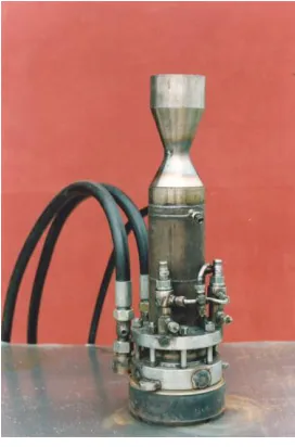
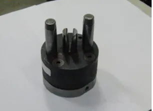
Generally, pneumatic and hydraulic driven hammers are used for hot die forging. In these types of machines the ram or their falling parts generates forces from 0.5 to 40 tons [1]-[4],[13]. A novel type of hammer driven by rocket engine (HDRE) for impact plastic deformation has been developed (Figure 1a) [2],[3],[13]. On the Figure 1b is shown industrial rocket engine (IRE) used in this hammer. This type of engine is suitable for propelling impact industrial machines – hot forging hammers, briquetting and pile fixing machines. The possibility of controlling this engine’s parameters (effort, speed, time of action, and time of switching on and off) in broad limits increases substantially the technological capabilities of those machines. From Figure 1 it can be seen that the developed HDRE has relatively simple design and performance. This circumstance makes it more reliable and user-friendly than standard hammers. This HDRE was developed in Bulgaria and certified in Russia. The die forging hammer shown on Figure 1 has a falling part with mass of 220 kg. In comparison with conventional hammers it is able to generate higher deformation force than conventional because of its high deformation speed. Approximately, HDRE hammer with 220kg falling part could generate the same deformation force as conventional hammer with falling part with mass 2 tons [2]-[4],[13],[14]. It could generate impact velocities in the range from 6 m/s up to 25 m/s. The magnitude of impact velocity depends on the amount of fuel (kerosene) supply and time performance duration of the hammer. Generally, the impact speeds of the standard hydraulic and pneumatic hammers are in the range of 5–7 m/s. Therefore, the HDRE can work with impact velocities like the standard types of hammers.
Figure1a. View of forging hammer driven by rocket engine (HDRE).
Figure 1b. Industrial rocket engine (IRE).
[image:2.612.375.511.351.557.2]International Journal of Emerging Technology and Advanced Engineering
Website: www.ijetae.com (ISSN 2250-2459,ISO 9001:2008 Certified Journal, Volume 4, Issue 8, August 2014)
299
It can be achieved impact without rebound under certain conditions. This phenomenon is called sticking impact [4]-[6]. More information about the experiments made by HDRE as well as its technical properties could be found in [2]-[4],[13],[14].
III. SET-UP FOR CONTROLLED IMPACT
A. Set-up Description and Impact
The free impact is an uncontrolled process [1]-[6], [8],[11]. It generates a rebound of the colliding bodies. The rebound energy (Erb) is part of the impact energy (Ei). The decrease of the both rebound and rebound energy leads to the increase of the efficiency of the impact machines and increases the tool’s life [1]-[7]. A laboratory set-up for
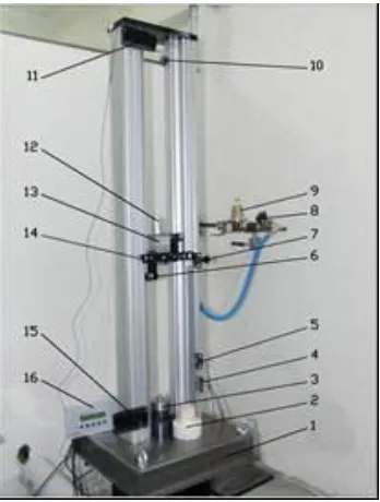
[image:3.612.321.549.413.623.2]exploration of controlled impact was created in a laboratory at the Technical University of Sofia-Bulgaria [5]-[7],[13],[14]. This laboratory set-up for controlled impact utilizing cold rocket engine driven by compressed air is shown on the Figure 2 [4],[7],[14]. It works with pressurized air that can be continuously changed in the limits of 5 to 35 bars. In particular the attached to the falling part cold rocket engine is driven compressed air instead by kerosene. The maximum drop height is 1.1 m, and the impact speed is between 1 and 8,2 m/s.
Figure 2. The laboratory set up for controlled impact.
The components of the depicted set-up on the Figure 2 are: 1 – base plate with a mass of 235 kg; 2 – lower fixed body for elastic impact; 3 – lower fixed tool for plastic impact; 4 – induction speed sensors; 5 – air on/off induction sensor; 6 – guides for the falling part; 7 – trigger mechanism; 8 - electro-magnetic valve; 9 – air pressure control valve; 10 - air ‘On’ sensor; 11 – receiver of the light sensor for speed; 12 – cold rocket engine; 13 – 6,17 kg mass falling part (ram); 14 – plate for activation of sensors 4, 5 and 11; 15 – light speed sensor emitter; 16 – electronic control board. Also, the experimental set-us is equipped with computer unit and control software. A Casio Exlim EX-F1, 1200 fps camera was used to film the collision and rebound [6],[7],[14].
[image:3.612.82.256.428.658.2]The experimental set-up from Figure 2 allows four regimes of operation to be set by its control unit. These four regimes are given schematically on the Figure 3b-d. The first mode is free fall of the ram and applying of additional force (Fad) at the time of impact (Figure 3b). The second mode is fall with acceleration by a rocket engine (Figure 3c). The next mode is fall with acceleration (a) generated by rocket engine and applying of an additional force. The last regime is the free fall (Figure 3d).
Figure 3. The studied cases of impact in forging. 1-base plate; 2- lower fixed body for elastic impact; 3-ram, 4-cold
rocked engine, 5- work piece, and h=1.1 m.
e)
a
)
b)
c)
d)
International Journal of Emerging Technology and Advanced Engineering
Website: www.ijetae.com (ISSN 2250-2459,ISO 9001:2008 Certified Journal, Volume 4, Issue 8, August 2014)
300
The velocities of the colliding bodies in impact are changing very fast for a very short period of time in a range of few milliseconds or nanoseconds [2], [8-12]. During the impact period very high forces are acting on the colliding bodies. These forces lead to body’s deformations and energy transformation [2], [9]-[12]. To control the impact between bodies the dynamics of impact has to be studied [9]-[11]. The main problems in impact dynamics are to find bodies accelerations and velocities after impact with given ones before impact as well as the hit impulses during the impact [9], [10].
In our theoretical and experimental study the following four cases of impact (Figure 3) are considered:
1. Free fall of the ram and additional force (Fad) at the time of impact. In this case of the controlled impact the maximum speed is V1=4.5 m/s;
2. Fall with acceleration by a rocket engine without Fad in the time of impact (free fall with maximum V1 = 8.5 m/s);
3. Fall with acceleration generated by rocket engine and Fad in the time of impact (controlled impact with maximum speed V1 = 8.5 m/s );
4. Free fall with maximum speed V1 = 4.5 m/s.
B. Dynamics of Impact in Forging Process
The dynamics of two colliding bodies which have a common normal passing through their mass centres (Figures 2 and 3) are considered. These two bodies represent the dies, workpiece and hammer’s ram, respectively. A straight line perpendicular to the plane of contact of two colliding bodies is called the line of impact. If the centres of gravity of the two bodies lie on the line of contact, the impact is called central or direct impact, in any other case, eccentric impact [9], [10]. We assume that the mass of base plate is larger than the mass of the ram. The dynamics of this phenomenon can be described by equation (1) and (2).
S mv
mu , (1)
. dt F = S
where:m = 6,17 kg is a mass of the ram, u is the speed after impact, v is the speed before impact,
S is the impact impulse. This integral represents the forces acting during the impact.
After collision, the bodies continue to move with changed velocities of v1 and v2. Since the contact forces on
one body are equal to and opposite the contact forces on the other, the sum of the linear momenta of the two bodies is conserved. In collinear impact the equation (1) can be written in the following form
.
)
v
--k(v
=
u
-u
v
m
+
v
m
=
u
m
+
u
m
2 1 2 1 2 2 1 1 2 2 1 1 (2)where: k is the coefficient of restitution after a collision. The value of k depends of the shape and material properties of the colliding bodies [4]-[7], [9]-[13]. In elastic impact, the coefficient of restitution is unity and there is no energy loss. A coefficient of restitution of zero indicates perfectly inelastic or plastic impact, where there is no separation of the bodies after collision and the energy loss is a maximum. In oblique impact, the coefficient of restitution applies only to those components of velocity along the line of impact or normal to the plane of impact [6], [9]-[11]. The velocity of base plate m2 is unchanged for
all practical purposes during impact and k = u1/v1. Moreover k could be express like
. h h =
k reb (3)
Where: h is a ram dropped from a height h upon the workpiece or a base plate and rebounding to a height hreb.
The both colliding bodies the ram and plate base respectively, interact each other by internal impulse
. 1 1 2 1 2 1 2 1 v m + m m m k) + ( = S =
S (4)
The waste of the kinetic energy (T) during the impact is
1
.2 1 T
- 1 2 2
2 2 1 2 1 1
2 k v v
m + m m m =
T (5)
Generally, the equations from (1) to (5) describe dynamics of plastic working of metals achieved by hammers.
C. Energy and Deformations in Forging Process
Forging is a multi-step impact process. Several impacts are carried out to achieve a degree of deformation ɛmaxof a
specimen with maximum height of deformation H0
International Journal of Emerging Technology and Advanced Engineering
Website: www.ijetae.com (ISSN 2250-2459,ISO 9001:2008 Certified Journal, Volume 4, Issue 8, August 2014)
301
The relation between the maximal deformation of the specimen and its maximal high is ɛmax = (H0
-Hmin/H0).100%≈35%. After each i-th impact (i=1,2,…,n)
the height Hi is measured and the following parameters:
relative deformation - ɛi, total deformation - ɛΣ, impact
(kinetic) energy Ti , total energy EΣ, specific imapact
energy, total impact energy after each impact are defined. These parameters are determined by the equations from (6) to (11) [9]-[14].
The relative deformation (ɛ) by each i-th impact is
100 . 0 0
H H H
= i
i
% . (6)
The total deformation (ɛ) by each i-th impact is
i n
i
1
%. (7)
The kinetic energy (Ti) after each i-th impact is
2 2
i i
mV
T
J.
(8)Total energy (EΣ) after each i-th impact is
i n
i
E
E
1
J. (9)
The specific impact energy after each i-th impact is
i i s
T
E , J/sm
3, (10)
where is volume of the workpiece.
0 2 0.
. 785 .
0 D H
sm3.
The total specific impact energy after each i-th impact is
i s n
i
s E
E ,
1
,
J/sm3. (11)
where: Vi is the impact velocity m/s.
IV. CONTROLLED FORGING -EXPERIMENTS
D. Die Forging Deformations
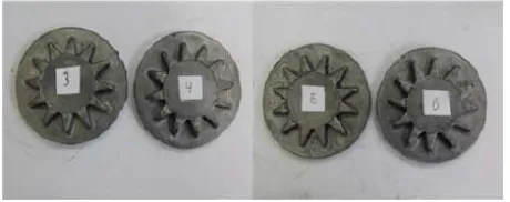
[image:5.612.338.556.245.354.2]Gear manufacturing experiments by controlled forging process is made. In the Figure 4a is shown a draw of gear type forging and on the Figure 4b is shown the die for this forging. Lead billets with diameter D=36 mm, H=46 mm (H/D = 1.27) and 530,70 gr. mass are used. The mass of the falling part is m=35,47 kg.
Figure 4. Draw of the gear type forging (a) and die (b).
The experiments are conducted at the deformation regimes 2 (Figure 3.c.) and 3 (Figure 3.d.) or fall with acceleration by a rocket engine without Fad, and fall with acceleration generated by rocket engine and Fad respectively. Moreover, the results of the both experiments are compared and analysed. Successive blows on the billet are applied and after each blow the forging is took out and the degree of filling of the die is assessed. The total energy consumed in each impact regime is determined as well as the number of the blows of die filling is counted. Figure 5 shows the obtained gears by simple (number 4 and 6) and controlled forging (number 3 and 5).
[image:5.612.330.560.517.608.2]International Journal of Emerging Technology and Advanced Engineering
Website: www.ijetae.com (ISSN 2250-2459,ISO 9001:2008 Certified Journal, Volume 4, Issue 8, August 2014)
302
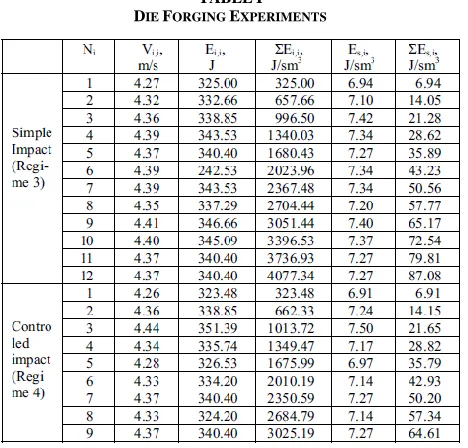
The obtained from the experiments data is shown on the Table 1.
TABLEI
DIE FORGING EXPERIMENTS
The obtained results in Table 1 shows the total energy ΣEs,i in a forging with simple impact is ΣEi,i=4077.34J
(after 12 impacts) to obtain good quality part in forging. In combined controlled impact the necessarily energy is ΣEi,i=3025.19J (after 9 impacts). The total energy
difference is ΔΣEi,i=1052,15J. The energy consumption of
combined impact die forging is with 25,8% less than forging achieved by simple impact. Therefore, hammer with 25,8% less impact energy than conventional hammers with simple impact can be used in hot die forging. For example the impact energy of simple blow hammer with m=2 tons falling part (ram) and impact velocity Vi=4.5 m/s is
20250 2
5 , 4 .
2000 2
=
Es J (12)
At the rocket engine propelled hammer the energy reducing is 25,8%. Therefore, the total energy of 15025.5J in combined hammer will be equivalent to mass of the ram
484 , 1 1484 2
25 , 20 . 5 ,
15025 =m m kg tons (13)
From equation (13) follows that in combined impact die forging with same impact speed of 4,5 m/s can be used a hammer with ram mass of 1.484 ton, i.e. to work with small standard hammer for hot die forging with ram mass of 1.5 ton. This result is unaffected from the impact velocity [14]. The obtained results show that rocket engine propelled hammer with smaller rams than standard ones can be used in die forging production practice. In addition the obtained degree of deformation by combined impact is greater than obtained by simple impact. The magnitude of this difference depends on many factors but the most important is the thrust force of the rocket engine generated by compressed air.
E. Deformation by upsetting
In these experiments the controlled impact set-up is set on again on regimes 2 (Figure 3.c.) and 3 (Figure 3.d.) or fall with acceleration by a rocket engine without Fad, and fall with acceleration generated by rocket engine and Fad respectively, and h=1m. Lead specimens (Figure 6.a) with D0=60mm, H0=72mm, equal volume K = 4.786 sm3 and
H0/D0 = 1.2; 1.5; 1.8 are used for the experiments. The
[image:6.612.53.287.170.394.2]falling part mass is m = 6.17 kg, and its impact velocity Vi = (2,90 - 8,80) ± 2 %, m/s. The upsetting is realized by maximum friction on contact surfaces. The deformed specimens in forging are shown on the Figure 6. The experimental data is shown in Table 2.
[image:6.612.339.545.449.618.2]International Journal of Emerging Technology and Advanced Engineering
Website: www.ijetae.com (ISSN 2250-2459,ISO 9001:2008 Certified Journal, Volume 4, Issue 8, August 2014)
303
[image:7.612.51.298.169.387.2]The right specimen on Figure 6 is deformed with controlled impacts.
TABLE II Forging Experiments
The obtained results in Table II show that with increase the number of strokes increases the difference Δε. There is a relation between impact velocities and the minimal specific impact energy. It is seen from the Table II that at impact velocity Vi=4,5 m/s the (Es)min = 4,95 J/sm3 and at Vi=7,2 m/s the (Es)min = 3,5 J/sm3. Therefore, (Es)min depends on the both impact velocity Vi and additional (thrust) force Fad generated by rocket engine in a case of controlled impact [14]. It is found from the conducted upsetting experiments with lead specimen with H0/D0 = 1.2
that relative degree of deformation Δεavg is 3.59%. This
difference means that the average deformation by upsetting combine impact is 10,3% more than upsetting by simple impact achieved in regime 2 (Figure 3.c.).
F. Impact, Rebound Force and Coefficient of Restitution In Forging
As we mentioned above the coefficient of restitution (k) is one of the basic parameters describing impact processes between hard bodies. It is defined by the equation (3). The energy for elastic deformation defines the value of the rebound after impact. If the bodies are ideally elastic the impact energy is entirely spent to generate a rebound and the coefficient is k=1 (no friction impact). If the bodies are ideally plastic the whole energy is spent on plastic deformation and k=0.
Therefore the coefficient of restitution which at impact changes between the values 0 ≤ k ≤ 1 is an indicator of the energy efficiency of the impact technological processes [9]-[11]. For example, in forging, the lesser the rebound of the impact tool, the greater part of the hit energy is used for plastic deformation of the blank, i.e. the coefficient of efficiency of the impact is greater [1], [4].
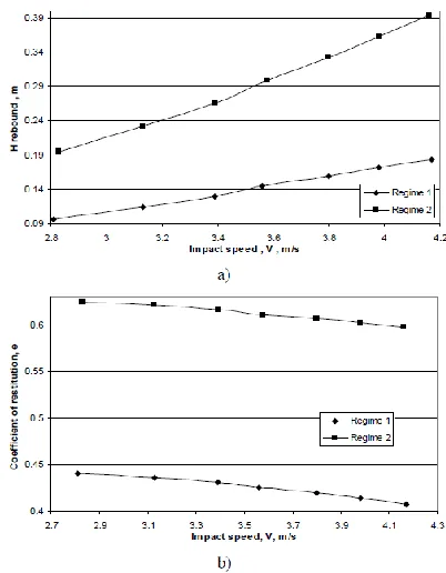
In order to reduce rebound in forging many experiments have been done with the experimental set-up for the controlled impact. It is found out that using of an additional force during the impact decreases rebound (Figure 7). In this section impact process of plastic part under the two of the regimes are studied. The first regime is free fall of the ram and additional force (Fad) (Figure 3.b) and the second one is free fall (Figure 3.e). The part’s material is polyamide Ertalon 66 SA, and its mechanical properties are elasticity module E = 345 MPa, dynamic strength 4,5 KJ/m2, and hardness HB=160 MPa. Variable fall height of the ram is set i.e. h = 0.5; 0.6; 0.7; 0.8; 0.9; 1.0; 1.1 m. Experiments are conducted with applying of Fad=216N at the period of impact. To generate Fad=216N the rocket engine was driven by air pressure of 30 bars [4]. The rebound force after a collision of two bodies with mass m1
and m2and a given k is calculated by equations (1), (2), and
(3). Rebound force of 1636N in free fall mode is calculated by equations (1)-(3).
[image:7.612.343.544.439.697.2]International Journal of Emerging Technology and Advanced Engineering
Website: www.ijetae.com (ISSN 2250-2459,ISO 9001:2008 Certified Journal, Volume 4, Issue 8, August 2014)
[image:8.612.353.528.136.405.2]304
Figure 7.a shows that by increasing the speed of impact, the difference in the rebound height for the two regimes also increases, i.e. the higher the impact speed, the bigger the effect of the additional force applied at the moment of impact Figure 7b shows that the decrease of k is averagely 30,47% if an additional force equal to 216N is used. The coefficient of restitution decreases if the velocity at impact is increased – Figure 7b. The decrease of rebound after the use of an additional force defines the decrease of the energy spent on elastic deformation of the dies as well as increase of the energy spent on plastic deformation for forging and die forging. That also leads to the decrease of the amplitude of tension/compression forces in the dies which improves their working conditions and they last longer.
G. Forging and Deformation by Reverse Extrusion – Experiment 1
The deformation in forging by reverse extrusion of the specimen is studied. The lead specimens shown on Figure 8 are used with H0=20 mm, D0=20 mm and 6.28 sm3 volume.
[image:8.612.53.284.393.456.2]The die diameter is 20 mm and punch diameter is 16 mm.
Figure 8. Slit specimens extruded by different impact energy.
The left side specimen in Figure 8 of each two is deformed by controlled impact and the right side specimen is deformed by free impact. The weight of the free dropped ram is 11.46 kg and falling height h = 0.965 m, 0.82 m, 0.74 m, 0.67 m, 0.47 m. The oil lubricant is used by deformation. After deformation the whole height s± 0.01 mm of the specimens is measured. Because of irregular extrusion heights smax, smin are measured and average height
hav = (smax + smin)/2 is calculated. After that the specimens
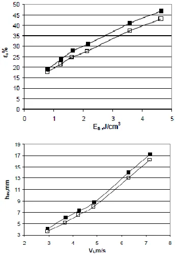
are slit – Figure 8. In Figure 9 the Vi – hav, Es – hav are
given in graphical form.
Figure 9. The variation of hav and Es. The case of free impact is
denoted by and the case of reverse extrusion in the
controlled impact is denoted by .
H. Forging and Deformation by Reverse Extrusion – Experiment 1I
[image:8.612.368.521.525.636.2]International Journal of Emerging Technology and Advanced Engineering
Website: www.ijetae.com (ISSN 2250-2459,ISO 9001:2008 Certified Journal, Volume 4, Issue 8, August 2014)
[image:9.612.92.246.133.252.2]305
Figure 10. Reverse extrusion – experiment II. Punch design (a) and deformed lead specimen (b).
After deformation the height h ± 0.01 mm of the deformed specimen part is measured. Because of irregular extrusion heights hmax, hmin are measured and average
height hav = (hmax + hmin)/2 is calculated. Then the specific
energy Es, and relative deformation ε are calculated by the equation (14)
100 . Q Q = p
i
%, (14)
where Q is the specimen volume sm3 and Qp is deformed
part of specimen volume sm3. The volume Qp is equal to Qp
= Q –Qc where c Qc is the volume of the cylindrical part of
the deformed specimen shown on the Figure 10.b.
Figure 11. Variation of the relative deformation ε (a) and the average height hav (b) with specific energy Es by reverse extrusion.
V. CONCLUSION
We study theoretically and experimentally two cases of forging by hammer. The first case is called free impact and the second is called controlled impact. The obtained results show that controlled impact enhanced forging process.
In die forging of a gear type forgings with the application of successive blows is found out deformation with combine controlled impact consumes 25,8% less energy than deformation achieved by simple impact. Therefore, in die forging manufacturing a rocket engine hammers driven by compressed air can be used. This type of hammer has smaller and lighter ram than standard hammers working with simple impact. The power of impact in combine controlled impact depends on the pleasure of compressed air driven the rocket engine of the hammer.
Impact and deformations of lead specimens are studied in simple and controlled forging. By controlled impact deformation 10,13% higher than simple impact are obtained. In this case the parameters of specimens were diameter 60 mm, H/D=1,2, Vi=4,5 m/s and additional force generated by rocket engine is Fad=230N. Significant difference in the relative degree of deformation between simple and controlled impact is obtained after reaching of a define value of the specific impact energy. This specific value is called minimum specific impact energy. It is influenced by the both impact velocity and the rocket engine trust force. Also, there is a relation between the rebound height hreb and coefficient of restitution k and
H0/D0 ratio and impact velocity Vi. When Vi increases hreb
and k decrease. By controlled impact upsetting at Vi ≥ 7.5 m/s hreb and k are equal zero (sticking impact), irrespective of H0/D0 value. By comparing the impact
[image:9.612.80.253.443.694.2]International Journal of Emerging Technology and Advanced Engineering
Website: www.ijetae.com (ISSN 2250-2459,ISO 9001:2008 Certified Journal, Volume 4, Issue 8, August 2014)
306
Further studies are needed to explore the possibility of reducing the rebound in the technological impact processes such as forging, die forging, pile driving and high velocity briquetting of waste and powder materials.
The derived mathematical model of the forging by hummer will help us to design experiments theoretically and to set working conditions properly. In order to establish a proper set of working conditions in forging we will study the impact energy transformation and piece deformation by thermo camera and 3D tomograph. To get structural information and impact influence 3D will be used
Acknowledgment
This work is supported by the project Advanced Computing for Innovation (AComIn), Grant 316087, funded by the FP7 Capacity Program (Research Potential of Convergence Regions initials).
REFERENCES
[1] Marinov, V. 2010 Manufacturing Processes for Metal Products. Kendall Hunt Publishing Company, Technology & Engineering. [2] Penchev T. and Karastoyanov, D. 2011. High speed industrial
hammer using rocket engine. In Proceedings of the XX-th ADP Conference, Sozopol, Bulgaria.
[3] Penchev T. and Karastoyanov D. 2012. New Industrial engine: priority and field of application. In Proceeding of the ICMAS 2012, Bucharest, Romania, published in Journal proceeding in manufacturing systems, 7, (4) pp:241-244.
[4] Penchev, T., Altaparmakov A. and Karastojanov, D. 2012. Experimental study on the possibilities to decrease the coefficient of restitution after impact. Applied Mechanics and Materials Vols. 217-219, pp: 1659-1662.
[5] Penchev, T., Karastoyanov D., and Monov V. 2013. Control system for controlled impact laboratory device. Third IEEE International Conference ICIST Information Science and Technology 2013, Yangzhou,Jiangsu, China, pp: 215-219.
[6] Penchev, T., Karastojanov, D., and Altaparmakov, I. 2013. Experimental study on controlled impact effect in plastic deformation process. Advanced Materials Research, 772, pp: 3-8. [7] Karastoyanov D., Kotev V. and Penchev T. 2014. Forging by rocket
driven hammer: dynamics and experiments. Advanced in Engineering Mechanics and Materials, pp: 174-177.
[8] Karastoyanov, D. 2010. Control of robots and other mechatronic systems, Academy Publ. House "Prof. Marin Drinov", (in Bulgarian) [9] Beer, F., Russell, E., Eisenberg, E., and Cornwell, Ph. 2009. Vector
mechanics for engineers: dynamics. McGraw-Hill
Science/Engineering/Math; 9 editions.
[10] Avallone, A., Baumeister, T. and Sadegh, A. 2007. MARK's Standard Handbook for Mechanical Engineers, 11th ed. New York: McGraw-Hill.
[11] Zhong-jin, W., Li-dong, C. 2008. Effect of material parameters on stress wave propagandation during fast upsetting, Transactions of Nonferous Materials Society of China, 2008, 18, 1189-1195. [12] Lucky, R. 1956. Automatic equalization for digital communication.
Bell Syst. Tech. J., vol. 44, no. 4, pp. 547-588.
[13] Penchev, T., Karastoyanov, D., New industrial engine-priority and field of application., International Conference ICMAS 2012, November 8-9 2012, Bucharest, Romania, published in Journal Proceedings In Manufacturing Systems, Vol. 7, Issue 4, 2012, ISSN 2067-9238, pp 241-244