5th International Scientific and Business Conference—Future Engineering 2019 ISBN: 978-1-60595-632-9
The Influence of Cutting Fluid and
Diamond-Like Carbon Coating on Cutting Tool Wear
Joanna Kowalczyk
1, Monika Madej
1, Krystian Milewski
2,
Łukasz Nowakowski
1and Dariusz Ozimina
1ABSTRACT
The aim of the research was to determine the effect of coolant on the wear of tools made of cemented carbides without a coating and with a diamond-like coating DLC type a-C:H and the quality of workpiece surface. The a-C:H coating was obtained by plasma-assisted chemical vapour deposition PACVD. Identification of the elements included in the cutting tool before and after turning was performed using a scanning electron microscope equipped with an EDS X-ray microanalyser. The face turning was carried out using a numerically controlled lathe. Turning were made without using cutting fluid ("dry") and using a non-toxic cutting fluid containing zinc aspartate. After turning, the wear of cutting tools was measured using a stereoscopic inspection microscope, and the surface texture of the workpieces was examined with an optical profilometer. The research discussed in this article contributed to the development of production thanks to the comparison of materials used for cutting tools for metalworking, as well as in the search for more and more durable cutting tools for extending durability of cutting tools, improving the quality of treated surfaces and reducing machining costs. During the machining process with the cutting fluid aspartate, layers of zinc compounds were formed, which reduced the coefficient of friction and tool wear.
Keywords: diamond-like carbon coating (DLC),cutting tools wear,friction, turning
_______________
1
Kielce University of Technology, Faculty of mechatronics and Mechanical Engineering, al. 1000-lecia PP 7, 35-31 Kielce, Poland
2
INTRODUCTION
One of the most frequently used methods of forming products is machining [1], which consists in removing material with the use of cutting tools [1-3]. The method is used in almost all production technologies [1]. During the machining process, tools are subjected to high loads arising during the chip formation process, as well as resistance to motion occurring between the tool and the workpiece. In addition, heat is generated during the deformation of materials and friction, which can cause the tool and chips to overheat and partial overheating of the machined workpieces. The contact surfaces are usually clean and very chemically active; therefore, complex physico-chemical processes take place on them [1, 4, 5]. That is why tools should be made of hard and durable materials that reduce the adhesion of the cutting tool material to the workpiece material.
Carbides are a common material used to produce cutting tools [6, 7]. Cemented carbides are multiphase composite materials manufactured by powder metallurgy consisting of one or more hard phases and a metallic bonding phase [8]. They are characterized by exceptionally high hardness, wear resistance, and excellent strength [6]. One of the drawbacks is their brittleness [6, 7].
In order to improve the mechanical, physico-chemical and technological properties of cemented carbide elements, surface layers can be applied to them. In recent years, there has been a rapid development of research on thin diamond-like carbon coatings applied using chemical vapour deposition (CVD) and physical vapour deposition (PVD) methods. They are widely used in various branches of industry due to their excellent tribological properties (low friction, anti-wear properties), stability and corrosion resistance, high hardness and thermal stability [9-14].
and energy consumption. Although the use of cutting fluids can improve tool durability, dry machining results in lower energy consumption and better surface finish.
Scientists have developed many techniques to reduce or eliminate the use of cutting fluids. This can be achieved by improving the properties of the cutting tool by, for example, applying a coating to it or developing new tool geometries. Advanced tool materials with a lower coefficient of friction, high hardness, good oxidation resistance, and high temperature resistance can significantly help in dry machining applications. This led to the introduction of advanced materials for the production of cutting tools such as regular boron nitride, cubic polycrystalline boron nitride, polycrystalline diamond, ceramic tools and others [17, 18].
Cutting fluids are also used to reduce tool wear and improve the surface quality of workpieces. They perform many directional functions, such as cooling, lubrication, a reduction in the friction coefficient, improvement in the surface condition, the transportation of chips from the machining zone, temporary protection of the product against corrosion, the extension of tool life, an improvement in the quality of manufactured products and the effectiveness of the machining process, a reduction in cutting force, and a reduction in workpiece deformation [19].
Mineral oil-based machining fluids are often used in machining operations. Statistics show that the costs of purchasing, preparing, maintaining, and removing cutting fluids account for a large share of the total production costs. In addition, global trends favour the environmental and health protection measures. They have contributed to scientific research towards safe/environmentally friendly production. Therefore, dry machining is becoming increasingly common, where the machining makes it possible to use a minimum amount of cutting fluids (Minimum Quantity Lubrication - MQL) as well as use non-toxic and biodegradable cutting fluids [18].
In this paper, the results of experimental studies carried out during dry turning and with a non-toxic cutting fluid containing zinc aspartate and tools made of carbide without and with a diamond-like carbon coating were compared.
TEST MATERIALS
Tools and Workpiece
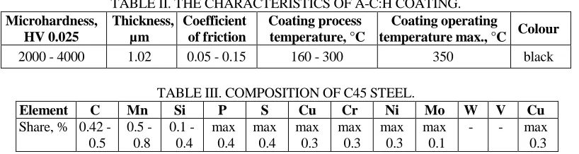
The following cemented carbide tools were used for facing: uncoated tools and tools with a a-C:H diamond-like carbon coating. The choice of these tools was dictated by the fact that carbide cutting tools are commonly used in machining. The chemical composition of SM25 cemented carbide is presented in Table I.
TABLE I. COMPOSITION OF SM25 CEMENTED CARBIDE.
Carbide/element WC TiC + TaC + NbC Co
TABLE II. THE CHARACTERISTICS OF A-C:H COATING. Microhardness, HV 0.025 Thickness, µm Coefficient of friction Coating process temperature, °C Coating operating
temperature max., °C Colour
2000 - 4000 1.02 0.05 - 0.15 160 - 300 350 black
TABLE III. COMPOSITION OF C45 STEEL.
Element C Mn Si P S Cu Cr Ni Mo W V Cu
Share, % 0.42 - 0.5 0.5 - 0.8 0.1 - 0.4 max 0.4 max 0.4 max 0.3 max 0.3 max 0.3 max 0.1
- - max
0.3
The a-C:H coating was obtained by plasma assisted chemical vapour deposition (PACVD). The PACVD process is a CVD process that is supported by glow discharge plasma. This method allows producing thin, hard surface layers, and layers with desired properties, e.g., protective, anticorrosive, and tribological [13]. Compared to CVD, the PACVD method is more effective in the initial phase of nucleation of the diamond structures. This process can produce a cleaner layer of high hardness, thermal conductivity, chemical inertia, as well as electrical and optical properties similar to diamond [20]. In the PACVD process, the pulsed glow discharge occurs at low pressure, resulting in higher internal energy, which allows the process temperature to be reduced from 300°C to 700°C. The process parameters must be carefully selected to match the substrate and coating materials to achieve good adhesion. There are many ways to achieve this, e.g., by changing the composition and partial pressure of the gas, as well as the glow discharge parameters. These control variables ultimately determine stoichiometry, the ratio of sp3 to sp2 bonds, the hardness of the layer, and the functional properties. When depositing ~1 μm/h, the PACVD layers have a dense column structure with a smooth surface that eliminates the need for final polishing [21].
The a-C:H coating has been applied to cemented carbide cutting tools. The properties of a diamond-like carbon coating are shown in Table II.
The workpiece was a 38 mm diameter shaft made of C45 steel. It is unalloyed, quality steel for quenching and tempering, difficult-to-weld, and its chemical composition is presented in Table III. C45steel is used for medium duty machine and device components. Products made of this steel can be surface hardened to a hardness of 50 - 60 HRC.
Machining Fluid
TABLE IV. PARAMETERS OF THE DEMINERALISED WATER AT 25°C.
pH Conductivity, mS/cm Maximum resistivity, MΩ—cm
5.0 - 7.2 5.5-10·10-5 (1.42 µS/cm) 18.2
TABLE V. PROPERTIES OF THE CUTTING FLUID CONTAINING ZINC ASPARTATE.
Colour Scent pH Density, g/cm3 Water solubility
from orange to red peculiar 9.2 - 9.7 1.20 - 1.25 soluble
This fluid contains, primarily the following:
Alkanolamine borate— 60%.
Biodegradable oligomer based on zinc poly(aspartic acid) (PASP)—30%.
Demineralised water.
The parameters of demineralised water are presented in Table IV.
Zinc poly-asparaginates are the basis for the biostability of the cutting fluid. The physical and chemical characteristics of the cutting fluid containing zinc aspartate are presented in Table V.
RESEARCH METHODOLOGY
The aim of the study was to compare uncoated cemented carbide cutting tools with cemented carbide cutting tools to which a a-C:H diamond-like carbon coating was applied.
Scanning Microscopy SEM/EDS
The elements forming the cutting tools made of cemented carbides with and without a-C:H coating were observed and identified with the use of a Phenom XL scanning electron microscope with an EDS microanalyser.
Turning Process
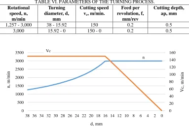
TABLE VI. PARAMETERS OF THE TURNING PROCESS. Rotational speed, n, m/min Turning diameter, d, mm Cutting speed vc, m/min.
Feed per revolution, f,
mm/rev
Cutting depth, ap, mm
1,257 - 3,000 38 - 15.92 150 0.2 0.5
3,000 15.92 - 0 150 - 0 0.2 0.5
n Vc 0 20 40 60 80 100 120 140 160 0 500 1000 1500 2000 2500 3000 3500
38 36 34 32 30 28 26 24 22 20 18 16 14 12 10 8 6 4 2 0
V c, m/ mi n n , m/ mi n d, mm
Figure 1. Dependence of rotational speed and cutting speed on the turning diameter for cemented carbide tools without and with a-C:H coating.
Facing was performed, during which 100 passages were made. After machining, the tool and the machined material were tested. The graph in Figure 1 shows the dependence of rotational speed and cutting speed on the turning diameter.
Geometric Structure of the Surface
The geometric structure of the surfaces of the elements after the turning process was analysed using a Leica DCM8 optical profilometer. In addition, an SX80 stereoscopic inspection microscope was used to observe the wear of the cutting tools after turning.
RESULTS AND DISCUSSIONS
Scanning Microscopy SEM/EDS
a) b)
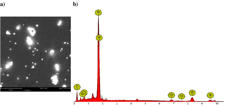
Figure 2. SEM image: a) surface morphology, b) characteristic spectrum (EDS) in a micro-area for a cemented carbide insert.
a) b)
Figure 3. SEM image: a) surface morphology, b) characteristic spectrum (EDS) in a micro-area for a diamond-coatedcemented carbide insert.
[image:7.612.103.489.329.513.2]The microstructure of the a-C:H coating surface (Figure 3a) shows that the coating has a fairly homogeneous surface, although lighter areas are visible. 1.44% cobalt content was identified in these areas. Tungsten content was also recorded at the level of 92.54% of mass. The remaining 6.02% was carbon. In the analysed micro-area, no carcinogenic elements such as titanium, tantalum, or niobium were identified.
Geometric Structure of the Surface
Photographs of cutting tools were taken using a SX80 stereoscopic inspection microscope, and with the use of the inspection microscope software, measurements of average VBB and maximum VBBmax widths of wear bands on the contact surface
were taken according to PN-ISO 3685 [22]. Figure 4 summarises the obtained values of VBB and VBBmax parameters.
The lowest mean value of the width of the band of abrasive wear on the contact surface (VBB) was observed for uncoated cemented carbide tools, both in case of dry
turning and with the use of a cutting fluid. In turn the smallest value of the maximum width of the band of abrasive wear on the contact surface (VBBmax) was
obtained after dry turning using cemented carbide tools with a-C:H coating (Figure 4b).
Comparing uncoated cemented carbide tools with a-C:H coated cemented carbide tools after dry turning, the tool diamond-like carbon coating was better. The VBB value was slightly higher, and the VBBmax value was almost 50% lower.
However, after turning using a cutting fluid, the consumption was about 3 times lower for uncoated cemented carbide tools than for those coated with a-C:H. A-C:H coated cemented carbide tools are more effective in dry turning than turning with the use of a cutting fluid. This is due to the self-lubricating property of the diamond-like carbon coating. Such tools do not require lubrication and can be used for dry machining. Uncoated cemented carbide tools, on the other hand, work better when used with cutting fluids. The use of a cutting fluid resulted in a reduction in the VBBmax value by about 1.6 times.
a)
[image:9.612.171.421.89.385.2]b)
Figure 4. Wear of the cutting tools made of cemented carbides after turning: a) without coating, b) with a-C:H coating.
a)
b)
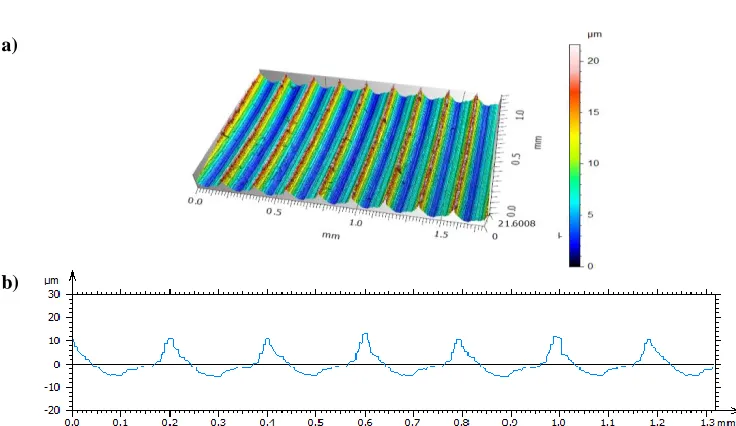
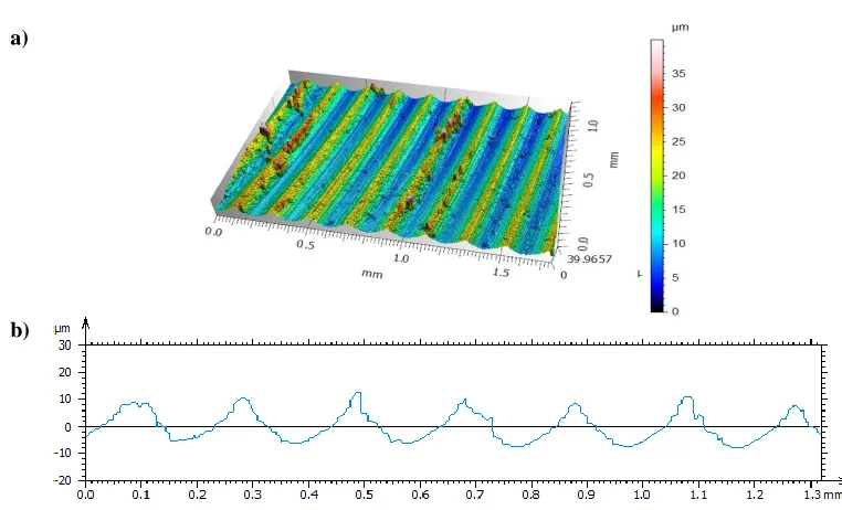
Figure 5. Surface texture of the edge of the workpiece after dry turning with a cemented carbide cutting tool: a) isometric view, b) primary profile.
Dry turning With cutting fluid containing zinc aspartate
[image:9.612.108.476.432.645.2]a)
[image:10.612.105.482.84.332.2]b)
Figure 6. Surface textureof the edge of the workpiece after dry turning with cemented carbide cutting tool with a-C:H coating:a) isometric view, b) primary profile.
a)
b)
[image:10.612.103.484.387.618.2]a)
[image:11.612.95.488.74.312.2]b)
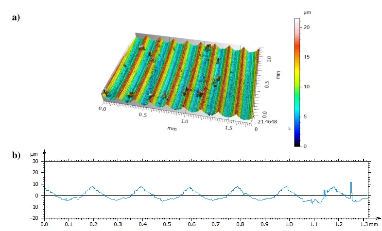
Figure 8. Surface texture of the edge of the workpiece after turning with cutting fluid containing zinc aspartate with a cemented carbide with a-C:H coating cutting tool:
a) isometric view, b) primary profile.
The carried-out analyses indicate that the lowest elevations and the shallowest recesses were formed on the workpiece after turning using a-C:H coated cemented carbide cutting tools with a cutting fluid containing zinc aspartate. The parallel tool passages (feed rate: 0.2 mm per revolution) are clearly visible on all workpieces. After dry machining and machining using a cutting fluid with an uncoated cemented carbide tool and after machining using a cutting fluid with an a-C:H coated cemented carbide tool, a few disturbances were observed. Peaks are clearly visible, and a few elevations could have been formed when the particles of the workpiece material transferred with the chip adhered to the workpiece.
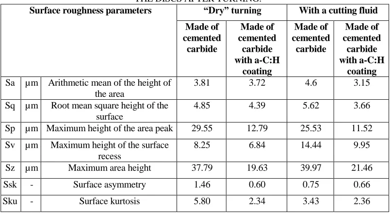
Table VII presents the parameters of the geometric structure of the surface of machined materials produced after dry turning and machining with a cutting fluid containing zinc aspartate.
When comparing the values of surface roughness parameters on the edge of the machined workpieces after the dry turning process and turning with a cutting fluid containing zinc aspartate, the following observations were made:
The lowest values of Sa, Sq, Sp and Sz were observed for the cemented carbide tool with a-C:H coating after turning with a cutting fluid.
The lowest Sv value was recorded for the cemented carbide tool after dry turning.
TABLE VII. SURFACE TEXTURE PARAMETERS OBTAINED FOR THE DISCS AFTER TURNING.
Surface roughness parameters “Dry” turning With a cutting fluid
Made of cemented carbide Made of cemented carbide with a-C:H coating Made of cemented carbide Made of cemented carbide with a-C:H coating
Sa µm Arithmetic mean of the height of the area
3.81 3.72 4.6 3.15
Sq µm Root mean square height of the surface
4.85 4.39 5.62 3.66
Sp µm Maximum height of the area peak 29.55 12.79 25.53 11.52
Sv µm Maximum height of the surface
recess
8.25 6.84 14.44 9.95
Sz µm Maximum area height 37.79 19.63 39.97 21.46
Ssk - Surface asymmetry 1.46 0.60 0.75 0.66
Sku - Surface kurtosis 5.80 2.34 3.43 2.36
The amplitude parameters of Ssk and Sku are sensitive to characteristic elevations and recesses as well as defects. A positive value of the Ssk parameter indicates elevations with sharpened geometry. Whereas, the Sku parameter (kurtosis) is a measure of the smoothness of the distribution curve of ordinates, which is also called the coefficient of concentration. For the normal ordinates distribution, Sku = 3.
Scanning Microscopy SEM/EDS
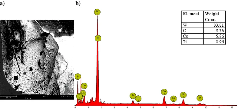
Figures 9 - 10 present SEM images of traces of tool wear after machining with cutting fluids and a point analysis of the elemental composition.
On tools made of cemented carbides without and with a-C:H coating applied at selected points on the build-up after turning with a cutting fluid, in addition to the elements coming from the tool material, an additional element coming from the workpiece, i.e. iron, was observed. A local transfer of material from the workpiece occurred. Thus, adhesion of the tool material to the workpiece material and the process of their selective transfer took place. Iron from the workpiece was not identified on a-C:H coated cemented carbide tools. The presence of elements such as titanium and cobalt from the substrate, i.e. cemented carbide, was observed.
a) b)
Figure 9. SEM analysis of the tool wear made of cemented carbides after turning with cutting fluid containing zinc aspartate: a) image of the wear track and b) X-ray energy spectrum.
a) b)
Figure 10. SEM analysis of the tool wear made of cemented carbides with a-C:H coating after turning with cutting fluid containing zinc aspartate: a) image of the wear track
and b) X-ray energy spectrum.
CONCLUSIONS
The tests carried out in this study are in line with current trends in the search for increasingly durable materials that will prolong use, ensure savings and eliminate downtime during production.
[image:13.612.101.494.346.531.2]surface (VBB) was obtained after facing using cemented carbide tools with a
cutting fluid containing zinc aspartate as well as dry machining. On the other hand, the lowest value of the maximum width of the band of abrasive wear on the contact surface (VBBmax) was obtained after dry turning with a-C:H coated
cemented carbide tools. Thus, due to its self-lubricating properties, the a-C:H coating perfectly fulfils its anti-wear function during dry machining.
The best parameters of the geometric structure of the surface, i.e. the lowest elevations Sz and the shallowest recesses Sv, were characterized by the details after turning using an a-C:H coated cemented carbide tool with a cutting fluid.
After turning, build-up was formed on the tools. In the case of machining using an uncoated cemented carbide tool with a cutting fluid, a local transfer of material from the workpiece occurred and layers of zinc compounds were formed. These layers contributed to the reduction of the coefficient of friction and wear of the tool.
REFERENCES
1. Ozimina, D., J. Kowalczyk, and M. Madej. 2016. “The impact of biodegradable cutting fluid on the tribological properties of the friction pairs”, Tribologia, 1:69–80.
2. Sheikh-Ahmad, J.Y. 2009. Machining of Polymer Composites. USA: Springer.
3. Olszak, W. 2009. Obróbka skrawaniem. Warszawa: WNT.
4. Dolinšek, S. and J. Kopač. 2006. “Mechanism and types of tool wear; particularities in advanced cutting materials”, Journal of Achievements in Materials and Manufacturing Engineering, 19(1):11–18.
5. Szczerek, M. 1997. Metodologiczne problemy systematyzacji eksperymentalnych badań tribologicznych, Radom: ITeE.
6. Liu, C.,N. Lin, Y.H. He, W.S. Liu, and Y.Z. Ma. 2018. “Influence of Micron WC Addition on the Microstructure and Mechanical Properties of Ultrafine WC–Co Cemented Carbides at the Elevated Temperature”, Journal of Superhard Materials, 40(1):40–46.
7. Wirtz, Ch., A. Dehmer, D. Trauth, P. Mattfeld, and F. Klocke. 2018. “Analysis of the grinding wheel wear in dependency of the cementedcarbide specification”, The International Journal of Advanced Manufacturing Technology, 99:747–754.
8. Lisovskii, A. F. and I.A. Gnatenko. 2018. “On the Formation of Intercarbide and Interface Surfaces in WC–Co Cemented Carbides”, Journal of Superhard Materials, 40(5):335–347. 9. Madej, M., J. Kowalczyk, and D. Ozimina. 2014. “The tribological properties of DLC coatings
lubricated with the biodegradable cutting fluid”, Tribologia, 5:101–112.
10.Folea, M., A. Roman, and N.B. Lupulescu. 2010. “An overview of DLC coatings on cutting tools performance”, Scientific papers. Academic journal of manufacturing engineering, 8(3):30–36.
11.Madej, M., K. Marczewska-Boczkowska, and D. Ozimina. 2014. “Effect of tungsten on the durability of diamond-like carbon coatings in the chemical industry”, Przemysł Chemiczny, 93(4):505–505.
12.Vengudusamy, B., A. Grafl, and K. Preinfalk. 2014. “Tribological properties of hydrogenated amorphous carbon under dry and lubricated conditions”, Diamond & Related Materials, 41:53–64.
14.Ozimina, D. 2013. The exploitation of tribological systems. Tom I. The importance of scientific instrument in operation buildings.. M48. Kielce: Ed. TU.
15.Sreejith, P. 2008. “Machining of 6061 aluminium alloy with MQL, dry and flooded lubricant conditions”, Materials Letters, 62:276–278.
16.Diniz, A.E. and R. Micaroni. 2002. “Cutting conditions for finish turning process aiming: the use of dry cutting”, International Journal of Machine Tools and Manufacture, 42(8):899–904. 17.Kustas, F.M., L.L. Fehrehnbacher, and R. Komanduri. 1997. “Nano coatings on cutting tools
for dry machining”, CIRP Annals - Manufacturing Technology, 46:39–42.
18.Gupta, K. 2019. Innovations in Manufacturing for Sustainability. Switzerland: Springer. 19.Smith, G.T. 2008. Cutting tool technology. Industrial handbook. London: Springer.
20.Jethanandani, R. 1997. “The Development and Application of Diamond Like Carbon Films”,
The Journal of The Minerals, Metals & Materials Society (TMS), 49(2):63–65.