The Effect of Laser Cutting Parameters on the Aerospace Structure
Panel of CFRP Composite Material
Md Saidin Wahab
1,a, Erween Abdul Rahim
2,b, Mohd Sukri Mustafa
3,cand Norzaina Abdul Rahman
4,d1,2,3,4
Advanced Materials and Manufacturing Center (AMMC), Universiti Tun Hussein Onn Malaysia, 86400 Parit Raja, Batu Pahat Johor, MALAYSIA
a
[email protected], [email protected], [email protected], [email protected]
Keywords: carbon fiber reinforced plastic,CFRP, Nd:YAG laser, Kerf geometry, HAZ
Abstract. This paper presents a research progress on the laser cutting characteristic of the carbon fiber reinforced plastic (CFRP) composites material for the aerospace structure panel. The CFRP is a high performance material and becomes one of the most important materials in the aerospace industry. The current machining techniques used by the aerospace composites manufacturing for cutting and trimming process have created some quality issues such as fiber pulled out and delamination. The use of laser cutting technology has shows promising advantages. However, the Laser cutting represents the interaction between laser beam and the CFRP composites, that produce heat affected zone (HAZ), kerf width and taper angle. Thermal damage is a direct consequence of the large difference in thermal properties of the carbon fiber and the polymer matrix. Therefore, the effect of laser cutting parameters such as pulse energy, pulse repetition rate, cutting speed and pulse duration need to be taken into consideration. A 300W Pulsed Nd:YAG laser machine was used in the experiment and successfully cut or trim the 1.5mm thickness of the CFRP component. The results also showed that the pulse energy and pulse repetition rate gave the most significant effect on the cutting characteristic in particular of kerf width, HAZ and taper angle.
Introduction
[image:1.595.58.495.566.700.2]Carbon fiber reinforced plastic (CFRP) is one of the most important materials for the next generation of lightweight layouts in aerospace applications [1]. For example, the Boeing 787 Dreamliner (Fig. 1) is about 50% composite material by weight, with much of that being carbon fiber laminates or sandwiches [2].CFRP composites materials are constructed by two materials, carbon fiber and polymer matrix that have significant different properties. The two materials are bond together to offer better mechanical properties [3]. The carbon fibers in the matrix were surrounded and held by polymer matrix [4], as shown in Fig. 2.
Fig.1 CFRP material in Boeing 787 [2] Fig. 2 CFRP material [3]
There are several machining techniques can be used to cut CFRP such as milling, trimming and drilling. However, fiber pulled out and delamination were the dominant quality issues for these machining process. Furthermore, the water jet cutting proces can be employed to cut the thin CFRP plate, but it is unsuitable when three-dimensional part needs to be fabricated. Therefore, laser cutting has a potential to replace water jet cutting for CFRP machining.
Laser cutting (Fig. 3) represents the interaction between laser beam and the CFRP composites, that produce heat affected zone (HAZ), kerf width and taper angle, as shown in Fig. 4. Thermal damage is a direct consequence of the large difference in thermal properties of the carbon fiber and the polymer matrix [5]. The heat-affected zone (HAZ) is the area of base material, which has had its microstructure and properties altered by heat intensive cutting operations. The heat from the cutting process and subsequent re-cooling causes this change in the area surrounding.Kerf width is a groove or notch made after cutting and taper angle is the base of the material become gradually narrower or thinner toward one end after cutting.
Fig. 3 Nd:YAG Laser cutting process on CFRP
The aim of this work is to study the effect of laser cutting characteristic behaviour on the CFRP laminated composites surfaces and layers. The use of pulsed Neodym-Ytttrium-Aluminum-Garnet (Nd:YAG) laser in cutting operation of CFRP was investigated. The high beam intensity and the focusing behaviour of pulsed Nd:YAG laser gives a smaller thermal, a narrow kerf and small HAZ which helps by obtaining good quality with proper parameter combinations [6].
Equipment, Materials and Experimental Procedures
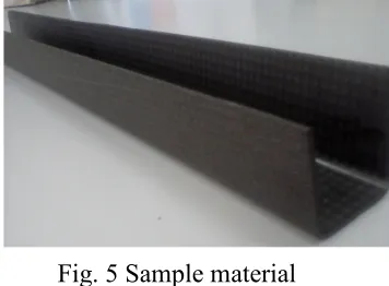
[image:2.595.312.507.190.329.2]Woven fabric carbon fiber reinforced plastic (CFRP) composites with a thickness of 1.5 mm received from Asian Composite Malaysia (ACM) Sdn. Bhd. were used this study (Fig. 5). A pre-preg laminates carbon fiber consists of twelve plies was made by non-self-adhesive with epoxy resin-impregnated graphite reinforcements, yarn and fabric (BMS9-8). The epoxy pre-impregnated by Type I graphite fiber unidirectional carbon fiber tapes and woven fabrics and curing under the temperature of (177˚C).
Table 1: Process parameters for laser cutting.
Fig. 5 Sample material
The pulsed Nd:YAGlaser machine (Model GSI- JK300HPS) was used and it works at the wavelength of 1064 nm and maximum nominal power of 300 W. The laser was operated in the TEM00 mode and the focused spot diameter was 0.1mm. The laser allows the selection of different
working parameters like the pump lamp voltage (V), the pulse frequency (F), and the pulse duration (D). The pulse energy and the pulse repetition rate play an important role during laser cutting, in
Fig. 4 Example of kerf geometry. Wt: top kerf width; Wb: bottom kerf width; Ta: taper angle; HAZ
Cutting Speed (mm/min) 30 Pulse Duration (ms) 0.5
Pulse Energy (J) 1.4, 1.8, 2.2 Pulse Repetition Rate (Hz) 35, 40, 45
Workpiece CFRP
Wt
Wb
HAZ
[image:2.595.84.247.196.318.2] [image:2.595.314.492.582.713.2]which, control the interaction between the laser beam and the material. In order to observe the effects of different parameters setting on machining characteristic, laser cutting trials were carried out adopting three different setting of pulse energy (pe) and pulse repetition rate (prr), as shown in Table 1. The different energy values were obtained by changing the pulse frequency and the lamp voltage. For each process condition, the cutting speed and pulse duration was constant at 30mm/min and 0.5ms respectively. In this study, to verify the cutting quality, the top and bottom kerf width, the taper angle and the HAZ extension were measured by optical microscopy.
Results and Discussion
Effect of Parameter on Kerf Width. The kerf width at top (Wt) and bottom (Wb) are two major
parameters to be assessed to evaluate the quality of a laser cutting surface. The kerf width gives an idea of the amount of overcut at the top and the bottom as well as the taper of the cut surface [4].
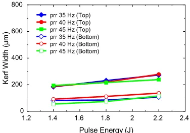
In Fig. 6, the result of the kerf width are presented. The top and the bottom kerf width decrease when the pulse repetition rate increase. Furthermore, top and bottom kerf width increase proportionally with the pulse energy, as shown in Fig. 7. Besides, the top kerf width for both parameters appears always larger than the bottom kerf width. This is due to the effect of energy losses which passes through the kerf, and some energy were absorbed by the laminated structure.
Fig. 6 Effect of pulse repetition rate (Hz) Fig. 7 Effect of pulse energy (J) on top on top and bottom kerf width. and bottom kerf width.
Effect of Parameter on HAZ. Factors that affecting the HAZ are pulse energy and pulse repetition rate. In laser machining, the cutting surfaces are generally covered by chars originating from the decomposition of the fibers and the matrix [7]. At high pulse repetition rate, the laser behaves like a continuous wave and the cutting surfaces has not enough time to cool down.
Higher pulse repetition rate of 45 Hz demonstrated a thinner HAZ layer, as compared to the other pulse repetition rate values, as shown in Fig. 8. However, the lower values of HAZ can be seen when the pulse energy of 1.4J was employed, as shown in Fig. 9. Both graphs show that the HAZ increase with the increasing pulse energy and pulse repetition rate. This is due to the fact that the HAZ is directly proportional to the pulse energy and pulse repetition rate.
34 36 38 40 42 44 46
0 200 400 600 800
Pulse Repetition Rate (Hz)
K e rf W id th ( µ m )
pe 1.4 J (Top) pe 1.8 J (Top) pe 2.2 J (Top) pe 1.4 J (Bottom) pe 1.8 J (Bottom) pe 2.2 J (Bottom)
1.2 1.4 1.6 1.8 2 2.2 2.4 0
200 400 600 800
Pulse Energy (J)
K e rf W id th ( µ m )
[image:3.595.309.497.344.476.2]Fig. 8 Effect of pulse energy (J) on HAZ Fig. 9 Effect of pulse repetition rate (Hz) on HAZ
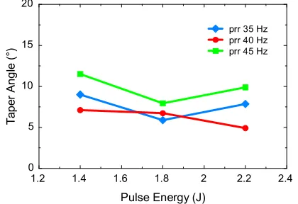
[image:4.595.317.521.90.253.2]Effect of Parameter on Taper. Fig. 10 and Fig. 11 show the effect of pulse repetition rate and pulse energy on taper angle respectively. The results demonstrated that the taper angle is very small, in ranges from 5˚ to 12˚ for both parameters. The taper is found to be minimum at the middle of pulse repetition rate and pulse energy. Meanwhile at the pulse energy of 1.8J, there are peculiarities in comparison with another value and same situation at pulse repetition rate 40Hz.
Fig. 10 Effect of pulse repetition rate (Hz) on taper angle
Fig. 11 Effect of pulse energy (J) on taper angle
Conclusions
In this experiment, performance of the pulsed Nd:YAG laser, when cutting the 1.5 mm thickness of CFRP laminates, are presented. On the basis of the results, the following main conclusions were drawn:
a) According to the experimental results, a pulsed Nd:YAG can be satisfactorily used to cut 1.5 mm thickness of CFRP plate with a cutting speed of about 30mm/min and pulse duration 0.5ms
b) Pulse energy and pulse repetition rate showed a significant effect on kerf width, HAZ and taper angle from the graph, which means both of these factors interrelated when a value is changed, then the response will also change
c) The HAZ and the kerf width depend on the energy release time dependence, a strategy to decrease the HAZ and the kerf width could involve the use of a very short interaction time. Therefore, high pulse energy gives high HAZ and high pulse repetition rate gives narrow kerf width
d) Taper is found to be minimum at the middle range of pulse repetition rate and pulse energy 1.2 1.4 1.6 1.8 2 2.2 2.4
0 200 400 600 800 1000 1200 1400 1600
Pulse Energy (J)
H A Z ( µ m )
prr 35 Hz prr 40 Hz prr 45 Hz
34 36 38 40 42 44 46
0 200 400 600 800 1000 1200 1400 1600
Pulse Repetition Rate (Hz)
H A Z ( µ m )
pe 1.4 J pe 1.8 J pe 2.2 J
34 36 38 40 42 44 46
0 5 10 15 20
Pulse Repetition Rate (Hz)
T a p e r A n g le ( °)
pe 1.4 J pe 1.8 J pe 2.2 J
1.2 1.4 1.6 1.8 2 2.2 2.4
0 5 10 15 20
Pulse Energy (J)
T a p e r A n g le ( °)
[image:4.595.312.522.367.511.2]Acknowledgement
The authors would like to acknowledge Universiti Tun Hussein Onn Malaysia and Ministry of Higher Education Malaysia for the (GIPS) and (MyMaster) financial support allocate for this project. In addition, the authors wish to thank Asian Composite Manufacturing Sdn. Bhd for supplying the materials used in the experiments.
References
[1] R. Weber, M. Hafner, A. Michalowski, T. Graf, Minimum Damage in CFRP Laser Processing. Physics Procedia 12 (2011) 302-307.
[2] Usage of carbon fiber, ‘aircraft and aerospace field’, Retrieved from http://www.carbonfiber.gr.jp/english/tanso/use01.html. 23 May 2012.
[3] Carbon Fiber Reinforced Polymer, retrieved from
http://en.wikipedia.org/wiki/Carbon-fiber-reinforced_polymer, 23 May 2012.
[4] Li, Z. L., Chu, P. L., Zheng, H. Y, Process development of laser machining of carbon fiber reinforced plastic. SIMTech technical reports.2009, 10.
[5] N. Pagano, C. Leone, V. Lopresto, Solid state Nd:YAG laser cutting of CFRP sheet: Influence of process parameters on kerf geometry and HAZ.
[6] J. Mathew, G. L. G., N. Ramakrishnan, N.K. Naik, Parametric studies on pulsed Nd:YAG laser cutting of carbon fiber reinforced plastic composites. J. Mater. Process Technol., 1999, 89–99: 198– 203.
The Effect of Laser Cutting Parameters on the Aerospace Structure Panel of CFRP Composite Material
![Fig.1 CFRP material in Boeing 787 [2]](https://thumb-us.123doks.com/thumbv2/123dok_us/8777853.902477/1.595.58.495.566.700/fig-cfrp-material-in-boeing.webp)