Study of Poles and Zeros Arrangement Method for
PID Controller on TCSC
Shamsul Aizam Zulkifli, Kok Boon Ching, Md Zarafi Ahmad, Rohaiza Hamdan, Nur Aliaa Ibrahim
Abstract -- TCSC seems to be one of the members of FACTS
family. It has many benefits in power quality problems including the increase of power and transient stability as well as in the sub-synchronous resonance mitigation. However, these advantages are highly depending on the controller used. This paper deals with Proportional Integral Derivative (PID) controller which is attempted to correct the error between a measured process variable and a desired set point by calculating and gives correct action that adjusts the response to the voltage sag or fault. Voltage sag is one of the most common power quality problems facing by industrial and commercial loads nowadays. The PID controller has been utilized to present the single phase Thyristor Controlled Series Capacitor (TCSC) with the new poles and zeros arrangement on the PID controller to investigate the effects of fault (during and post-fault) at the transmission line as well as at the distribution loads. As the results the new topology has solve the post fault effects on the distribution system.
Index terms –TCSC, PID controller, faults
I. INTRODUCTION
[image:1.612.73.272.541.638.2]P
OWER quality is an issue gaining significant interest for both electric utility and end-users. Most of the power quality issues are concerned with the voltage sags/fault when it occurred along the transmission line. The most affected load is at the distribution system. Thyristor Controlled Series Capacitor (TCSC) is an emerging technology that combines the conventional series capacitor with the Thyristor Controlled Reactors (TCR) in parallel [1-3]. The basic structure of the device is depicted in Fig. 1 [4].Fig.1. Basic structure of TCSC
S. Aizam, B.C. Kok, Md. Z. Ahmad, R.Hamdan, N. Aliaa are with the Department of Electrical Power Engineering, Faculty of Electrical and Electronic Engineering, Universiti Tun Hussein Onn Malaysia, Lock Bag 101, 86400 Parit Raja, Batu Pahat, Johor, Malaysia
(email: [email protected]).
The capacitor is inserted directly in series at the transmission line and the thyristor controlled inductor is mounted directly in parallel with the capacitor [5]. It is applied for the purpose of transient stability which able to solve unbalanced condition or voltage sag/fault on the transmission line with the suitable controller applied to it.
The possible use controllers are Proportional Integral (PI), Proportional Derivative (PD) and Proportional Integral Derivative (PID) controller. PID controller has been selected because of few reasons: (i) the settling time is faster than PI and PD controllers, (ii) less percent overshoot, (iii) faster time to steady state [6], and (iv) the response time is less than PI controller which is about 0.1sec [7] and this is an important parameter to voltage sag/fault. The function of poles and zeros arrangement is used to shift the initial poles from the right to the left of the complex diagram, in order to increase the stability of the system. This technique has been applied to the PID controller for fault analysis at the transmission lines level.
II. MODELLING OF TCSC
One of the functions of TSCS is in the voltage increment on the transmission line whenever there is a disturbance happened [8]. TCSC has the capability to provide a continuous variable capacitor by controlling the firing angle delay of the thyristor [9] and able in mitigating the sub-synchronous resonance that induced by the generator [8, 9].
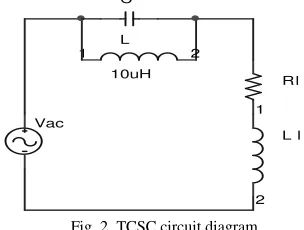
The advantage of using TCSC at the transmission line is the thyristor switching is allowed for unlimited number of operations. Fig. 2 shows the single line diagram of TCSC at the distribution network.
C
Vac L
10uH
1 2
Rl
L l
1
2
Fig. 2. TCSC circuit diagram
Components C and L representing the structure of TCSC and the distribution load is represented by RL and LL. The
[image:1.612.363.515.553.668.2]L L L L L L L L out in R L L S CL R S LCL s R SL CL R s LCL s V V + + + + + + + = ) ( 2 3 2 3
(1) [image:2.612.57.302.121.278.2]
The initial response of TSCS at the line is shown in Fig. 3 without any controller applied.
Fig.3: TCSC without PID response
It can be observed that the overshoot is about 15.5% and the settling time is at 0.0916s that is not suitable to response to a power quality time. The Zeigler Nicholas [6] method has been used to tune the Proportional Gain (Kp), Integral Gain (Ki) and Derivative Gain (Kd). These values have been found using the transfer function of the TCSC with several rules as referred to equation (2),
Kds S Ki
Kp+ + (2)
where Kp = 0.6(Kpu),
Ti = 0.5(p.u.),
Td = 0.125(p.u.),
Ki = Kp/Ti,
Kd = KpTd
The values of Kp. Ki and Kd have been determined by
[image:2.612.306.567.384.522.2]referring to the suggested method. PID controller is then connected to the device with the feedback loop after has done for the trial and error method [10] in order to determine the new poles and zeros arrangement.
Fig.4. New poles and zeros arrangement of PID controller at TCSC with feedback
The new arrangement of the TCSC with a feedback loop response is shown in Fig.4. It shows that the overshoot has been reduced to 0.0244% compared to Fig.3. The settling time has also been reduced to less then 0.005s which is suitable to response on fault condition.
This response is set when the root locus of the feedback response giving the new poles and zeros which is located at 1.0e+004 (7.9689, 0.0985 + 0.3758i, 0.0985 0.3758i, -0.2458, -0.0181) due to the technique applied. Table 1 shows the summary of the analysis for the response with or without new arrangement of PID.
Table 1: Summary of PID performances
Performance Overshoot
(%)
Peak Amplitude (p.u.)
Settling Time (s)
Without PID 15.5 1.15 0.092
With PID 0.0244 1 0.000986
III. SIMULATION RESULTS
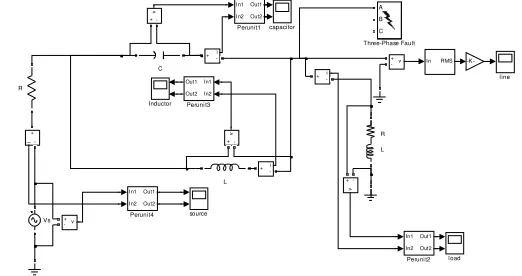
Fig.5 shows the layout of distribution system under the effect of voltage sag/fault condition. The main components of the distribution system consist of voltage supply, TCSC and load. The system has been simulated for 4 seconds with the fault applied during 1 to 2 sec.
Fig. 5. Distribution system under study
A. Distribution System without PID Controller
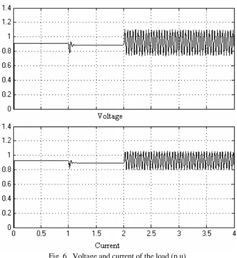
Fig. 6 shows the voltage and current of the system when fault occurred at distribution system. The load voltage is dropped from its nominal level to 0.88 p.u. during the fault time.
As can be seen from Fig. 6, the post-fault outputs show both signals consist of ripple voltage due to effect of TCSC where it is connected in series with the distribution loads. This TCSC has not been controlled by PID controller and it also due to the effect of the TCR of the TCSC.
source l oad l ine capacitor -K-i + -Vs v + -v + -v + -v + -v + -A B C A B C Three-Phase Fault R L R In1 In2 Out1 Out2 Perunit4 In1 In2 Out1 Out2 Peruni t3 In1 In2 Out1 Out2 Peruni t2 In1 In2 Out1 Out2 Perunit1 L Inductor i + -i + -i
+- In RMS
[image:2.612.52.297.559.731.2]Fig. 6. Voltage and current of the load (p.u)
The percentage of sag can be calculated where it drops to less then the normal value.
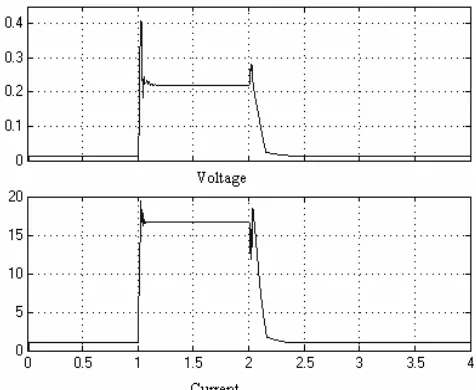
The most severe effect is on the TCSC components. Fig. 7 and Fig. 8 give the results of the output at the TCSC when the fault is applied and removed, respectively. During the fault time, both capacitor and inductor is working and thus the reactive power is injected and absorbed simultaneously.
This causes zero power transfer from the TCSC to the transmission line and will not mitigate the problem appeared at the distribution.
Fig. 7. Voltage (p.u) and current in capacitor (A)
Fig. 8. Voltage (p.u) and current inductor (A)
[image:3.612.54.299.48.314.2]
B. Operation of TCSC with new arrangement of poles and zeros on PID
Fig. 9 shows the PID control circuit that has been applied after the new poles and zeros arrangement to the TCSC with the proper firing angle block.
2 Out2 1
Out1
angle
156.15
alpha
Scope7 Scope6
R2D
Radians to Degrees
Pulse Generator2
Pulse Generator1
PID
PID Controller
Saturation
2 In2
[image:3.612.317.562.51.220.2]1 In1
Fig.9. PID control and firing angle block
[image:3.612.57.558.455.717.2]Fig. 10 shows that the voltage sag has been mitigated. The important results are on the post fault analysis. It shows that the ripple has been eliminated to give better quality supply to the load. This is due to the effect of the capacitor and inductor shown in Fig. 11 and Fig. 12, respectively.
Fig. 11 shows that when there is no fault, the capacitor will not inject any current. It means that the capacitor will only raise the voltage when there is a fault happened.
Fig. 12 shows the results on inductor where it will stop to inject current during the fault period because this function is taken by the capacitor. The inductor keeps maintained in approximately zero level as there is no voltage spike during the fault period or after the fault period. However, during the transaction period, the inductor absorbed the extra power from the transmission system. A small delay of time due to the parameters selected for the controller can be seen in the response.
Fig. 11. Voltage (p.u) and current for capacitor (A)
Fig.12. Voltage (p.u) and current in inductor (A)
IV. CONCLUSION
The power quality problem especially the post fault situation has been successfully mitigated by applying the new arrangement of poles and zeros into the PID controller. The PID controller is capable to handle fault and the ripple as well that induced by the capacitor and inductor of the TCSC. It also has been having better electric supply to the distribution although the TCSC is responded which injects capacitive current into the system when fault or disturbance occurs. As a conclusion, the new poles and zeros arrangement method hopefully can be implemented in other controllers in order to provide the best response to eliminate all the power quality problems.
IV. REFERENCES
[1] R. M. Mtahur and R. K.Varma (2000) “Thyristor- Based FACTS Controllers for Electrical Transmission System” Willey interscence
[2] E. Acha, V.G. Agelidis, O. Anaya-Lara, and T.J.E. Miller (2002) ” Power Electonic Control in Electrical Systems.” Newnes.
[3] J.Matsuli, K. Ikeda and M. Abe. “Investigation of a Thyristor-Controlled Series Capacitor”, IEEE IECON 22nd Intenational Conference on Volume
2, Issue,5-10 Aug .1996.
[4] N. Mithulananthan, A.S. –Yome and N. Acharya. “Application of FACTS Controllers in Thailand Power Systems”. 2006
[5] L.Angquist and G.Ingestrom, H-A.Jonsson “Dynamical Performance of TCSC Schemes”http://Dynamical+Performance+oo+TCSC+Schemes&en
[6] J.P III Williams, “Control system engineering”, John Wiley & Sons Inc, 1986
[7] P. Rao, M. L. Crow, and Z. Yang, “STATCOM Control for Power System Voltage Control Applications,” IEEE Transactions on Power Delivery, vol. 5, pp.1311-1317, 2000.
[8] L. Angquist, “Dynamic Performance of TCSC Schemes”, CIGRE 1996
[9] IEEE std 1159-1995 on Power Quality “IEEE Recommended Practice for Monitoring Electric Power Quality” (IEEE standard 1995)
[10] L. Xing,, “A Comparison of Pole Assignment and LQR Design Methods for Multivariable Control for STATCOM,” Msc dissertation, Florida State University. 2003.
[11] M.McGranagham and D. Mueller. “Effect of Voltage Sag in Process Industry Applications”
http://www.dranetz bmi.com/pdf/processIndustryApplications.pdf
[12] U. Yolact and T. Yalcinoz (2004).” Comparison of Fuzzy Logic and PID Controllers for TCSC Using Matlab” IEEE Power Engineering Conference 2004, Volume: 1 On page(s): 438- 442 Vol 1.
[13] “PID Controller” http://en.wikipedia.org/wiki/PID Controller. Acces on : 17 August 2007.
[image:4.612.56.293.514.700.2]VII. BIOGRAPHIES
Shamsul Aizam Zulkifli obtained his B.Eng degree in Electrical & Electronic Engineering and Msc at University Putra Malaysia, Malaysia in 2003, 2006. Currently he is a lecturer and researcher in Universiti Tun Hussein Onn Malaysia. His interest areas are power quality problems, custom power devices and power system studies
Kok Boon Ching obtained his B.Eng degree in Electrical & Electronic Engineering and Msc at Universiti Teknologi Malaysia, Malaysia in 1998, 2000. Currently he is a lecturer and researcher in Universiti Tun Hussein Onn Malaysia. His interest areas are renewable energy, alternative sources and power system studies.
Md Zarafi bin Ahmad obtained his B.Eng degree in Electrical & Electronic Engineering and M Eng. at UiTM and UTM respectively. Currently he is a lecturer and researcher in Universiti Tun Hussein Onn Malaysia. His interest areas are power electronics and drives applications.
Rohaiza Hamdan obtained his B.Eng degree in Electrical & Electronic Engineering and M Eng. at UNITEN and UTM respectively. Currently she is a lecturer and researcher in Universiti Tun Hussein Onn Malaysia. Her interest areas are high voltage engineering and power system applications.