2016 International Congress on Computation Algorithms in Engineering (ICCAE 2016) ISBN: 978-1-60595-386-1
1 INTRODUCTION
Petroleum is an extremely important strategic resource, which is irreplaceable in the current science and tech-nology and economic environment, and also has a pivotal position and symbolic significance in the chemistry and energy field, so it is hailed as the food and blood of the modern chemical industry. As enter-ing the stage of the thirteenth five-year plan, China has a rapid economic development, thus constantly increasing demand for the petroleum and other re-sources. As a kind of fossil energy, the petroleum has its non-reproducibility and its value continues to in-crease.
The exploitation of raw petroleum is a core link of petroleum industry, which is mainly affected by the equipment technology, geological structure, ingredi-ents of raw petroleum and other issues. To seek for the most optimal way of oil production is an objective of struggle for the science researcher of the petroleum [1].
The petroleum exploitation can be divided into two categories: First, the oil deposit can form blow-in with its own enough pressure by the use of the underground energy. However, with the continuous petroleum ex-ploitation, the underground energy is unable to form blow in, and the natural flow rate is unable to meet the economic production. In addition, the artificial lift method can be used for oil production in the case of exploitation of some heavy oil [2]. In this paper, we
mainly conduct research by the use of the artificial lift technology: submersible pump for oil production.
With the continuous exploitation, China has abun-dant oil reserves, but some parts of oil fields are mainly heavy oil. Currently, the main method of oil production in various countries is hot oil production of the heavy oil, including the steam-assisted gravity drainage (SAGD) technology. To inject high- temper-ature steam into the down hole can reduce the viscos-ity of heavy oil. Under the action of gravviscos-ity, the heavy oil with reduced viscosity flows into the horizontal well hole and produces by the submersible pump.
Due to the injection of about 300°C of high- tem-perature steam, the temtem-perature of raw petroleum also increases, which maintains at about 230°C [3, 4]. The submersible pump is a multistage centrifugal pump, which is mounted close to the downhole. Under a high-temperature environment, the water phase state will change. In the case of improper control, the pres-sure of the pump suction inlet will have flash steam phenomenon, and gas is generated at the pump suction inlet, which enters into the centrifugal pump and forms cavitation and burns down the motor. In addi-tion, there is also a need to ensure that the require-ments of the economic production and the oil reservoir storage conditions are balanced, that is, balanced be-tween supply and production. Finally, there is also a need to ensure that the pump keeps a safe and stable long-term operation. Under such a high-temperature,
Submersible Pump Control Modeling and Simulation
Shan Bai & Lianqiang Wang
School of Electrical Engineering, Shenyang University of Technology, Shenyang, Liaoning, China
ABSTRACT: With the research object of the submersible pump and the production environment of the steam-assisted gravity drainage (SAGD) technology, this paper based on the nonlinear mathematical model of the oil production system of the submersible pump starts from the frequency converting control of the rotating speed of the submersible pump and designs a PI controller of the submersible pump in order to achieve efficient, stable, energy-saving and faultless operation of the submersible pump system in the process of the actual oil production and in view of the flash steam problems in the process of oil production. The result shows that, the design of the controller meets the design standard, and the system effectively avoids the flash steam phenomenon in the pro-cess of oil production, and efficiently and stably carries out oil production.
high-pressure, and high-corrosive environment, it puts forward a higher requirement on the operation of the submersible pump [5].
With the continuous development of the frequency converter technology, the function of the frequency converter continues to improve, and the detection technology continues to improve, and the frequency converter is also more and more widely used in the control field.
The use of the frequency converter makes the oil production system of the submersible pump more stable and secure, and improves the economic effi-ciency as well. The revolving speed of the submersible motor can be adjusted by controlling over the fre-quency converter so that the fluid flow of the sub-mersible pump matches with the fluid supply capacity of the oil well. When the fluid supply capacity of the oil well changes, or when the working condition of the system is unable to meet the restricted conditions of the normal work, the frequency converter will make the revolving speed of the submersible motor change, so the entire oil production system can have a long-term, stable and efficient operation, which saves energy and improves the service life of the pump compared with the previous total head operation at a constant frequency and constant voltage [6].
From a theoretical level, the oil production system of the submersible pump has a lot of problems in mul-tivariate and strong coupling, high nonlinearity, great inertia, unmeasured variable interference and so on. The traditional control concept encounters a lot of resistance in the application. With the development of the science and technology and the innovation of the control theory, people start to realize and prove that any actual physical system is nonlinear. The so-called linearity is just the simplification or approximation of nonlinearity, or just a special case of nonlinearity. The nonlinear control is becoming mature, which will be a main part of the control theory in the 21st century.
2 ANALYSIS AND PREVENTION OF LIQUID
FLASH STEAM PHENOMENON UNDER A HIGH TEMPERATURE AND HIGH PRESSURE
Under a constant pressure and temperature, the sub-stance exists in three states (solid, liquid and gas). When the conditions change, three states can be mutu-ally transformed, such as the following change of state, liquid gasification, solid melting, gas liquefaction and liquid solidification, which are called as the phase transition in chemistry.
At 101kPa, water will be in a liquid state when the temperature is below 100°C; water will be evaporated when the temperature is above 100°C; water will be evaporated and exist in a gas form during certain time in the case of a certain temperature. The maximum temperature of the gas liquefaction is called as the critical temperature; the minimum pressure required
for gas liquefaction at the critical temperature is called as the critical pressure; the gas that is dynamically balanced with the liquid phase is called as the saturat-ed steam, while the pressure of the saturatsaturat-ed steam is called as the saturated vapor pressure [7].
For the flash steam, due to a sudden decrease in pressure, a portion of high-temperature and high- pressure saturated water becomes the saturated steam under the current pressure, and another portion be-comes the saturated water under the current pressure. In the submersible pump control system, the consider-ation is mainly focused on the temperature and pres-sure in the system. At a certain temperature, the higher the pressure is, the less the gas produced is, and the higher the efficiency of the system is. Therefore, un-der the premise of ensuring the safe operation of the submersible pump system, there is a need to try to improve the downhole pressure to maintain its dy-namic balance.
Due to the specific operation state of the centrifugal pump, when the pump suction inlet has flash steam, the raw petroleum in the pump is in a gas-liquid coex-istence state. Due to the impact of the gas influx, the gas may exist in the submersible pump and form a large air cavity in the pump after long-term operation, resulting that the submersible pump forms an evacu-ated state. Without liquid inflow, the submersible pump system will operate under an idle state, and the submersible pump is dissipated through the liquid. Without liquid passing through, the temperature of the submersible motor will increase, which will cause some damage to the submersible pump, and even burn down the submersible motor after long-term operation. The submersible pump requires a great economic cost for descending the well, so there is a need to ensure that the pressure of the system is higher than the satu-ration pressure corresponding to its water temperature. Therefore, the real-time adjustment of downhole tem-perature and pressure can make the submersible pump operate in the best state, which is very necessary for the safe operation of the submersible pump and the improvement of the efficiency of oil production.
Whether the fluid in the wellbore has flash steam depends on the fluid temperature and pressure of the wellbore. Combined with the critical curve of the mixed saturated fluid phase, to control over the rela-tionship between the fluid pressure and temperature of the wellbore can effectively prevent the flash steam phenomenon, as shown in Figure 1.
a setting pressure of the pump suction inlet. It shall not be lower than the setting pressure during operation [8, 9]
[image:3.516.64.240.96.214.2].
Figure 1. Critical curve of the saturated water phase state.
3 DESCRIPTION AND SYMBOLS OF CONTROL
SYSTEM
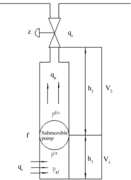
The schematic diagram of the submersible pump is shown in Figure 2:
Figure 2. Schematic diagram of submersible pump.
The symbols used in the latter mathematical deriva-tion are interpreted as follows:
`
p
q , qc and qr respectively represent the flow passing through the submersible pump, the flow pass-ing through the choke valve and the flow passpass-ing from the reservoir to the oil well. in
p and dis p respec-tively represent the pressure of the pump suction inlet and outlet. pwh, pwf and pr respectively represent
the pressure of the wellhead and downhole.
f
is the revolving frequency of the pump, and z is the choke valve. The finite volume of the well is divided into V1and V2, and their vertical height is respectively h1
and h2, the corresponding average velocity is
respec-tively q1 and q2, the corresponding density is
re-spectively 1 and 2, and the corresponding bulk
modulus is respectively and 1 and 2.
However, in the actual production, the value of in
p
directly affects the flow sucked from the oil reservoir, which means that the output of the raw petroleum will be less. Therefore, in fact, to control over the target is to control over the liquid inlet pressure of the sub-mersible pump approaching the set point sp
in p p , .
in
p → sp
in p
p , (1)
4 RESTRICTED CONDITIONS OF CONTROL
SYSTEM
In the actual production process, there is a need to satisfy the restraint of some conditions in order to ensure the safe operation and long-term use of the system.
The rotational frequency of the submersible motor is given by the motor manufacturer.
min
f
≤f
≤ maxf
(2)Restriction of the change rate of the submersible motor frequency:
f
≤ max
f
(3)Restriction of the opening and closing rate of the choke valve:
z
≤ max
z
(4)Restriction of the flow of the submersible pump:
0 0
f f qdt ≤
q
p≤0 0
f f
qut (5)
Where, dt q0 and
ut
q0 are respectively the maxi-mum and minimaxi-mum flow of the submersible pump fluid at a rated frequency of 50Hz.
Restriction of the lift of the submersible pump (H):
g
p
p
H
(
p,dis
p,in)
/
P (6)) ( ) ( )
( ) (
0 0 2
0 0
f f H f H H f H f f
Hut ut dt dt
(7)
Where, ut H0 and
dt
[image:3.516.88.219.307.487.2]5 MATHEMATICAL MODEL OF SUBMERSIBLE PUMP
5.1 Dynamic system model analysis
First, we carry out mechanical analysis of the pressure and flow of the pipeline in the well. The pressure
x tp , and the corresponding flow passing through its cross section (Q
x,t ) at a certain time in the pipe-line can be described by the following equation:x q t p A
(8)
Where, A is the cross sectional area of the position x, and the cross section is perpendicular to the heavy vertical line; and
respectively represent the bulk modulus and the fluid density; h is the vertical distance to the earth surface (if it is an inclined well, h is not equal to the length of the well), F is the pressure loss caused by the friction.We can use the finite volume method to disperse the above partial differential equation into an ordinary differential equation. For the oil production system of the submersible pump, the system is a great inertial system, and the dynamic change is very slow, so a large number of finite volumes are not necessary. As shown in Figure 2, we divide the models into V1 and
2
V . In order to simplify the equation, we propose the following hypothesis: Within the finite volume, the change rate of any pressure is the same with the change rate of the average pressure [10, 11].
x t p p
, (9)
After integration into the above equation, we ob-tain: out in q q P V
(10)
Where, in
q and out
q are respectively the flow of inflow and outflow control volume. Equation (4) is applied to
V
1 andV
2, then:p r
bh q q
P V 1 1
(11)
c p
wh q q
P
V
2 2
(12)Then, we assume that the fluid in the well is unable to be compressed in the steady-state system, and we can obtain the following differential equation of the flow:
f hs p wh
wf p p p p
p q
M
(13)
Where, M is the inertial parameter of the fluid, which is defined as follows:
A L L M1 12 2
(14)
hs
p
is the gravity and pressure difference of water between wellhead and downhole, which is defined as follows:
2 2 1
1
g
h
g
h
p
hs
(15)f
p
is an overall pressure loss caused by the fric-tion in the well, which is defined as follows according to Darcy-Weisbach formula [12]:
h D f D v L f P 2 2
(16)
Where, Dh is the hydraulic diameter of the
pipe-line, v is the flow velocity of the fluid, fD is Darcy friction coefficient, LL1L2.
5.2 Algebraic equation of system
The mathematical modeling is given to the lift of the submersible pump. The lift of pump is determined by the frequency of pump (f) and the fluid flow [13].
2 0 0 0 ) , ( f f f f q H q f
H p p (17)
Where, H0(q)is the equation of the lift of the submersible pump at a flow rate ofqand frequency of
0
f . In the simplest case,
(
)
0
q
H
is a monotone de-creasing second-order polynomial ofq
.2 2 0 1 2 2 0 0 ) ,
( p fqp aqp
f a f f a q f
H (18)
Where,
a
0,a
1 anda
2 respectively represent theconstant of the motor measured at a frequency of 50Hz, which are provided by the pump manufacturer.
The pressure difference of the pump (Pp) is equal
to: g q f H q f
pp p p p p
( , , ) ( , ) (19)
Bernoulli equation of the choke valve is:
man wh v c p p z C NWhere,
5
66 N /3600 10
N , N627.3; the
pa-rameter Cv
z is provided by the manufacturer of thechoke valve. Based on a commonly-used choke valve in the oil field, after fitting:
50 50 5
5
20 5 . 0
556 . 0 111 . 0 0
z z z
z z z
Cv (21)
Through analysis of the fluid flowing from the oil reservoir, we can obtain a common equation:
) ( r bh
r PI p p
q (22)
Where, PI is an index of the stored energy, which is a relatively constant index.
According to the above equations (11) (12) (13) (19) (20) and (22), we can obtain a simple and accurate dynamic model of the lifted well of the submersible pump.
6 PREDICTION CONTROL AND SIMULATION
RESULT OF SUBMERSIBLE PUMP
The set point of the pressure (pspp,in) can be obtained under a certain temperature based on the content in the second part. The change of the frequency of the motor and the opening degree of the choke valve can make the pressure of the actually measured pump suction inlet ( in
p ) close to pspp,in. The oil well is a high-inertia,
and strong-coupling system, so we will adopt double PI control. The first PI control is to control over the frequency of the submersible motor in order to change the flow velocity of extracted fluid in the well, thus changing the pressure of the pump suction inlet ( in
p ) and making it approach the set point pspp,in; the second
[image:5.516.266.460.461.535.2]PI control is to control over the opening degree of the choke valve. The choke valve will act with the chang-es of the prchang-essure difference between the upper and lower ends of the choke valve.
Figure 3. Variation curve of pump inlet pressure under single PI control.
Under normal circumstances, the choke valve will operate in a full open form. However, the choke valve
does not operate in a full open form, thus adding un-necessary energy consumption and reducing the out-put of raw petroleum. As shown in Figure 3, the curve is the pump inlet pressure varying from the set point under single PI control.
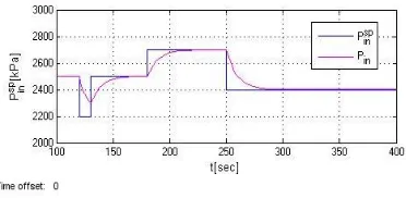
When the downhole system occurs, and the pressure difference between the upper and lower part of the choke valve changes, the choke valve operates; when the revolving speed of the pump tends to be smooth and steady, the choke valve will operate in a full open form. Figures 4-7 are variation curves of various pa-rameters of the oil well under double PI control. The choke valve operates at 120s and 250s. We observe that the pressure of the pump suction inlet closely follows with the preset value and becomes more ac-curate. We also observe that the revolving speed of the motor basically reaches a reasonable value. We can see that the double PI control can be more accurate and rapid to make the pressure closely follow with the set point, thus achieving the purpose of accurate pre-diction model in the case of the same condition of the entire oil production system of the submersible pump.
[image:5.516.60.246.516.607.2]The function of the choke valve is to make the pressure of the pump suction inlet closely follow with the pressure of the set point, so the response speed can be faster. More importantly, the inertia of the entire oil production system is relatively large. And in the case of non-adjustment, the revolving speed of the sub-mersible motor will be adjusted as the large inertia and hysteretic nature of the entire system, which could not accurately achieve the desired set value; with the ad-justment by the choke valve, it will set the speed of the submersible motor to be adjusted in advance; when the choke valve is fully open again, the revolv-ing speed of the submersible motor reaches the desired setting again. In summary, the double PI control can effectively prevent the flash steam phenomenon, and also improve the effectiveness of the entire system.
Figure 4. Variation curve of well pump pressure under double PI control.
) (f
[image:6.516.55.252.81.164.2]Hut so that the system can operate normally.
[image:6.516.58.251.200.270.2]Figure 5. Variation curve of opening degree of choke valve.
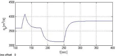
Figure 6. Variation curve of operating frequency of submersible pump.
Figure 7. Variation curve of submersible pump flow.
7 CONCLUSION
In the process of oil production by the use of SAGD technology, the downhole pressure, temperature and other parameters have a great impact on the safe oper-ation of the submersible pump. The operoper-ational ra-tionality of the submersible pump shall be improved as much as possible while improving the efficiency of oil production. Combined with the phase transition theory of the substance under a high pressure and high temperature, this paper based on the changes of the downhole pressure and temperature carries out non- linear analysis and modeling of the oil production system of the submersible pump, and adopts the method in combination with frequency converting control and a variety of control means in order to suc-cessfully avoid the changes of the downhole pressure, temperature and other parameters, produce serious liquid vaporization phenomenon and find an optimal working condition of the system.
According to the simulation experiment, under steady-state conditions, the revolving frequency of the motor under single PI control is sufficient, and the system is simple and stable. In order to preferably predict control under dynamic conditions, double PI control is used to make the control model accurately adjust the pump inlet pressure and follow with the set point of the pressure. The experimental result shows that the system is optimized so that the system can have a more stable and long-term operation, and less energy is consumed in the case of efficient oil produc-tion.
REFERENCES
[1] Mei Sijie & Shao Yongshi. 2000. Petroleum Engineer-ing. Beijing: Petroleum Industry Press, pp: 1-14. [2] Zheng Junde & Zhang Zhonghong. 2007. New progress
of oil production technique of foreign electric pump. Drilling & Production Technology, 30(1): 68-71. [3] Meng L Y, Wang W C. & Li Y X. 2010. Investigation
on online multiphase flow meter in oilfield based on open channel flow. 6th International Symposium on Multiphase Flow, Heat Mass Transfer and Energy Con-version, Xi’an, pp: 659-664.
[4] Semenov A A, Krasnov V A. & Khabibullin R A. 2010. New method for fluid level depression test interpretation based on modern multiphase flow calculation tech-niques. SPEEUROPEC 2010, Barcelona, pp: 1370-1380. [5] Yang Rui, Guan Zhigang & Jiang Gang, et al. 2009. Drilling technology of SAGD parallel horizontal well in oilfield of Wind City of Xinjiang. China Petroleum Ma-chinery, 37(8): 79-82.
[6] Alexey Pavlov, Dinesh Krishnamoorthy, Kjetil Fjalestad, Elvira Aske & Morten Fredriksen. 2014. Mul-ti-conference on Systems and Control. Modelling and Model Predictive Control of Oil Wells with Submersible pumps, pp: 586-592.
[7] Reedy M A. & Ershaghi I. 2008. Reducing electric pumping consumption in mature fields: Case studies. SPE Western Regional AAPG Pacific Section/GSA Cordilleran Section Joint Meeting, Anchorage, United States, pp.343-349.
[8] Wan Renpu & Luo Junying. 1996. Manual of Oil Pro-duction Technique. Beijing: Petroleum Industry Press, pp: 136-153.
[9] Liu Guiman, Ma Chunbao, Zhang Shimin, Gui Lieting, &Wang Chunsheng. 2010. Forecast of heavy oil produc-tion well bottom flash by steam flooding in Jin 45 block. Journal of Daqing Petroleum Institute, 6: 80-82. [10] Chen Zuobin. 2003. Computational Fluid Dynamics and
its Applications. National Defense Industry Press. [11] Li Renxian. 2008. Basis of Finite Volume Method.
Na-tional Defense Industry Press.
[12] K. E. Brown & H. D. Beggs. 1977. The technology of artificial lift methods, Volume I. Inflow Performance, Multiphase flow in pipes, The flowing well. Tulsa. Ok-lahoma. PennWell Publishing Company.
[image:6.516.57.253.312.407.2]