Systems
GA23-0060-0
File No. 5360/5370/53/4300-09
IBM 3270
Information Dis'play System
3271
Control Unit
3272
Control Unit
3275
Display Station
Description and
Programmer1s Guide
---
---
-
----
-
----
-
----
-
-
First Edition (November 1980)
The material in this publication was formerly contained in the IBM 3270
Information Display System Component Descn·ption, GA27-2749-10. For the
applicable publications for other units of the IBM 3270 Information Display System, see the IBM 3270 Information Display System Library User's Guide, GA23-0058.
It is possible that this material may contain reference to, or information about, IBM products (machines and programs), programming, or services that are not announced in your country. Such references or information must not be construed to mean that IBM intends to announce such IBM products, programming, or services in your country.
Publications are not stocked at the address given below; requests for IBM publications should be made to your IBM representative or to the IBM branch office serving your locality.
A form for readers' comments is provided at the back of this publication. If the form has been retnoved, address comments to IBM Corporation, Department 52Q, Neighborhood Road, Kingston, N.Y. 12401. IBM may use or distribute any of the information you supply in any way it believes appropriate without incurring any obligation whatever. You may, of course, continue to use the information you supply.
Preface
This publication provides management, programmers, and system analysts with detailed reference material relating to the IBM'3270 Information Display System. The 3270 display system comprises the following units:
• IBM 3271 Control Unit Models 1,2, 11, and 12
• IBM 3272 Control Unit Models 1 and 2
• IBM 3275 Display Station Models 1, 2, 11, and 12
• IBM 3277 Display Station Models 1 and 2
• IB~ 3284 Printer Models 1, 2, and 3 • IBM 3286 Printer Models 1 and 2
• IBM 3287 Printer Models 1 and 2
• IBM 3288 Line Printer Model 2
Organization of This Publication
This publication is divided into eight chapters:
Chapter 1, Introduction, contains a general description of the individual 3270 units and features, and presents local and remote attachment configurations and system concepts.
Chapter 2, Terminal Operations, contains information on data buffering and display image and printout formatting. Display, keyboard, selector pen, printer, and operator identification card reader operations are described in de-tail.
Chapter 3, Commands and Orders, describes in detail the functions of the commands and orders that can be executed by the 3270.
Chapter 4, Local Operations, outlines the unique operations of locally attached 3270 systems. Described are operations with the channel, selection, command initiation and chain-ing, status bit definition, and error-recovery procedures.
Chapter 5, Remote Operations-BSC, discusses the unique operations of remotely attached 3270 systems using binary synchronous communication (BSC) line discipline. De-scribed are BSC procedures, the functions and usage of data link control characters, 3270 command, selection, and polling operational sequences (including interaction with the access. method and the channel program), remote 3270 command chaining, and error-recovery procedures.
Chapter 6~ Remote Operations-SDLC, discusses the
opera-tion of remotely attached 3270 systems using synchronous data link control (SDLC) line discipline. This section
describes command operation, data transfer, and error-recovery procedures.
Chapter 7, Screen Design, discusses the elements of screen design, field concepts, panel design, data stream coding, and the relationship between data streams.
Chapter 8, Screen Management, discusses the decoding and generating of data streams.
This publication also has six appendixes:
Appendix A, Indicators and Controls
Appendix B, Buffer Address I/O Interface Codes
Appendix C, Katakana Feature
Appendix D, Data Analysis-APL Feature
Appendix E, Abbreviations
Appendix F, Glossary
Related Publications
This document assumes that the reader has read the following publications, as appropriate:
• IBM System/360 Principles of Operation, GA22-6821 • IBM System/370 Principles of Operation, GA22-7000 • General Information-Binary Synchronous
Communi-cations, GA27-3004
• IBM Synchronous Data Link Control General Informa-tion, GA27-3093
• IBM 2701 Data Adapter Unit Component Description,
GA22-6824
• IBM 2703 Transmission Control Component Descrip-tion, GA27-2703
• Introduction to the IBM 3704 and 3705 Communi-cations Controllers, GA27-305l
• IBM System/3 Model 10 Components Refer{!nce Manual,
GA21-9103
• IBM System/3 Model 10 Multi-line/Multi-point Binary Synchronous Communications Reference Manual,
GC21-7573
• IBM Systems Network Architecture General Information, GA27-3l02
• Virtual Storage Supplement, GC20-000 1 , for IBM System/360 and System/370 Bibliography,
The following publications may also be of interest:
• An Introduction to the IBA13270 Information Display System, GA27-2739
• Operator's Guide for IBM 3270 Information Display Systems, GA27-2742
• IBM 3270 Information Display System Conjigurator,
GA27-2849
• IBM 3270 Information Display System: Character Set Reference, GA27-2837
For a description of all 3270 publications, see the IBM 3270 Information Display System: Library User's Guide,
GA23-0058
Contents
Chapter 1. Introduction 1-1 Display System Components 1-1
Control Unit 1-1 Display Station 1-2 Printer 1-2
Display System Configurations 1-3 Local Attachment 1-3 Remote Attachment 1-3
Remotely Attached 3270 Systems Using BSC Operating Mode 1-6
Remotely Attached 3270 Systems Using SDLC Operating Mode 1-6
Teleprocessing Networks and Modems 1-7 Features 1-7
System Concepts 1-7 Data Stream 1-8 Interface Codes 1-8
Local and Remote Operations 1-8
Chapter 2_ Terminal Operations 2-1 Buffer Concepts 2-1
Display Operations 2-2 Display Images 2-2
Unformatted and Formatted Display Images 2-3 Display Fields 2-7
Keyboard Operations 2-9 Cursor 2-10
Keyboards 2-10 Key Functions 2-12
Numeric Lock Special Feature Operation 2-15
Keyboard Disabled (INPUT INHIBITED Indicator On) 2-15 Indicators and Controls 2-16
Selector-Pen Operations 2-16 Selector-Pen Field Format 2-17 Designator Characters 2-17 Security Keylock 2-19
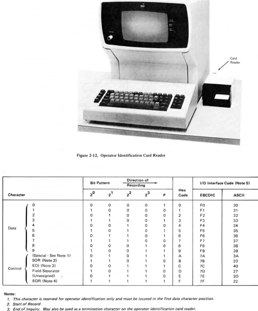
Operator Identification Car,d Reader 2-19 10-Character Set 2-21
Magnetic-Stripe Format 2-21
Operational Differences Due to Screen Format 2-21 Error Conditions 2-25
Printer Operations 2-26 Print Line Formatting 2-26 NL, EM, and FF Printer Orders 2-26 Buffered Printer Operations 2-28 Unbuffered Printer Operations 2-28 Page Length Control/VFC Operations 2-29 Error Conditions 2-30
Not Ready 2-30
Character Generator or Sync Check Errors 2-31 Parity Error 2-31
Command-Chaining 2-31
Unit and Model-Dependent Differences 2-31 Buffer Size 2-31
Uppercase and Lowercase Printouts 2-31 Split Vertical Bar ( D Character 2-31 Chapter 3. Commands and Orders 3-1 Commands 3-1
Timing Considerations 3-1 Read Commands 3-2
Read Buffer Command 3-3
Read Modified Command 3-4 Write Commands 3-7
Write Command 3-8 Erase/Write Command 3-10 Control Commands 3-10
Copy Command 3-10 Select Command 3-12
Erase All Unprotected Command 3-12 No Operation Command 3-13 Sense Command 3-13
Orders 3-14
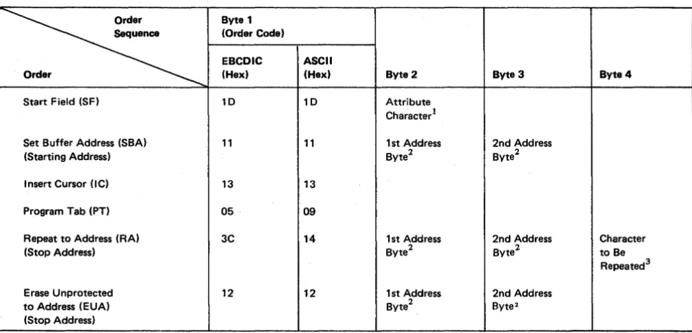
Start Field (SF) Order 3-14
Set Buffer Address (SBA) Order 3-15 Insert Cursor (IC) Order 3-15 Program Tab (PT) Order 3-15 Repeat to Address (RA) Order 3-16
Erase Unprotected to Address (EUA) Order 3-16
Chapter 4. Local Operations (3272 Models 1 and 2) 4-1 Introduction 4-1
Interface Operations 4-1 Selection 4-1
Command Initiation 4-4 Chaining 4-4
Status 4-4
Initial Status 4-6 Ending Status 4-7 Asynchronous Status 4-7 Error-Recovery Procedures 4-11
3272 Device-Detected Errors 4-11 Recommended Procedures 4-11 Channel-Detected Errors 4-12
Chapter 5. Remote Operations - BSC (3271 and 3275 Models 1 and 2) 5-1
Introduction 5-1 Code Structures 5-1
Channel Program Concepts ~-1
Text Blocking 5-11 Related Publications 5-2
Multipoint (Nonswitched Line) Data Link Control 5-2 3270 Modes of Operation 5-2
Control Mode 5-3 Text Mode 5-3
Transparent Monitor Mode 5-3 Redundancy Checking 5-3 Data-Link Control Characters 5-4
Pad 5-5
SYN (Synchronous Idle) 5-5 DLE (Data Link Escape) 5-5 ACK 0 (Even Acknowledge) 5-5 ACK 1 (Odd Acknowledge) 5-5 NAK (Negative Acknowledgment) 5-5 ENQ (Enquiry) 5-6
WACK (Wait before Transmit) 5-6 R VI (Reverse Interrupt) 5-6 STX (Start of Text) 5-6 SOH (Start of Heading) 5-6
ETB (End of Transmission Block) 5-7 ETX (End of Text) 5-7
ITB (End of Intermediate Transmission Block) 5-7 ESC (Escape) 5-7
TTD (Temporary Text Delay) 5-7 Operational Sequences (Nonswitched Line) 5-7
Remote Chaining of 3270 Commands 5-8 General and Specific Poll Sequences 5-8 Selection Addressing Sequence 5-13
Write-Type and Control-Type Command Sequences 5-16 Read-Type Command Sequences 5-16
Status and Sense (S/S) Bytes 5-17 Error-Recovery Procedures 5-17
Supplementary Procedures 5-27 NAK to a Text Block 5-28 EOT to a Text Block 5-28
Errors Detected during a Specific or General Poll Sequence 5-28
RVI to Selection Addressing Sequence 5-28 Point-to-Point (Switched Line) Data Link Control 5-28
Terminal Identification 5-28 Contention Line Discipline 5-29
Bid Sequence 5-29 3275-Initiated Call 5-29 Computer-Initiated Call 5-29 Disconnection 5-30
Data Link Control Characters 5-30
ACK 0 and ACK 1 (Positive Acknowledgment) 5-30 NAK (Negative Acknowledgment) 5-30
ENQ (Enquiry) 5-30 R VI (Reverse Interrupt) 5-31 EOT (End of Transmission) 5-31 DLE EOT (Disconnect) 5-31 Operational Sequences (Switched Line) 5-31
3275-Initiated Sequences 5-31 TCU-Initiated Sequences 5-31 Maintained Connection Sequences 5-35 Device Busy and Device End 5-35
Chapter 6. Remote Operations - SDLC (3271 and 3275 Models 11 and 12) 6-1
Introduction 6-1 Related Publications 6-1
Multipoint (Nonswitched Line) Data Link Control 6-1 SDLC Transmission Blocks 6-2
Link Test Command/Response 6-3 Information (I) Field 6-3
Transmission Header (TH) 6-4 Request/Response Header (RH) 6-5 Command Byte 6-8
3270 CU Responses 6-8
Data Transmissions by the 3270 CU 6-10 Control Functions 6-11
SDLC Sequence/Response Diagrams 6-12 Status and Sense (S/S) Bytes 6-12 Error-Recovery Procedures 6-21
Timeout to a Poll 6-23
CMDR Response to Invalid Nonsequenced Commands and I-Field Formats 6-23
ROL Response to a Poll 6-23 Aborting an Inbound I-Frame 6-23
Chapter 7. Screen Design 7-1 Field Concept 7-1
vi
How Fields Are Defined 7-1
What Attributes May Be Assigned to a Field 7-2 Protection 7-2
Character Content 7-2
Visibility and Detectability 7-2 Transmission 7-3
Example of Field DefInition 7-4 Field 1: SIGN-0NPROCEDURE 7-4
Field 2: PLEASE ENTER ... INFORMATION 7-4 Field 3: NAME: 7-5
Field 4: The Area Following "NAME:" 7-5 Field 5: LOCATION: 7-5
Field 6: The Area Following "LOCATION:" 7-5 Field 7: SERIAL NUMBER: 7-5
Field 8: The Area Following "SERIAL NUMBER:" 7-6 Field 9: The Area between the Additional Attribute
Described in Field 8 and "WHEN ALL ... KEY" 7-6 Field 10: WHEN ALL ... KEY 7-6
Panel Design 7-7
An Example of a Sequence of 3270 Panels 7-7 Planning a Sequence of Panels 7-11
DefIning the Purpose of Each Panel 7-12 Using the Panel Layout Sheet 7-12 An Example of Laying Out a Panel 7-13 Data Stream Coding 7-15
Orders 7-15
Adding Orders to the Panel Layout Sheet 7-15 Coding the Panel 7-19
Repeat to Address Order 7-22 Write Control Character (WCC) 7-23 Analyzing Input Data 7-24
The Operator's Response 7-24 Attention Identifier (AID) 7-25 Input Data 7-25
SBA Codes 7-27 Program Access Keys 7-27
Program Attention (PA) Keys 7-27 Program Function (PF) Keys 7-28 Selector-Pen Input and Output 7-28
Selector-Pen Field Format 7-28 Designator Characters 7-29
The Relationship of One Data Stream to Another 7-30 Modifying Existing Panels 7-30
Write Control Character (WCC) 7-32 Erase Unprotected to Address 7-33 Erase All Unprotected Command 7-35 Repetitive Output 7-37
Program Tab 7-37
Chapter 8. Screen Management 8-1 Decoding and Generating Data Streams 8-1
Decoding Read ModifIed Input Data Stream 8-2 Non-Selector-Pen Data Streams 8-3
Immediate Selector-Pen Data Stream 8-6 Mixed Read ModifIed Input Data Streams 8-7 Building Output Data Streams 8-7
Static Data Streams 8-8
Semidynamic Output Streams 8-11 Dynamic Output Streams 8-11
Copy Function for the 3271 and 3272 8-12
Appendix A. Indicators and Controls A-I
Appendix B. Buffer Address I/O Interface Codes B-1
Appendix C. Katakana Feature C-I Interface Codes C-I
Appendix D. Data Analysis - APL Feature D-1 APL Keyboard Special Feature Operation (3277 Display
Station Model 2) D-4 APL ON/OFF Key D-4 APL ALT Key D-4
Text Keyboard Special Feature Operation (3277 Display Station Model 2) D-6
ALT ON/OFF Key D-7 CODE Key D-7
ERASE EOF /TEST REQ Key D-7
Figures
Frontispiece. IBM 3270 Information Display System: 3271/ 3272 Control Unit, and Attached 3277 Display Station and 3284/3286 Printer x
1-1. Locally Attached 3270 Information Display System 1-4 1-2. Remotely Attached 3270 Information Display System 1-5 2-1. Data Flow between Data Processing System and 3270
Information Display System 2-1
2-2. Relationship between Display Station Buffer and Charac-ter Position Display Image (Unformatted Display) 2-3 2-3. Buffer Addressing Layouts for Modell and
Model 2 Devices 2-4
2-4. Examples of Display Image Fields (Formatted Display) 2-4 2-5. United States I/O Interface Code-EBCDIC 2-5
2-6. United States I/O Interface Code-ASCII 2-6 2-7. Control Character I/O Codes 2-8
2-8. Attribute-Character Bit Definition 2-9
2-9. Basic Keyboards for 3277 and 3275 Display Stations 2-11 2-10. Selector Pen 2-16
2-11. Sample Display Screen for Selector-Pen Operations 2-18 2-12. Operator Identification Card Reader 2-20
2-13. 10-Character Set Used with Operator Identification Card Reader 2-20
2-14. Magnetic-Stripe Format (10-Character Set) 2-21 2-15. Operation of the Display with an Unformatted Screen
(Using 10-Character Set) 2-22
2-16. Operation of the Display with a Formatted Screen (Using 10-Character Set), Example 1 2-23
2-17. Operation of the Display with a Formatted Screen (Using 10-Character Set), Example 2 2-24
2-18. Relationship between Buffer Data and Printed Data 2-27 3-1. Local and Remote Command Codes 3-1
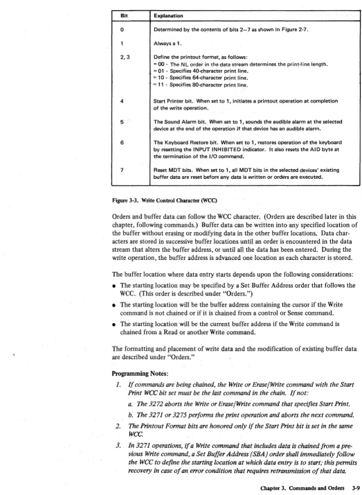
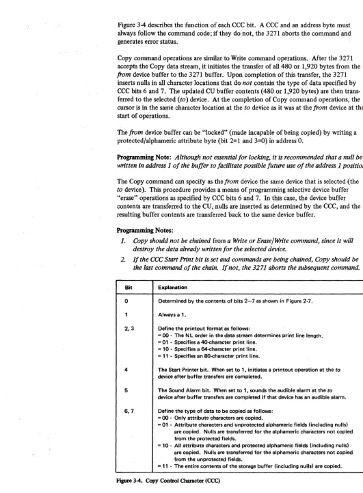
3-2. Attention ID (AID) Configurations 3-4 3-3. Write Control Character (WCC) 3-9 3-4. Copy Control Character (CCC) 3-11 3-5. Sense Bit Description 3-13
3-6. Buffer Control Orders and Order Codes 3-14
4-1. Locally Attached 3270 Information Display System 4-2 4-2. 3272 and Device Addressing - 16 or Fewer Devices
per Control Unit 4-3
4-3. 3272 and Device Addressing - 17 or More Devices per Control Unit 4-3
New Line Key D-8
Tab and Backtab Functions D-8 3288 Printer/Text Feature D-9
Appendix E. Abbreviations E-1
Appendix F. Glossary F-1
Index X-I
4-4. Status-Byte Bit Assignments for 3272 4-5 4-5. Initial Status and Sense Conditions for 3272 4-6 4-6. Ending Status and Sense Conditions for 3272 4-8 4-7. Asynchronous Status and Sense Conditions for
3272 (2 parts) 4-9
5-1. General Poll and Specific Poll, Sequence/Response Diagram (2 parts) 5-10
5-2. Remote Control Unit and Device Addressing-BSC 5-12 5-3. 3270 CU Message Response to Polling or Read Modified
Command 5-13
5-4. Selection Addressing, Sequence/Response Diagram (2 parts) 5-14
5-5. Write-Type and Control-Type Commands, Sequence/ Response Diagram-BSC (2 parts) 5-18
5-6. Read-Type Command, Sequence/Response Diagram-BSC (2 parts) 5-20
5-7. Remote Status and Sense Byte Delmitions-BSC 5-22 5-8. Remote Error Status and Sense Responsed-BSC
(3 parts) 5-23
5-9. Remote Status and Sense Conditions-BSC 5-26 5-10. 327 5-lnitiated Transmission, Sequence/Response
Diagram 5-32
5-11. Status Message Transmission with Dial Feature, Sequence/Response Diagram 5-33
5-12. TCO-Initiated Transmission, Sequence/Response Diagram 5-34
5-13. Example of Maintained Connection, Sequence/Response Diagram (2 parts) 5-36
6-1. Remote Control Unit and Device Addressing-SDLC 6-6 6-2. Request and Response Format 6-9
6-3. Online and Offline Procedures, Sequence/Response Diagram 6-13
6-4. Read-Type Command, Sequence/Response Diagram-SDLC (2 parts) 6-14
6-5. Write-Type Command, Sequence/Response Diagram-SDLC (2 parts) 6-16
6-6. Remote Status and Sense Byte Definitions-SDLC 6-18
6-7. Remote Error Status and Sense Responses and Requests-SDLC (2 parts) 6-19
7-1. Example of Four Fields and Attribute Bytes 7-1 7-2. Results of Keyboard and Field Combinations 7-3 7-3. Example of Attribute Specification 7-4 7-4. An Example of a Panel 7-7
7-5. Another Example of a Panel 7-7
7-6. Panel 1 of an Accounts Receivable Application 7-8 7-7. Panel 2, Showing the Results of a Search on a
Customer Name 7-9
7-8. Panel 3, Showing the Customet~s Open Invoices 7-9 7-9. Pane14, Showing Use of the Calculator 7-10 7-10. PanelS, Showing Selection ofInvoices after Use of
the Calculator 7-10
7-11. Panel 6, Showing New Balance after Posting 7-11 7-12. Sign-On Panel Block Diagram 7-12
7-13. Block Diagramming 7 -12
7-14. Sign-On Panel as Written Out on Layout Sheet 7-13 7-15. Panel Layout, Including Attribute and Cursor
Positions 7-14
7-16. Laying Out Field Attributes 7-14 7-17. Text Items on Panel Layout Sheet 7-16 7-18. Field Attributes 7-16
7-19. -Attribute Default Values 7-17
7-20. Completed Order and Attribute Information 7-17 7-21. Buffer Control Orders and Order Codes 7-19 7-22. Sign-On Procedure Panel Orders and Attributes 7-20 7-23. Attribute Character Combinations in Hexadecimal 7-21 7-24. Assembler Language Statements for Sign-On Panel 7-22 7-25. Example of RA Order 7-23
7-26. WCC Hexadecimal Codes 7-24
7-27. Sign-On Panel with Operator's Input 7-25 7-28. Input Data Sequence 7-25
7-29. Attention Identifiers (AIDs) in Hexadecimal Codes (EBCDIC) 7-26
7-30. Definition of Field for Selector-Pen Operation 7-28
viii
7-31. Sample Panel for Selector-Pen Detection 7-29 7-32. Modifying an Existing Panel-Basic Panel 7-31 7-33. Existing Panel with Error Message 7-31 7-34. Panel Layout Changes for Error Message (Keyed
to Text) 7-34
7-35. Error Message Panel with Serial Number Field Erased 7-34 7-36. Example of EUA Use 7-34
7-37. Sign-On Panel with Three Erased Fields 7-35 7-38. Erasing Multiple Fields with EUA 7-35 7-39. Example of Data Entry Panel 7-36 740. Data Entry Panel with Entered Data 7-37 7-41. Employee Data Panel 7-37
7-42. Panel Defined with Program Tab 7-38
8-1. Relationship of Screen Management to Telecommunication Management and Application Programs 8-1
8-2. Table of Requirements 8-4 8-3. Example of Selector-Pen Panel 8-7 8-4. Sample of Mapping Table 8-7 A-I. Indicators and Controls A-I
A-2. Indicators and Controls for 3287 Printer (4 parts) A-5 C-l. Japanese Katakana EBCDIC I/O Interface Code C-l D-1. D-2. D-3. D-4. D-5. D-6. D-7. D-8.
Data Analysis-APL Feature and Associated Features Data Analysis-APL Interface Codes (2 parts) D-2 APL Keyboard D-4
APL Keyboard Feature Character Set D-5 APL Keyboard TN Character Availability D-6 Text Keyboard D-7
Text Keyboard Feature Character Set D-8 Text Print Character Set for 3288 Printer Model 2 D-9
D-9. 3288 Variant of EBCDIC for Text Print Feature D-I0
D-IO. 3288 Text Print Restricted Character Set (Copy Command) D-ll
Frontispiece. IBM 3270 Information Display System: 3271/3272 Control Unit, and Attached 3277 Display Station and 3284/3286 Printer
Chapter 1. Introduction
Display System Components
Control Unit
An example of an IBM 3270 Information Display System is shown in the frontispiece. The 3270 system offers the user a wide selection of components and configurations. Also available are a large variety of standard and special features that improve perform-ance, provide additional operational capability, and permit expansion of the display system. See the IBM 3270 Information Display System Configurator, GA27-2849, for features and configurations.
The 3270 system can attach locally (via cable) or remotely (via common carrier or equivalent facilities) to a host sytem. Remote systems employ binary synchronous communication (BSC) or synchronous data link control (SDLC) line discipline.
The 3270 Information Display System has three. types of components: control unit, display station, and printer.
The control unit provides for the 3270 system's attachment to a data processing system.
It directs the operation of up to 32 attached 3270 display stations an~ printers. Two control units of the 3270 system are described in this pUblication:
3271 Control Unit
• Models 1 and 11 have a 480-character buffer capacity.
• Models 2 and 12 have a 1 ,920-character buffer capacity.
• Models 1 and 2 attach to a System/360 or System/370 via modems and a BSC data link, and operate with any of the following: an IBM 2701 Data Adapter Unit, an IBM 2703 Transmission Control Unit (TeU), an integrated communication adapter, or an IBM 3705 Communications Controller.
• Models 1 and 2 attach to System/3 Model 10 via a System/3 BSC adapter or to System/3 Model 15 via the local communication adapter.
• Models 11 and 12 attach to a System/370 via modems and an SDLC communication link, and operate in Network Control Program (NCP) mode with an IBM 3704 or 3705 Communications Controller.
• Models 1 and 2 attach to the 4300 Processors via a 2701 Data Adapter Unit or a 3704 or 3705 Communications Controller, and to the 4331 Processor via the communication adapter.
3272 Control Unit
• Model 1 has a 480-character buffer capacity.
• Model 2 has a 1 ,920-character buffer capacity.
• The unit attaches to aSystem/360 or System/370 via a selector, multiplexer, or block multiplexer channel.
Display Station
Printer
1-2
The display station provides image display of data transmitted from the data processing unit. A display station with an attached keyboard enables the user to enter, modify, or delete data on the display, and to cause the revised display to be returned to the process-ing system for storage or additional processprocess-ing. Two display stations of the 3270 system are described in this publication:
3275 Display Station
• Models 1 and 11 have a 480-character buffer capacity.
• Models 2 and 12 have a 1,920-character buffer capacity.
• Models 1 and 2 are stand-alone units that attach to a System/360 or System/370 via
modems or data access a~rangements (DAAs) and any of the following: an IBM 2701,
an IBM 2703, an integrated communication adapter, or an IBM 3705 Communications Controller.
• Models 1 and 2 attach to System/3 Modell 0 or 15 via a BSC adapter or the local communication adapter.
• Models 11 and 12 attach to System/370 via modems and an SDLC communication link, and operate in NCP mode with a 3704 or 3705 Communications Controller.
3277 Display Station
• Modell has a 480-character display image.
• Model 2 has a 1 ,920-character display image.
• Modell attaches to a 3271 Control Unit (all models) or to a 3272 Control Unit Modell or 2.
• Model 2 attaches to a 3271 Control Unit Model 2 or 12 or to a 3272 Control Unit Model 2.
• Models 1 and 2 attach to the 3791 Controller (3790 Communication System).
The printer provides printed copy of data displayed at a display station or of data trans-mitted from the data processing system. Four printers of the 3270 system are described
in this publication:
3284 Printer
• Modell has a 480-character buffer capacity with a 40-cps print rate.
• Modell attaches to a 3271 or a 3272 Control Unit (all models).
• Model 2 has a 1 ,920-character buffer capacity with a 40-cps print rate.
• Model 2 attaches to a 3271 Model 2 or 12 or to a 3272 Control Unit Model 2.
• Model 3 has no buffer; the print rate is 40 cps.
• Model 3 attaches to a 3275 Display Station (all models).
3286 Printer
• Modell has a 480-character buffer capacity with a 66-cps print rate.
• Modell attaches to a 3271 or a 3272 Control Unit (all models).
• Model 2 has a 1 ,920-character buffer capacity with a 66-cps print rate.
3287 Printer
• Modell has a 480- or 1 ,920-character buffer capacity with an 80-cps maximum print rate and 132 print positions.
• Model 2 has a 480- or 1 ,920-character buffer capacity with a 120-cps maximum print rate and 132 print positions.
• Both models attach to a 3271 or 3272 Control Unit (all models).
3288 Line Printer (Model 2 only)
• Model 2 has a 1 ,920-character buffer capacity. The average print rate is 120 lines per minute.
• Model 2 attaches to a 3271 Control Unit Model 2 or 12 or a 3272 Control Unit Model 2.
Display System Configurations
Local Attachment
Remote Attachment
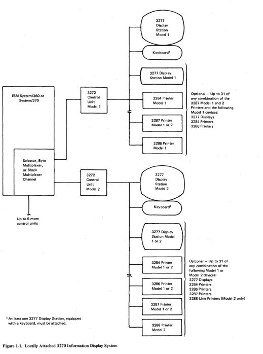
Locally attached 3270 display systems (Figure 1-1) use a 3272 Control Unit Modell or 2. The 3272 Control Unit Modell can communicate with up to 32 devices, con-Sisting of Model-l 3277 display stations, Model-l 3284 or 3286 printers, and Model-l or Model-2 3287 printers. The 3272 Control Unit Model 2 can attach up to 32 devices, consisting of Model-1 or Model-2 3277 display stations, Model-1 or Model-2 3284, 3286, or 3287 printers, and Model-2 3288 Line Printers. At least one display station with a keyboard must be attachedto any control unit. The 3272 is attached to a System/360 or System/370 through a block multiplexer, a byte multiplexer, or a selector channel via one of the eight control unit positions on the channel interface. The channel provides the 3272 with data to be displayed and with control information needed to direct the operation of the display station or printer attached to the 3272. Separate buffer storage in the display stations or printers holds digitally coded data for display or printing.
Remote attachment differs from local attachment in the medium through which the control unit and the system channel communicate. In a local configuration, the control unit is cabled directly to the system channel. In remote attachment, common-carrier (or equivalent customer) facilities of unlimited length are employed to communicate between the host and the 3270 system.
IBM System/360 or System/370
Selector, Byte Multiplexer, or Block Multiplexer Channel
Up to 6 more control units
1 At least one 3277 Display Station, equipped with a keyboard, must be attached.
3272 Control Unit Model 1
[image:14.617.39.559.41.739.2]3272 Control Unit Model 2
Figure 1-1. Locally Attached 3270 Infonnation Display System
1-4
Keyboardl
3277 Display Station Model 1
3284 Printer Model 1
3287 Printer Model 1 or 2
3286 Printer Model 1
3277 Display Station Model 1 or 2
3284 Printer Model 1 or 2
3286 Printer Model 1 or 2
3287 Printer Model 1 or 2
3288 Printer Model 2
Optional - Up to 31 of any combination of the 3287 Model 1 and 2 Printers and the following Model 1 devices: 3277 Displays 3284 Printers 3286 Printers
Optional - Up to 31 of any combination of the following Model 1 or Model 2 devices: 3277 Displays 3284 Printers 3286 Printers 3287 Printers
IBM System/360 (if using BSC line control) or System/ 370 (if using BSC or SDLC line control)
Multiplexer Channel
Transmission Control Unit
(TCU)l Line Adapter Feature To other control units Nonswitched Line
3271 Ctrl
Unit .... -"T""--I
Model 4
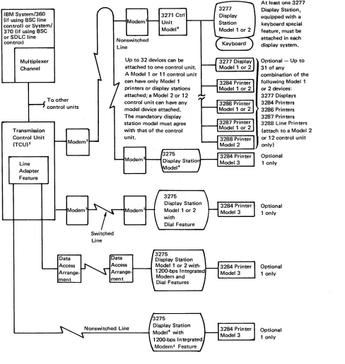
Up to 32 devices can be attached to one control unit. A Model 1 or 11 control unit can have only Model 1 printers or display stations attached; a Model 2 or 12 control unit can have any model device attached. The mandatory display station model must agree with that of the control unit.
3275
Modem
Display Station Model 1 or 2 with Data Access ment Switched Line Data ment
Dial Feature
3275
Display Station Model 1 or 2 with 1200-bps Integrated Modem and Dial Features
Nonswitched Line Display Station
_---~ Model4 with
1200-bps Integrated Modems Feature
At least one 3277 Display Station, equ ipped with a keyboard special feature, must be attached in each display system.
Optional - Up to 31 of any
combination of the following Model 1 or 2 devices: 3277 Displays 3284 Printers 3286 Printers 3287 Printers 3288 Line Printers (attach to a Model 2 or 12 control unit only) Optional 1 only Optional 1 only Optional 1 only Optional 1 only
12701 Data Adapter Unit, 2703 Transmission Control (non-switched with external modem only), 3705 Communications Controller, or equivalent Integrated Communication Adapter. In addition, the 3705 Communications Controller attaches to a selector or block multiplexer channel. In BSC mode, the choice of unit is dependent upon the processing system model, the type of channel, and the communication network selected. SDLC mode of operation requires a 3704 or 3705 Communications Controller.
21BM 3872,3874,3875, or 4872 Modems (or equivalent), as required. When switched network backup capability is provided, an IBM 3872, 3874, or 3875 modem is used, with a dial telephone attached, to communicate with the transmission control unit.
Figure 1-2. Remotely Attached 3270 Information Display System
3 1200-bps operation only.
[image:15.612.67.555.57.572.2]Remotely Attached 3270 Systems Using BSC Operating Mode
A 3271 Control Unit Modell or 2 or a 3275 Display Station Modell or 2 is used to remotely attach a 3270 system to the teleprocessing network employing BSC operating mode, allowing communication with a host System/360 or System/370. A 2701 Data Adapter Unit, a 2703 Transrriission Control Unit, a 3705 Communications Controller, or an equivalent integrated communication adapter, depending upon the host system and channel selected, connects the teleprocessing network to the host system channel.
The 3271 Control Unit Modell can attach up to 32 devices, consisting of Model-l 3277 display stations and Model-l 3284 or 3286 printers, or Model-lor Model-2 3287 printers.
The 3271 Control Unit Model 2 can attach up to 32 devices, consisting of Model-l or Model-2 3277 display stations, Model-lor Model-2 3284, 3286, or 3287 printers, and Model-2 3288 line printers. One display station with a keyboard must attach to each control unit. The model number of the display station and that of the control unit must be the same.
The 3275 Display Station Modell or 2 provides added convenience for remote locations that require a single display device. The 3275 functions as a control unit and as a display station, and is therefore more economical than a 3271 with a single 3277 attached. The 3275 capabilities can be expanded by attaching a 3284 Printer Model 3 to provide a paper copy of displayed messages. The 3275 can be attached to (multidropped from) the same nonswitched communication line as other 3270 display systems and other IBM products that use the BSC mode of operation, or, with the Dial feature installed, it can be attached by use of a point-to-point common-carrier switched network.
Remotely Attached 3270 Systems Using SDLC Operating Mode
1-6
When employing SDLC line discipline, the 3270 system is remotely attached to a host System/370 via a 3271 Control Unit Model 11 or 12, or a 3275 Display Station Model 11 or 12, over a teleprocessing network. A 3704 or 3705 Communications Controller is . required for this configuration. Display data and control information are relayed from the host system channel by the communications controller to the 3271 or 3275 Model 11 or 12 unit, via modems and common-carrier voice-grade lines.
The 3271 Control Unit Model 11 can communicate with up to 32 devices, consisting of Model-l 3277 Display Stations, 3284 or 3286 Modell Printers, and 3287 Modell or 2 Printers.
The 3271 Control Unit Model 12 can direct the operation of up to 32 Model-lor Model-2 3277 Display Stations, 3284, 3286, or 3287 Printers, or Model-2 3288 Printers.
At least one display station with a keyboard must attach to a control unit.
Teleprocessing Networks and Modems
Features
System Concepts
Remotely attached 3270 display systems that use BSC or SDLC line discipline operate in ' half-duplex transmission mode on half-duplex or full-duplex communication facilities.
The 3271 Modell or 2 can attach to a multipoint nonswitched line network. The 3275 Model 1 or 2 can operate in multipoint mode on nonswitched lines or on switched network lines when the Dial feature is installed.
The 3271 and 3275 Models 11 and 12 can attach to multipoint nonswitched line net-works. Messages may be simultaneously transmitted and received by the 3704 or 3705 units on full-duplex facilities (duplex-multipoint operation), when two or more SDLC devices are multidropped and attached to the same communications controllers.
IBM modems that can be used in remote systems that employ BSC or SDLC line control (specified in Figure 1-2) are as follows: '
• 3872 Modell (2,400 bps)
• 3874 Modell (4,800 bps)
• 4872 Models 1 and 3 (4,800 bps)
• 3875 Modell (7,200 bps)
Switched network backup is a method of replacing a failing nonswitched line with a switched communication system. This capability is available when the IBM 3872 and 3875 Modems are being used. The 3875 operates on nonswitched lines at transmission spee'ds of 7,200 and 3,600 bps, and on switched lines at speeds of 3,600 and 1,800 bps. The 3872 operates at transmission speeds of 2,400 and 1,200 bps on both nonswitched
and switched lines. If an excessively high error rate occurs during operation on a non-switched line at the maximum transmission speed (7,200 or 2,400 bps), the speed is reduced by one-half at both modems used in the system, and a check is made for a continued high error rate. If the error rate is still high, the display-terminal operator establishes a switched-line connection by dialing the 2701 (or equivalent unit). If the 3872 or 3875 modem was operating at half-speed when the error condition began, the operator establishes the switched-line connection without first changing the transmission speed. The lower line speeds available for dial operation (1,800 or 1,200 bps) may be used if too many errors occur at the higher line speeds.
No attempt has been made in this publication to catalog all the features available for the 3270 system, although some features are discussed. For details on the availability of various 3270 features, see the IBM 3270 Information Display System Configurator, GA27-2849, or discuss the matter with your IBM sales representative.
The 3271 and 3272 Control Units and the 3275 Display Station control the operations of, and the transfer of data to or from, their attached terminals. See Chapter 2, Terminal Operations, for details.
Data Stream
Interface Codes
Local and Remote Operations
1-8
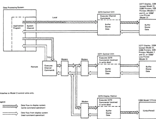
The 3270 data stream consists of user-provided data, commands, and orders transmitted between the control unit and the host system (Figure 2-1). Control information, which governs the movement of the data stream, is also transmitted. The control units carl differ as to the type of commands and/or transmission protocols employed.
Commands are issued to initiate such operations as the total or partial writing, reading, and erasing of data in a selected 3270 device buffer. Orders can be included in write data streams, either alone or intermixed with display or print data.
Two types of orders are available. One type is executed as it is received by the control unit. This type is used to position, define, and format data being written into the buffer, to erase selected unprotected data in the buffer, and to reposition the cursor. The second type or order specifies printer format. These orders are initially stored in the buffer as data and are executed only during a print operation.
See Chapter 3 for a detailed description of the 3270 commands and orders associated with the 3270 units described in this publication.
Data, commands, and orders transmitted between the control unit and the host system are in the form of interface codes. Two different codes are used in the United States: extended binary-coded decimal interchange code (EBCDIC) and American National Standard Code for Information Interchange (ASCII). The EBCDIC codes are also used in the World Trade countries (ASCII is available only in the U.S.); refer to IBM 3270
Information Display System: Character Set Reference, GA27-2837, for details.
(Chapter 2 contains the U.S. codes, Appendix C contains the Katakana codes, and Appendix D contains the Data Analysis-APL codes.)
Chapter 2. Terminal Operations
Buffer Concepts
Each unit in the 3270 Information Display System (except the 3284 Printer Model 3) has its own buffer for storing data (Figure 2-1).
Buffers are checked to determine whether all characters in the buffers have correct parity. A parity check error occurs when circuitry detects one or more characters with bad parity.
The 3275, as a stand-alone display station, contains its own control unit and executes commands in the same way as the 3271 with one device attached. The 3275 contains one buffer, which it uses both for preparing and for displaying data. When a printout is required at an attached 3284 Printer Model 3 (which has no buffer), the 3275 buffer is used to format and store the printer data.
When not executing a command operation, the 3271 and 3272 control unit hardware continually performs an internal poll of all attached devices. Internal polling is performed to determine what the device status is and whether the device has an inputj output (I/O) pending condition.
Data Processing System,
3277 Display, 3284 (except Model 3), 3286 Printers 3287 Printers (Models 1
and 2), or 32881 Line Printer 3272 Control Unit
Executes Channel
r - - -
Local Commands1---
....
I
.,..,
z/...+,'Lzr:'/.r-:z,...,'1,....,z~ .... z....,..L,,...,·/,..,·/r.,/,...,,,/r:'/r..,/'""'"/.r./r"/.r.,/,..",/.-T":/·/,..,/',..,,,/z,...,,/"7.,/7"/."7,/"7.,/...,'/...,...,/.~/T"'/.."..'/..,,..'/.-;-/~'/..~'/ ... /....,/....,/...."....,/~/~Ir-/T"/~/:'>..I 1-1/ .... /T"/'7"/"'7·/"7·/-"'V-,,....,/ .... LT"/-iI'A'1(Model 2)
I
Application ProgramSystem Channel
Buffer ...
I
(~A~ ____ ~ ________________________________ ~Stores Data
Buffer Stores Data
I
,.
1
I
I
1
'///./ /. /. /LL/' /. /. ///'/LLJ /.0
A Remote ~ ~ ~ ~ ~ ~ TCU~ ,~~ Executes Channel Commands
1 Attaches to Model 2 control units only.
Legend:
,Vfll?~
---->
Data flow to display system (write command operation)
Data flow from display system (read command operation)
Modem
-
Modem-'__ _ _ _ _ _ - - J
3271 Control Unit Executes 3270 Commands (received in write data)
'"
3277 Display, 3284 (except Model 3),
3286 Printers, 3287 Printers (Models 1
and 2), or 32881
Line Printer (Model 2)
l'7·/~·/"-:·L,.-:/ ... /.J\..'''-I1- - - '././ / . / / / . / /' /,/,/ / / ;
.".. Buffer
Stores Data i" [/
~ ~ ~ l~
r;;
V
_ v Buffer Stores Data ~~ 3275 Display Station / Executes 3270
~ Modem Commands (received
~ - in write data)
~
///~---A
3284 Model 3 Printer
~~:::; h-"....,//.,../ ... /'7"/..",,/...,....,/ .... /7"'/~1 Data v
(Unbuffered)
[image:19.618.73.572.322.701.2]Display Operations
Display Images
2-2
The current status of each device indicates to the control unit whether the device is available, ready, or busy. This information is recorded in the associated device adapter in the control unit.
When anIjO pending c()ndition is detected at a device, polling stops and the control unit communicates solely with that device. When communication is ended, the control unit commences polling at the next sequential device.
In addition, when the program addresses a specific device, the control unit stops the sequential polling and polls the addressed device to obtain its latest status. If conditions permit, the control unit communicates solely with that device until the operation is completed. At that time, sequential polling is resumed.
The 3270 terminal operations are divided into display operations and printer operations.
This section provides information on the functions and operation of display stations and their associated special features. No distinction is made between the 3277 and 3275 Display Stations, since the units have the same display capabilities. In addition, no dis-tinction is made between various keyboard special features unless they are pertinent to the topic being discussed.
Display data that is stored in a display station buffer is presented to the operator on a cathode-ray tube (CRT) screen in the form of alphameric characters and symbols.
When a keyboard is attached, input messages can be generated at the keyboard and dis-played on the screen as they are composed.
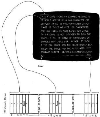
The image on a 480-character unit is displayed on 12 horizontal rows of 40 characters each (Figure 2-2). The image on a 1 ,920-character unit is displayed on 24 horizontal rows of 80 characters each.
.! u
E!
c
..c U
I
o
~
... :I:
CD
u
-
VI&.u.
VI
\~
\'
.~ CD ( )~~ Z 0
-
...
w) VI
(
\
\~o .- ('oj M "'o:t Ii') ---il ~I - -.. ~ ~ ~ ~ ~ ----ilt-I - - _ .. ~ :::: ~ ft
[image:21.615.213.559.49.452.2]"'o:t "'o:t "'o:t "'o:t
Figure 2-2. Relationship between Display Station Buffer and Character Position on Display Image Screen (Unformatted Display)
Unformatted and Formatted Display Images
An application program can communicate with a display operator by one of two basic
methods. In one method, the display screen is left unformatted and the display operator uses the screen in a free-form manner. In the second method, the display image is completely or partially formatted (organized or arranged) by the application program.
2-4
I~
' 4 - - - 8 0 Character Positions---.-'I.. I
---0 80 160 240 320 400 480 560 640 720 24 Rows 800 880Model 2 Unit Buffer (1,920 character positions) 960 1040 1120 1200 1280 1360 1440 1520 1600 1680
I·"
·1
.... - - - 40 Character Positions - - -. .
I 0 40 80 120 160 12 Rows 200 240 280 320 360 400 440
Modell Unit Buffer (480 character positions) 39 79 119 159 199 239 279 319 359 399 439 479
[image:22.612.62.459.43.661.2]Note: See Appendix 8 for hexadecimal equivalents.
Figure 2-3. Buffer Addressing Layouts for Model 1 and Model 2 Devices
[JNAME
:t:J JOHN B DOE
[]JOB
TITLE :[]WRITER
(] PHONE .,..: [] 383-7628
00 01 Hex 1 00 01 10 11 00 01 10 11 Bits
i
4567 0 1 2 3 4 5 6 7
0000 0 NUL SP & 0001 1 SBA /
0010 2 EUA
0011 3 IC
0100 4
0101 5 PT NL
0110 6
0111 7
1000 8
1001 9 EM
1010 A ¢ ! I I :
1011 B
.
$ #1100 C FF DUP RA <
.
% @1101 0 SF ( )
-1110 E FM + ; > = 1111 F SUB I ---, ?
..
Notes:
10
00 01 10 11
8 9 A B
--~ I a j I
-,I b k s
!
·
,
I C I t I
,
i
I d m u
·
I e n vi
Ii
f 0 Wi
l·
,!
9 P x1
: h q y -~i
i
i r z :.--
~-11 00 01
C 0
A J
B K
c L
0 M
E N F 0
G P H Q
I R 10 E 5 T U V W X y Z 11 F 0 1 2 3 4 5 6· 7 8 9 ~
...-Bits 0,1 2,3 Hex 01. Character code assignments other than those shown within all outlined areas of this chart are undefined. If an undefined character code is programmed, the character that will be displayed or printed is not specified. The character displayed by the 3277 or 3275 for a given undefined character code may be different for other devices. IBM reserves the right to change at any time the character displayed for an undefined character code.
2. Lowercase alphabetic characters (shown within the dotted outlined area) are converted to upper-case by the display station or printer and displayed or printed as upperupper-case characters.
3. NL, EM, FF, DUP, and FM control characters are displayed or printed as 59 < * and; char-acters, respectively, except by printers under format control, in which case NL and EM do not result in the printing of a character, and by printers successfully executing FF, in which case
< is not printed.
4. Bits 0 and 1 are assigned for the following characters: AID, attribute, write control (WCC), copy control (CCC), CU and device address, buffer address, sense, and status. Bits 0 and 1 are assigned so that each character can be represented by a graphic character within the solid outlined areas of the chart. See Figure 2-7.
5. This table also applies for Belgian, French, and Italian mono-case I/O interface codes and graphics.
6. The: character (hex 6A) is not displayed and is printed by the 3287 and 3288 only. 7. For BSC data-link control characters, see Chapter 5.
8. See Appendix C for Katakana EBCDIC codes. 9. See Appendix D for Data Analysis - APL codes.
10. See IBM 3270 Information Display System: Character Set Reference, GA27-2837, for all inter-face codes for the 3270 system.
2-6
Hex 1 000 001 010 011 Bits
~
4321 0 1 2 3
0000 0 NUL SP 0 0001 1 SBA ! 1 0010 2 EUA
..
2 0011 3 Ie # 3 0100 4 RA $ 4 0101 5 % 50110 6 & 6
0111 7 7
1000 8 ( 8
1001 9 PT EM ) 9
1010 A NL SUB
.
: 1011 B + ; 1100 C FF DUP , < 1101 0 SF - =1110 E FM > 1111 F I ?
Notes:
100 101 4 5
@ P A Q
B R C S 0 T
E U F V
G W H X I Y
J Z
K ( L \
M ) N " 0
-110 111
6 7
p
-.
-a q
b r
c s d t
I
e u f v 9 wI
h xJ
i y j z--k I
.
I m n 0 --'-Bits 4-7,6,5 .... HexO1. Character code assignments other than those shown within all outlined areas of this chart are
undefined. If an undefined character code is programmed, the character that will be displayed
or printed and the liD interface code returned on a subsequent read operation are not specified. The character displayed or printed by these terminals for a given undefined character code may
be different for other terminals. IBM reserves the right to change at any time the character
dis-played or printed and the liD interface code returned for an undefined character code.
2. Lowercase alphabetic characters (shown within the dotted outlined area) are converted to upper-case by the display station or printer and displayed or printed as upperupper-case characters.
3. NL, EM, FF, DUP, and FM control characters are displayed·or printed as 5 9 < * and;
characters, respectively, except by printers under format control, in which case NL and EM do not result in the printing of a character, and by printers successfully executing FF, in which case < is not printed.
4. AID, attribute, write control (WCC), copy control (CCC), CU and device address, buffer address,
sense, and status characters are assigned as specified in Figure 2-7 so that each character can be
represented by a graphic character within the solid outlined portion of this chart.
5. ASCII A option displays and prints I and -, for interface codes 21 and 5E. (hex), respectively.
ASCII B option displays and prints! and I\. for codes 21 and 5E (hex), respectively.
6. The FF control character (OC) Is returned to the host during a subsequent read operation as
46.
7. For BSC data-link control characters, see Chapter 5.
Display Fields
The control characters (dotted squares) shown in Figure 2-4 are constructed by the pro-gram. They define the characteristics or attributes of the data that follow them and are called attribute characters. Each attribute character plus all the data following it up to the next attribute character is called afield. When a field "wraps" the screen, the field continues from the last character location in the buffer to the first location in the buffer until it is terminated by an attribute character. Figure 2-4 shows eight fields. Figures 2-5,2-6, and 2-7 show the United States I/O interface codes used.
Organizing the display data into fields facilitates display operations for the program and for the operator. Fields are also used in most 3270 programming operations: functions that involve the storage, display, printing, or transmission of data are primarily field-oriented. Some operations performed on fields that wrap the screen are terminated by the last buffer address rather than by the field terminating attribute. This effect is noted in the deSCriptions of the specific operations.
Attribute characters, in addition to defining the start of a field, define the following field characteristics for all character locations contained in that field:
• Protected (from modification by a display operator) or unprotected (available for the operator to modify or enter data). The unprotected definition classifies a field as an input field.
• Alphameric (an input field in which an operator can enter alphabetic, numeric, or symbol characters) or numeric (has special meaning for protected fields, data entry keyboards, and the Numeric Lock special feature).
• Character display (nondisplay, display, intensified display).
• Detectable or nondetectable (by use of the selector pen).
• Tabstop positions (first character position of unprotected fields).
Each attribute character occupies one of the 480- or 1 ,920-character locations in the buf-fer, but it cannot be displayed or printed. During a display or a printout, its character location appears as a space. Figure 2-8 shows the bit definition for an attribute character.
Attribute characters are treated as characters that are protected from operator inter-vention; that is, they cannot be replaced by alphameric characters entered from the key-board or modified by use of the selector pen. However, the modified data tab (MDT) bit (7) of the attribute character can.be changed by an operator, as described in Figure 2-8. Also, attribute characters are not protected from being overwritten by alphameric data that is included in the data stream of a Write or Erase Write command. When the operator uses the CLEAR key, attribute characters and all characters in a formatted buf-fer are erased. See Chapter 7 for details of screen deSign. See Chapter 8 for screen management.
Bits 2-7 Graphic EBCDIC ASCII Bits 2-7 Graphic EBCDIC ASCII
00 0000 SP 40 20 10 0000
-
60 2000 0001 A Cl 41 10 0001 I 61 2F
00 0010 B C2 42 10 0010 S E2 53
00 0011 C C3 43
10 0011 T E3 54
00 0100 0 C4 44
00 0101 E C5 45
00 0110 F C6 46
10 0100 U E4 55
10 0101 V E5 56
00 0111 G C7 47 .JO 0110 W E6 57
00 1000 H C8 48 10 0111 X E7 58
00 1001 I C9 49 10 1000 Y E8 59
{
¢ 4A-00 1010
[ - 5B
00 1011 4B 2E
10 1001 Z E9 5A
10 1010 I (EBCDIC) 6A 7C
I
10 1011 , 6B 2C
00 1100 < 4C 3C 10 1100 % 6C 25
00 1101 ( 40 28 10 1101
-
60 5F00 1110 + 4E 2B
10 1110 > 6E 3E
{
I 4F-00 1111
! - 21 10 1111 ? 6F 3F
01 0000 & 50 26 11 0000 0 FO 30
01 0001 J 01 4A
11 0001 1 Fl 31
01 0010 K 02 4B
01 0011 L 03 4C
01 0100 M 04 40
11 0010 2 F2 32
11 0011 3 F3 33
01 0101 N 05 4E 11 0100 4 F4 34
01 0110. 0 06 4F 11 0101 5 F5 35
01 0111 P 07 50 11 0110 6 F6 36
01 1000 Q 08 51 11 0111 7 F7 37
01 1001 R 09 52 11 1000 8 F8 38
{
! 5A-01 1010
] - 50
11 1001 9 F9 39
11 1010 : 7A 3A
01 1011 $ 5B 24 11 1011 # 7B 23
01 1100 * 5C 2A 11 1100 @ 7C 40
01 1101 ) 50 29
01 1110 ; 5E 3B
01 1111
{
"I 1\ 5F-
5E11 1101 , 70 27
11 1110 = 7E 3D
11 1111 " 7F 22
Note: The characters above are used as attribute, AID, write control (WCC), copy control (CCC), CU and device address, and buffer address.
They are also used as status and sense. When any of these characters is transmitted to the program, the CU assigns the appropriate EBCDIC
code. If transmission is in ASCII, the CU translates the EBCDIC code to ASCII code prior to transmission.
To use this table to determine the hex code transmitted for an address or control character, first determine the values of bits 2-7. Select this
bit configuration from the UBits 2-7" column. The hex code that will be transmitted (either in EBCDIC or in ASCII) is to the right of the
bit configuration.
Use this table also to determine equivalent EBCDIC and ASCII hex codes and their associated graphic characters. See Note 5 of Figure 2-6
for ASCII A and B graphic character difference for ASCII codes 21 and 5E (hex).
Graphic characters for the United States I/O interface codes are shown. Graphic characters might differ for particular World Trade I/O
interface codes. Refer to IBM 3270 Information Display System: Character Set Reference, GA27-2837, for possible graphic differences when
these codes are used.
Figure 2-7. Control Character I/O Codes
Keyboard Operations
Attribute-Character Bit Assignments
x
o
EBCDIC Bit
o
2
3
4&5
6
7
U/P A/N D/SPD Reserved
2 3 4 5 6
Field Description
Value determined by contents of bits 2-7. See Figure 2-7.
Always a 1.
o
= Unprotected 1 = Protectedo
= Alphameric1 = Numeric (causes automatic upshift of data entry keyboard)
Note: Bits 2 and 3 equal to 11 causes an automatic skip. See text.
00 = Display/not selector-pen-detectable. 01 = Display/selector-pen-detectable.
10 = Intensified display/selector-pen-detectable. 11 = Nondisplay, nonprint, nondetectable.
Reserved. Must always be O.
Modified Data Tag (MDT); identifies modified fields during Read Modified command operations.
o = Field has not been modified.
1 = Field has been modified by the operator. Can also be set by program in data stream.
MDT
7
Note: Bits 0 and 1 are not decoded when received by the 3270. When characters are transferred to the CPU, bit 1 is a 1 and bit 0 is set (as shown in Figure 2-7), depending upon the character being transferred. All attribute characters are part of the defined character set. The default option (bits 2 through 7 al/ set to 0) results in an unprotected, alphameric, displayed, nondetectable field.
Figure 2-8. Attribute-Character Bit Defmition
Keyboards, which can be attached to a 3277 or 3275, enable the operator to change, edit, or create character displays except within fields, defined by attribute characters, as protected from keyboard operations by the program. As messages are being composed or modified by keyboard operations, the changes are inserted in the buffer and displayed on the subsequent display regeneration cycle.
Cursor
Keyboards
2-10
A special symbol (that resembles an underscore), called a cursor, is displayed beneath a character or character position on the display screen to indicate where the next character entered from the keyboard will be stored (Figure 2-2). For example, when the cursor is displayed under one character in a line of characters, that character can be changed or deleted by keyboard action. Also, if the cursor is displayed under a position without a display character, a character can be inserted in that position by keyboard action. All these operations, when performed on a formatted display, cause the MDT bit (7) of the attribute character for the field to be set to 1. However, when the cursor appears beneath a character in a protected field or an attribute character, that position cannot be modified by keyboard action, and the MDT bit is not set.
One, and only one, cursor is always displayed on the display. A cursor check occurs when the display station circuitry detects no cursor or more than one cursor in the buffer. When the display is turned on, the cursor is automatically generated and dis-played in the first location on the screen. The cursor can be repositioned by the key-board operator and also by the program. The cursor is not affected by field attributes or by the Key Lock special feature; it is displayed even when positioned in a nondisplay
i
non print field and when the Key Lock special feature (if installed) is turned off.Four types of keyboards are available for the 3277 and 3275 Display Stations: type-writer, data entry, data entry-keypunch layout, and operator console keyboard. All keyboards have special symbol keys and control keys for entering data. The type of keyboard determines the characters and symbols that can be key-entered from the display station, but does-not determine which type of characters and symbols can be transmitted from the system for the display image.
Variations between keyboards include 66-key and 78-key versions. The 66-key keyboard provides all the basic operator keys. The 78-key keyboard provides expanded operator-to-program message flexibility with 12 additional keys that may be defined to fit the requirements of the application program. The four basic types of keyboards, shown in Figure 2-9, are defined below. Refer to the IBM 3270 Information Display System:
Character Set Reference, GA27-2837, for World Trade (WT) keyboard key layouts and nomenclature.
Typewriter Keyboard: This keyboard provides the basic typewriter key layout. Alphameric keys are encoded with both lowercase and uppercase codes. The typewriter keyboard is available with program-function keys PFI through PF12 (78-key version) or without (66-key version).
Data Entry Keyboard: This keyboard provides the basic data-entry type of key layout. When characters are entered in a numeric field, the keyboard is automatically upshifted to take advantage of the grouped numeric keys (bold-outlined in Figure 2-9). The data entry keyboard contains 66 keys, including program-function keys PFI through PF5.
Data Entry Keyboard-Keyboard Layout: This keyboard has the same keys and features as the data entry keyboard. The key layout of this keyboard more closely resembles the layout of the 29 Card Punch and 129 Card Data Recorder. In many cases the layout is identical with that of the keypunch units except for function-key designations. This keyboard is recommended for data entry applications.
8) -
Typamotk Key>0 -
Nu .... "" Kev.Typewriter Keyboard (EBCDIC) - The ASCII typewriter keyboard, which accommodates both ASCII-A and ASCII-B character set options, has four different keys, shown above keyboard.
Data Entry
Data Entry - Keypunch Layout
Operator Console
Key Functions
2-12
Alphameric character keys encompass the complete 63-character EBCDIC and 64-character ASCII 64-character sets (as shown within the bold outline in Figures 2-5 and 2-6, respectively), including Space.
Alphabetic characters can be entered into the display buffer in either uppercase or lower-case code, depending upon the position of the SHIFT key, from the typewriter or operator console keyboard. Only uppercase alphabetic codes can be entered from the data entry keyboards. All alphabetic characters in the buffer (uppercase or lowercase codes) are displayed as uppercase characters.
Keyboard entry of an alphameric character into the display buffer occurs at the cursor location, provided the cursor is located in an alphameric character location within an unprotected data field. (An attempt to enter an alphameric character into a protected data field or into an attribute character location is blocked.) Successful keyboard entry of the alphameric character causes the cursor to advance to the next character location within the unprotected data field.
Automatic-Skip: Upon entry of a character into the last character location of an unpro-tected data field, the cursor is repositioned according to the attribute character describing the next field.
If the attribute character defines the next field as (1) alphameric and either unprotected or protected, or (2) numeric and unprotected, the cursor skips the attribute character and is positioned to the first character location in that field.
If the attribute character defines the field as numeric and protected, the cursor auto-matically skips that field and is positioned to the first character location of the next unprotected field.
Character-Oriented Keys: A cluster of four keys (located to the right of the main key-board) moves the cursor one location at a time into any character location:
t
(up),-1-(down), -+(right), and -f-(left). A fifth key, the backspace key, occupies its normal position on the main keyboard. It is also designated by -f- and performs the same functions as the move-cursor-left key. The cursor may be moved into any character location, including unprotected and protected alphameric character and attribute character locations, through the use of these keys. Operation of these keys does not affect the MDT bit.
These keys are all capable of causing the cursor to wrap. Horizontal wrap always involves a vertical movement; the cursor repositions to the next or preceding row of characters. Vertical wrap due to operation of the up or down keys involves no horizontal movement: the cursor stays in the same character column.
These keys all have typamatic operation at a repeat rate of approximately 10 operations per second. (When a typamatic key is fully pressed, its function is repeated as long as the key is held pressed.)
Field-Oriented Keys: Any of four keys moves the cursor to the first position in a field. All four key operations can cause the cursor to wrap from the end of the last line on the display and to continue at the beginning of the top line. Operation of these keys does not affect the MDT bit.
-+1 (Tab) Key: Moves the cursor to the first character location of the next unprotected
~ (Backtab) Key: When the cursor is located in the attribute character or the first
alphameric character location of an unprotected data field or in any character location of a protected data field, this key moves the cursor to the first alphameric character location of the first preceding unprotected data field. When the cursor is located in any alpha-meric character location of an unprotected data field other than the first location, this key moves the cursor to the first alphameric character location of that field. In a display with no unprotected fields, the cursor is repositioned to character location O. The Backtab key has no typamatic capability.
+-I (New Line) Key: Moves the cursor to the first unprotected character location of the
next line. If the display has no unprotected data fields, the cursor is repositioned to character location O. If the display contains no fields, the cursor is repositioned to the first character position of the next line. The New Line key has typamatic capability at a rate of approximately 10 operations per second.
SKIP Key (Data Entry Keyboards Only): Performs the same functions as the Tab key.
ERASE EOF (Erase to End of Field): If the cursor is located in an alphameric character location in an unprotected data field, this key clears the character location occupied by the cursor, and all remaining character locations in that field, to nulls. The operation can wrap from the end of the last line on the display to the beginning of the top line. The cursor does not move as a result of operating this key, and the MDT bit is set to 1.
Operation of this key when the cursor is located in an attribute character location or is within a protected data field disables the keyboard; no character locations are cleared, the cursor is not moved, and the MDT bit is not set.
ERASE INPUT Key: This key clears all unprotected character locations to nulls, resets the MDT bit to 0 in unprotected fields, and repositions the cursor to the first unprotected character location on the screen.
In a buffer with only protected data fields, no character locations are cleared and the cursor is repositioned to character location O.
If the display contains no field, the entire buffer is cleared to nulls and the cursor is repositioned to location O.
INS (Insert) MODE Key: This key lights the INSERT MODE indicator and places the keyboard controls in an insert mode of operation, regardless of the cursor location.
If the cursor is located in an unprotected data field having a null character either in the character location identified by the cursor or in any character location in the field beyond the cursor, operation of an alphameric key causes that alphameric character to be entered at the cursor and the MDT bit to be set to 1. The character formerly occupying the cursor location and all remaining characters within the field (except for null
characters or characters to the right of null characters) are shifted one character location to the right. If the location identified by the cursor location at the time of the insert operation is a null, no character shifting occurs.
2-14
If more than one row of characters is contained within the field, a character occupying the last character location in the row is shifted into the first character location of the next row.
Operating an alphameric key in insert mode when the cursor is located in an attribute character location or is within a protected data field disables the keyboard; no character locations are cleared, the cursor is not moved, and the MDT bit is not set.
Operation of the RESET key returns the keyboard to normal mode.
DEL (Delete) Key: If the cursor is located in an alphameric character in an unprotected field, operation of the DEL key deletes the character from the character location occupied by the cursor and sets the MDT bit to 1 (if it has not previously been set). The cursor does not move. All remaining characters in the unprotected field, to the right of the cursor and on the same row, shift one character location to the left. Vacated character locations at the end of the row are filled with nulls. If the unprotected field encompasses more than one row, characters in rows other than the row identified by the cursor are not affected.
Operating this key when the cursor is located in an attribute character location or is within a