Systems Reference Library
IBM 1447 Console
This reference publication contains a detailed description of all models of the IBM 1447 Console.
Indicator lights, keys, dials and switches are described, as well as operation of the console I/O printer. Specific models of the IBM 1447 Console can be
attached to the following systems:
IBM 1240 Bank Data Processing System IBM 1401 Data Processing System IBM 1440 Data Processing System [BM 1460 Data Processing System
The required and available special features, including the IBM 1050 components, are also discussed.
Programming considerations for the 14:47, when used with a 1050 system, are also included.
Major Revision, December 1964
This SRL publication, A24-3031-3, is a major revision of, and obsoletes, A24-3031-2.
Contents
IBM 14.:1~7 Console, Modell ... "... 5
Indicator Light Panel... ... ... ... ... 5
Operating Panel ... "... 9
IBM 1447 Console, Model 2 ... 15
Console I/O Printer ... 15
Console Printer Operation ... 18
IBM 1447 Console, Model 3 ... 22
IBM 14.:1~7 Console, Model 4 ... 23
IBM 1026 Transmission Control Unit ... 24
Special Features ... 25
Sense Switches (Models 1, 2, 4) ... 25
Pin-Feed Platen (Models 2, 3, 4) ... "... ... 25
1051 Modell Attachment ... 25
Buffer Feature ... ... ... .... 27
Remote-Terminal Attachment Feature (Unbuffered) ... 30
Remote-Terminal Attachment Feature (Buffered) ... 32
Programming Considerations ... 37
Programming Routine ... "... 37
Programmed Write to a Terminal ... "... 37
Polling and Receiving Operation ... "... 38
General Information, Remote-Terminal Attachment Feature ... 40
1447 Printer Keyboard Polling ... 40
Longitudinal Redundancy Check (LRC) ... 41
Programming, Remote-Terminal Attachment Feature ... ... 41
Remote-Terminal Operations ... "... 41
Addressing Operation ... "... 42
Error Conditions and Condition Indicators ... ... ... 42
Remote 1050 Functions ... 43
Line-Control Characters ... "... 43
Sample Program Loop for Troubleshooting... 44
.
~ I • • " • • ••
ElBlE;: . . .
[image:4.612.47.416.63.355.2]a
;
•
it•
!i!!.
••
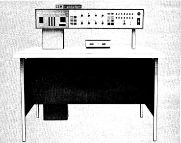
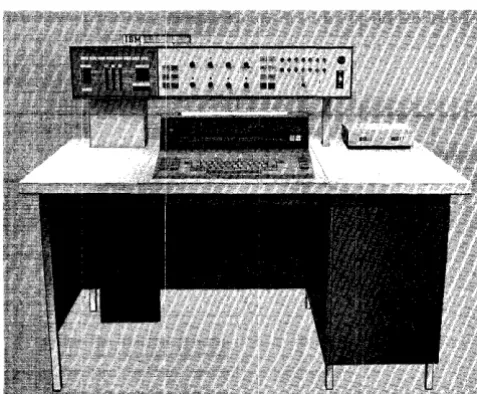
~The IBM 1447 Console, Modell, can be attached to
the IBM 1240, 1440, or 1460 systems.
The 1447 Modell (Figure 1), containing operating keys, lights, and switches, i.s designed to give the operator external control for setting up and checking system operation. Several features facilitate program testing.
The left side of the console panel shows the data as it moves from one system component to another (address registers, character registers, and storage addresses).
Special lights indicate operating conditions of the processing and disk units, the card read-punch, and the printer. If certain errors are detected while the system is running, a red light on the console comes on to show which unit requires attention.
The operator can display the contents of any storage location and control the course of program execution by setting sense switches in an ON or OFF position, if
the program has been designed to take advantage of this flexibility.
The main power supply for the system is controlled by switches on the console. A special switch discon-nects all power from the system in case of emergency.
A mode switch facilitates machine operation and program testing by permitting:
1. Single··cycle operation for detailed examination of progra.m functions.
2. The displa.y of the contents of a particular storage area.
3. The manual change of the contents of any address register or storage location.
4. The contents of storage to be printed with word-mark identification.
5. The scanning of storage for invalid characters. 6. The operator to stop execution of the program at a
predetermined point. This provides an opportunity to bypass program steps that have already proved accurate and to stop at instruction areas that need to be examined step by step.
IBM 1447 Console, Model 1
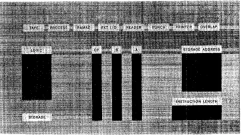
Indicator Light Panel
The indicator light panel (Figure 2) uses back-lighting to display data. The bit configuration of each character in each logical element is shown in binary-coded deci-mal form (including the check-bit status in all ele-ments and the word-mark status in all eleele-ments but the Op register). The data is displayed one character at a time. A parity or validity check condition at any dis-play location is indicated by a red light in the legend directly above the character display that caused the check condition.
Some IBM 1447 Console lights and controls pertain
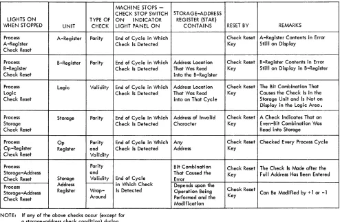
to specific models or special features. These are listed in the order shown on the operating panel.. The parity and validity check conditions that turn on some of the lights on the indicator light panel are shown in Fig-ure 3.
Tape Light
This light comes on whenever a tape-check condition occurs during a tape-read or tape-write operation. The check condition also turns 011 the tape-transmission
error indicator. The status of this indicator must be tested by a BRANCH IF TAPE TRANSMISSION ERROR INDI-CATOR ON instruction - B (III) L. The indicator and
the associated light are reset off by the next tape read or write operation.
[image:5.612.330.571.560.695.2]MACHINE STOPS -CHECK STOP SWITCH
LIGHTS ON TYPE OF ON INDICATOR
WHEN STOPPED UNIT CHECK LIGHT PANEL ON
Process A-Register Parity End of Cycle in Which
A-Register Check Is Detected
Check Reset
Process B-Register Parity End of Cycle in Which
B-Register Check Is Detected
Check Reset
Process Logic Validity End of Cycle in Which
Logic Check Is Detected
Check Reset
Process Storage Parity End of Cycle in Which
Storage Check Is Detected
Check Reset
Process Op Parity End of Cycle in Which
Op-Register Register and Check Is Detected
Check Reset Validity
Process Parity
Storage -Address and
Check Reset Storage Validity End of Cycle
Process Address in Which Check
Storage-Address Register Wrap- Is Detected
Check Reset Around
NOTE: If any of the above checks occur (except for a storage-address check condition) during an I/O operation, that operation is completed before. the system stops.
Figure 3. Processing-Unit Check Conditioning
The light is also turned on if the tape-select switch is not in the N-position, or if a tape drive is selected but not ready.
Process Light
This light and its associated process-check indicator turn on whenever a process-check condition occurs in the processing unit. This condition also stops the sys-tem when the check-stop switch is on. The light and the process-check indicator are reset off by pressing the check-reset key. System operation is resumed by pressing the start key.
The process light also comes on whenever a process-check condition occurs in the processing unit and the check-stop switch is off. The process-check indicator is also turned on, but the machine does not stop. The light remains on until it is turned off either by pressing the check-reset key or executing a BRANCH IF PROCESS CHECK INDICATOR ON (with check-stop switch off) in-struction - B (III) %. The process-check indicator re-mains on until this branch operation is executed.
STORAGE-ADDRESS REGISTER (STAR)
CONTAINS RESET BY REMARKS
Check Reset A-Register Contents in Error Key Still on Display
Address Location Check Reset B-Register Contents in Error That Was Read Key Still on Display in B-Register into the B-Register
Address Location Check Reset The Bit Combination That That Was Read Key Causes the Check Is in the into on That Cycle Storage Unit and Is Not on
Display in the Logic Area. Address of Invalid Check Reset A Check Indicates That an
Character Key Even-Bit Combination Was
Read into Storage
Any Check Reset Checked Every ProCI~ss Cycle
Address Key
Bit Combination Check Reset The Check Is Made Ilfter the That Caused the Key Full Address Has BeE!n Entered Error
Depends upon the
Operation Being Check Reset Can Be Modified by + 1 or -1 Performed and the Key
Modification
This light cannot be turned off by a BRANCH instruc-tion - B (III) % if either the Op light or the storage-address light is on. These errors indicate conditions in the program or the CPU, beyond which correct proc-essing is unlikely.
RAMAC® Light
This light comes on whenever a check condition occurs in one of the IBM 1301 Disk Storage or 1311 Disk Stor-age Drives. An associated check indicator in the proc-essing unit is also turned on. The light and its associ-ated check indicator are turned off either by pressing the start-reset key or when the next disk-storage in-struction is executed.
Ext I/O Light (ExternallnputIOutput)
[image:6.612.54.548.62.384.2]when the condition requiring attention is satisfactorily corrected. Refer to the appropriate Systems Reference Library publication for the external input/output unit concerned.
Reader Li~1ht (124011440)
This light comes on when:
1. The reader is selected but not ready. 2. A read register check occurs. 3. A reader validity check occurs.
4. A reader or punch validity check occurs.
*
Reader Lil~ht (1460)
This light comes on when:
1. The reader is selected but not ready (stacker full, read-feed jam or feed failure, or £Ie-feed delay). 2. A reader-check (hole-count) error occurs. 3. A reader-validity error occurs.
Punch Light (124011440)
This light comes on when:
1. The punch is selected but not ready (stacker full or jam).
2. A punch-validity error occurs. 3. A punch error occurs.
*
4. A punch check error occurs.*
The items indicated. by an asterisk under the headings Reader Light (l2~W/1440) and Punch Light (124011440) refer to ma-chines manufactured before Feb. 29, 1964.Punch Light (1460)
This light comes on when:
1. The punch is selected but not ready (out of cards, stacker full, or punch-feed jam).
2. A punch-check (hole-count) error occurs.
Printer Li~1ht
This light comes on when:
1. The printer is selected but not ready. 2. A printer error occurs.
Note: The reader, punch, and printer lights on the console in-dicate the system area in error. If the machine stop was caused by a functional condition (out of cards, forms jam, etc.), oper-ator attention will be required at the unit giving the trouble.
If the machine stop (110 check-,stop switch on) was caused by an operational condition (print check, validity, etc.), the error light can be turned off with the check-reset key on the 1447 console. System operation is resumed by pressing the unit start key.
If the 110 check-stop switch is off, the console error light will remain on until a branch on an 110 error instruction is executed.
Reader error branch d-modifier ? Punch error branch d-modifier I Printer error branch d-modifier :/:
Depending on which CPU the 1447 is attached to, it may be necessary to press the reset key on the system unit causing the stop.
Overlap Light (1460)
During an overlap cycle, this light comes on whenever a process-check condition occurs in the processing unit. The system stops when the check-stop switch is on. Ordinarily, the process light is also on, indicating the type of failure. If an A-register check condition occurs during a tape-overlap cycle, however, only the overlap light comes on. It remains on until either the check-reset key is pressed or a BRANCH IF PROCESS CHECK INDICATOR ON (with check-stop switch off) instruction
- B (III) % is executed. The system is restarted by pressing the start key.
Logic Light
This light comes on when a check condition occurs during the cycle used to store the adder output. The system also stops if the check-stop switch is on. The light remains on until the check-reset key and the start key are pressed to restart the system.
OVF (Overflow) Light
This light, below the logic light, comes on when an arithmetic overflow condition occurs in the machine. The overflow condition also turns on an overflow indi-cator. Both the light and the indicator remain on until the status of the indicator is tested by a BRANCH IF OVERFLOW INDICATOR ON instruction - B (III) Z. Exe-cuting this branch instruction turns off both the light and the indicator.
B
¥=
A Lightthis indicator can be tested by a BRANCH IF UNEQUAL COMPARE INDICATOR ON instruction - B (111)/. The
light and the indicator remain on until they are turned off by either the next compare or the next disk-storage operation.
B = A Light
This light, below the logic light, comes on when the B-field and the A-field contents are equal during a compare operation, or when the addresses are equal during a disk-storage address-compare operation. These equal conditions also turn on the equal-compare indicator. The status of this indicator can be tested by a BRANCH IF EQUAL COMPARE INDICATOR ON instruction
- B (III) S. The light and the indicator remain on until they are turned off by the next compare operation or the next disk-storage operation.
B
>
A LightThis light, below the logic light, comes on when the value of the B-field is greater than the value of the A-field, or when the A-field is shorter than the B-field (during a compare operation), or when the address in storage is the greater address during a disk-storage address-compare operation. These conditions also turn on a high-compare indicator. The status of this indi-cator can be tested by a BRANCH IF HIGH COMPARE INDICATOR ON instruction - B (III) U. The light and
the indicator remain on until they are turned off by the next compare operation or the next disk-storage op-eration.
B
<
A LightThis light, below the logic light, comes on when the value of the B-field is less than the value of the A-field (during a compare operation), or when the sector ad-dress on the disk is the greater adad-dress during a disk-storage address-compare operation. These conditions also turn on the low-compare indicator. The status of this indicator can be tested by a BRANCH IF LOW COM-PARE INDICATOR ON instruction - B (III) T. The light
and the indicator remain on until they are turned off by the next compare operation or the next disk-storage operation.
Bit-Display Lights
At the end of a B-cycle, these lights display the bit configuration of the sum of the characters being proc-essed in the arithmetic operation.
Storage Light
This light comes on when a character is read into core storage and a parity-check condition occurs .. The light remains on until it is turned off by pressing the check-reset key. The system is restarted by pressing the start key.
Op (Operation Register) Light
This light comes on when the operation register de-tects that the character in the register is an incorrect (invalid) operation code. The light blocks below this light indicate the BCD coding and the check-bit status of the character in the operation register. The light remains on until it is turned off by pressing the check-reset key. This light cannot be check-reset by the PROCESS CHECK TEST BRANCH instruction - B (III) %.
B (B-Register) Light
This light comes on when the B-register detects that the character in the register is of incorrect (even-bit) parity. The light blocks below this light indicate the BCD coding and the check-bit and word-mark status of the character in the register. The light remains on until it is turned off by pressing the check-reset key.
A (A-Register) Light
This light comes on when the A-register detects that the character in the register is of incorrect (even-bit) parity. The light blocks below this light indicate the BCD coding and the check-bit and word-mark status of the character in the register. The light remains on until the check-reset key is pressed.
Storage-Address Light
This light comes on when the storage-address register detects that one or more characters in the register are of incorrect parity or that the address in the register is invalid. The light blocks below this light display the address characters that caused the check condition. The light remains on until the check-reset key is pressed. This light cannot be reset by the PROCESS CHECK TEST BRANCH instruction - B (III) %.
Instruction-Length Lights
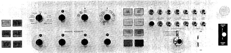
Figure 4. Operating Panel on the IBM 1447 Console
Operating Panel
The operating panel (Figure 4) contains the keys, lights, switches, and dials used by the operator to con-trol the system. Some IBM 1447 lights and controls pertain only to certain models, or are used with certain special features.
O-Add Reg Key (1460)
The O-address register key light is used in conjunction with the Processing Overlap special feature. The key is lighted when pressed. It displays the O-address reg-ister contents in the storage address indicator lights.
When processing stops at the end of an individual cycle involving the overlap feature, the key is lighted and the storage-address block shows the address of the last character read out from (or read into) core stor-age in the overlap mode.
The O··address register key light may turn on at the same time as any other address-register key lights. Pressing any address-register key light turns off the O-address register key light:, and pressing this key light turns off any other key light.
I-Add Reg Key
This key is lighted when pressed. It displays the 1-address register contents in the storage-1-address indi-cator lights. If the system stops during an 1- (instruc-tion) cycle, I-ADD BEG remains lighted and the
storage-address indicator lights display the last I-storage-address that addressed core storage.
A-Add Reg Key
This key is lighted when pressed. It displays the A-address register contents in the storage-A-address indi-cator lights. If the system stops during the A-portion of an E- (execution) cycle, A-ADD REG remains lighted
and the storage-address indicator lights display the last A-address that addressed core storage.
B-Add Reg Key
This key is lighted when pressed. It displays the B-address register contents in the storage-B-address indi-cator lights. If the system stops during the B-portion of an E- (execution) cycle, B-ADD REG remains lighted
and the storage-address indicator lights display the last B-address that addressed core storage.
A-Aux Reg Key
This key is lighted when pressed. It displays the A-auxiliary register contents in the storage-address indi-cator lights. The A-auxiliary register is part of the multiply-divide special feature. If the system stops during the A-auxiliary portion of an E- (execution) cycle, A-AUX REG remains lighted and the
storage-address indicator lights display the last A-auxiliary address that addressed core storage.
B-Aux Reg Key
This key is lighted when pressed. It displays the B-auxiliary register contents in the storage-address indi-cator lights. The B-auxiliary register is part of the multiply-divide special feature. If the system stops during the B-auxiliary portion of an E- (execution) cycle, B-AUX REG remains lighted and the
storage-address indicator'lights display the B-auxiliary storage-address that addressed core storage.
Manual Address
[image:9.612.76.557.70.182.2]with-out disturbing the contents of the address registers. These switches are eHective only when the mode switch is set to one of these positions:
l. Address Stop 2. Alter
3. Character Display 4. Storage Printout 5. Storage Scan.
Mode Switch
The mode switch selects the nine modes of machine operation.
Run. When the mode switch is set to RUN, the system
operates under stored-program control.
Address Stop. When the system is operating in this
mode, program execution stops when the program arrives at the core-storage address specified by the manual address switches. This switch setting is commonly used in program-testing operations. Pro-gram execution stops at the specific address of an instruction in the program, except for input or out-put operations.
1/ EX. When the mode switch is set to I/EX
(Instruc-tion/Execution), the system reads out one complete instruction from core storage when the start key is pressed, and then stops. This is called the instruc-tion phase.
When the start key is pressed again, the system executes the instruction previously read out, and then stops. This is called the execution phase.
Subsequent start-key operation results in the sys-tem initiating alternate instruction and execution phases. When an operation does not require an exe-cute phase, the next phase is the I-phase associated with the next instruction.
Single-Cycle Process. When the system is operating
in this mode, each start-key operation causes the system to execute one storage cycle and advance through the instruction or execution cycles of the program one character (storage cycle) at a time. (All execution cycles of an I/O operation are executed at one time.) The mode switch may not be moved from the SINGLE CYCLE position if the system is at
I -op of a CONTROL CARRIAGE instruction, or at 1-5 of a BRANCH IF CARRIAGE OVERFLOW instruction.
Single-Cycle Non-Process. When the system is
oper-ating in this mode, each start-key operation causes the system to execute a modified storage cycle and advance through the instruction or execution cycles of the program one character (storage cycle) at a time. The normal storage-cycle operation is modified
so that no data enters core storage from the A-register or from the logic unit. The data enters core storage from the B-register only. This mode of op-eration allows the system operator to observe arith-metic operation results, one character at a time, in the logic-display lights without altering the original B-field data.
Storage Scan. When the mode switch is set to STOR-AGE SCAN, holding down the start key causes the
system to start reading data out of the core storage, beginning at the address set in the manual address switches, and continuing until the start key is re-leased. If a character of incorrect parity is detected in core storage, the system stops and the check light associated with the check condition turns on. The address of the core-storage position that contains this character is displayed in the storage-address display lights. The B-register displays the contents of the core-storage position that caused the check condition.
Storage Printout. When the system is operating in
this mode, a block of core storage is printed. The
IBM 1403 can print a block of either 100 or 132
charac-ters. The IBM 1443 can print a block of either 120
or 144 characters. The two high-order manual ad-dress dial switches select the desired block of stor-age. The two low-order switches must be set to 01, unless the system is equipped with the print-storage special feature. The system interlocks if the two low-order address switches are not set to 01 and the system is not equipped with print storage.
Pressing the start key initiates the printout opera-tion. After the line is printed, an automatic print cycle prints one on the line below and in the
posi-tions corresponding to those that contain word marks. If additional print outs are required, the new (initial) core-storage address must be placed in the manual address switches.
The manual-address dials and the start key must be left undisturbed while a storage printout opera-tion is in progress.
A storage error occurs if an attempt is made to print out the last 100-band of storage on a 1440 or 1460 system. If this information is required, it must be moved to another area of core storage, using a series of load Op commands.
Char Display. When the mode switch is set to CHAR DISPLAY (Character Display), pressing the start key
initiates a B-register display of the contents of the core-storage address specified by the manual address switches. This operation does not alter the 1-, A-,
and B-address registers.
printout on the console I/O printer of the contents in core storage, beginning with the address set in the manual address switches. In this operation, word marks are printed as inverted circumflexes preceding the characters with which they are associated. The operation is stopped by pressing the stop key on the console. The stop key must be pressed before the start key is pressed.
Alter. VVhen the mode switch is set to ALTER, the
operator can manually change the contents of the 1-,
A-, or B-address register or any core-storage posi-tion. To change the contents of an 1-, A-, or B-ad-dress register, the operator must:
1. Set the manual address switches to the desired address.
2. Press the appropriate address-register key light. 3. Press the start key. The selected address register
should indicate the new address.
To change the contents of a specific core-storage position, the system operator must:
1. Set the manual address switches to the desired core-storage address.
2. Select the bit configuration desired with the char-acter-select dial.
3. Operate the enter key to enter the selected bit configuration with or without a word mark. The contents of adjacent core-storage positions can be changed by initiating an alter-pIus-one mode of operation when the mode switch is set to ALTER.
Once the alter-pIus-one mode is set up, the core-storage address automatically advances by plus one at the end of each alter cycle.
To set up an alter-pIus-one mode of operation, the system operator must:
1. Set the manual address switches to the desired core-storage address.
2. Press the B-address register key light. 3. Press and hOild the start key.
4. Operate the enter key.
5. When the enter key returns to its neutral position, release the start key.
The system is now ready to operate in its alter-plus-one mode.
To enter the new characters in the desired core-storage positions, the system operator must: 1. Select the bit configuration desired with the
char-acter-select dial.
2. Operate the enter key to enter the selected bit configuration with or without a word mark.
Tape Select
During programmed operation, this dial is set to N
(normal position). To select a particular tape unit for a manual operation, such as backspacing, set this switch to the number that corresponds to the tape unit.
Note: See Tape Load and Diagnostic Switch
sec-tions.
T ape Density (1460)
This three-position dial controls the low- and high-density rates of the IBM 72H Magnetic Tape Units, Models Vand VI, attached to the 1460 system. The three settings are 200-556, 200-800" and 556-800. The tape unit assumes the recording density designated by the switch.
The IBM 729 II, 729 IV, and 7330 Magnetic Tape Units operate at either 200 or 556 characters per inch regardless of the setting of the tape-density switch.
Auxiliary Mode (1460)
This dial can be set to anyone of six positions.
Off.
This is the normal setting. In this position, theswitch has no effect on system operation.
Full Storage Print. This position is used, in
conjunc-tion with the mode switch, to print the contents of all storage positions. When the mode switch is set to
STORAGE PRINT OUT and the start key is pressed,
print-ing starts with core-storage position 001 and con-tinues until all core-storage positions are printed. Word marks print as ones under the corresponding
data positions during the following print operation. A block of 132 characters is printed. However, the last 32 positions printed on each line are repeated at the beginning of the next line of elata. For ex-ample, core-storage positions 101-132 print at the end of the first line and at the beginning of the second line.
Print-Storage Scan. This position is used., in
conjunc-tion with the STORAGE SCAN setting of the mode
switch, to scan the standard print area in core stor-age (positions 201-332) and the 132 special print-storage positions. When the mode switch is set to
STORAGE SCAN and the start key is pressed, scanning
If an error is found in either register, the scanning operation stops. Otherwise, it stops at position 332. After an error stop, resetting the error indication and pressing the start key continues the scan opera-tion.
The other three positions of this switch prevent input! output operations from being performed in the overlap mode. These positions are used primarily by IBM Customer Engineers.
Tape I/O. This switch setting prevents magnetic tape or serial input/output operations from being per-formed in the overlap mode.
R/P. This switch setting prevents card (Read/Punch) operations from being performed in the overlap mode.
Tape I/O R/P. This switch setting prevents tape, serial input/output, or card operations from being performed in the overlap mode.
Sense Switch A
Sense switch A is a standard feature. It controls last-card operations by making a BRANCH IF INDICATOR ON
(d-character A) instruction cause a branch operation when the last card in the reader has passed the reading station.
The six additional sense switches (B, C, D, E, F, and G) are available (special feature).
Emergency-Off Switch
In an emergency, pulling this switch disconnects all power within the system. The switch must be manually reset by a Customer Engineer before power can be restored to the system.
Start-Reset Key
This key resets the system so that the operator can initiate a restart. It does not reset the inquiry channel
(if buffered), the address registers, or core storage. The inquiry channel is reset by pressing the type key and the start-reset key simultaneously.
N ate: The system must be stopped before the start-reset key is pressed.
I/O Check-Stop Switch
When this switch is on, the system stops at the com-pletion of any input or output operation in which a check condition was detected. When this switch is off, the system does not stop, and all check-condition de-tection must be accomplished by executing the appli-cable BRANCH IF INDICATOR ON instruction.
Check-Stop Switch (Process)
When this switch is on, the system stops when a proc-essing-unit check condition is detected. When the switch is off, the system stops for a processing-unit check condition only when the Op register, one of the address registers, or an input/output operation is involved.
I/O Check-Reset Switch
This switch resets check conditions sensed in an I/O unit when the I/O check stop switch is off. It is used primarily by Customer Engineers.
Diagnostic Switch
When this switch is on, characters are read into core storage just as they appear on the disk or tape record, without parity-correction. If a character having in-correct parity is transferred into core-storage, the system stops. The B-storage address register shows the storage location of the error, and the B-register displays the error character as it was read from the disk or tape.
When this switch is off, the parity of all data charac-ters is corrected (by the addition or deletion of a C-bit). This does not mean the character is now accurately transferred as it was originally written on the disk. A programmed operation (BRANCH ON ERROR instruction)
must be performed to determine if the disk record was satisfactorily read.
This switch may be used to find the character(s) in error, as follows:
l. Turn the diagnostic switch on. 2. Set the mode switch to I/EX.
3. Read in the suspected record under program con-trol.
4. Turn the mode switch to STORAGE SCAN. Press the
start key to scan core storage to the parity error. 5. If an error existed in the record, the system will stop. The address of the error will be shown in the B-storage address register. The B-register will dis~
play the contents of the error location.
6. The error can now be corrected at the discretion of the operator. Note: More than one core-storage position may be .in error.
7. Restore all controls to normal. If the error has been satisfactorily corrected, or if the error position was of no consequence to the program being run, the job can be restarted at this point. Note: The parity must have been corrected.
Disk-Writ,e Switch
The disk-write switch, by preventing the writing of test data on permanent records in disk storage, facili-tates program testing on any system equipped with disk storage. When the switch is on, all normal disk-storage operations can be performed.
When the switch is off, all disk-storage instructions except WRITE DISK and WRITE DISK WITH WORD MARKS are performed normally. When these instructions are encountered in a stored program, the OFF position prevents the data transfer from core storage to disk storage. The automatic comparison between the record address in core storage and the address on the disk record is performed, however, and the unequal-ad-dress-compare indicator turns on if an unequal con-dition occurs.
Note: A WRITE DISK CHECK instruction must be
per-formed following a write operation, regardless of the disk-write switch setting. Since the record data in core storage is not written on the disk when the switch is off, a check condition occurs during the following write-disk operation.
Lamp-Test Switch
Operating this switch turns on all the IBM 1447 Con-sole lights for a visual check of lamp circuits. Do not operate this switch while a job is in progress.
Tape Load (1240/1,440)
This key is used to load a program stored on tape, into core storage.
When the tape-load key is pressed, the tape unit specified. by the tape-select dial is selected, and the tape data starts entering core storage at position 001. The operation continues until an interrecord gap (IRG) is sensed. Then an a.utomatic branch back to core-storage position 001 occurs, and the instruction beginning in position 001 is executed.
The setting of the tape-select dial has priority over any programmed tape operations. For example, al-though a program can be loaded from any tape unit (selected as either 1 or 2), subsequent programmed tape operations will affect the tape unit whose address matches that set by the tape-select dial.
A programmed halt should follow a tape-load op-eration. This allows the operator time to reset the tape-select dial to the N-position.
Tape Load (1460)
The tape-select dial must be set to the N position. Tape-unit 1 is automatically selected. The program loaded from the tape begins in core-storage location 001. When the IRG is read, the program executes in-structions, starting at location 001.
Backspace (Tape)
When the tape-select dial is set for a specific unit, pressing this key backspaces the tape in the specified tape unit until an interrecord. gap is reached.
Type Key Light (Model 2 or 4)
The type key light used with the IBM 1447 Model 2 contains both a white and a red light. The white light glows when the console I/O printer is selected to oper-ate. The red light glows when the inquiry-clear indi-cator turns on. (The light turns off when the indiindi-cator is reset off.)
The operation that results from pressing the type key depends upon the mode of system operation. \Vhen the system is operating in:
l. RUN, pressing the type key sets the inquiry-request (Q) latch on.
2. CHAR DISPLAY, pressing the type key initiates an I/O printer print out of core storage, beginning at the core-storage address specified in the B-address register.
3. ALTER, pressing the type key allows any character keyed on the printer to enter the core-storage ad-dress specified in the B-adad-dress register.
4. The inquiry channel is reset by pressing the type key and the start-reset key simultaneously.
1448 Check-Reset Key (Model 4)
This key is used to reset a 1448 error from the console. Refer to the Systems Reference Library publication,
IBM 1448 Transmission Control Unit, A24-3010.
Program-Load Key (124017440)
The load key is pressed to initiate a program-load routine. Before pressing it, follow this procedure: l. Reset the system.
2. Card read-punch
#
1 must be ready. 3. Set the mode switch to RUN.Pressing the program-load key then causes: l. Selection of card read-punch
#
1 for reading. 2. Reading of eighty card columns into core-storagepositions 001 through 080.
3. A word mark to be placed in core-storage position 00l.
Check-Reset Key Light
Any check condition detected by the processing-unit check circuits lights this key. Either the key must be pressed or a BRANCH IF PROCESS CHECK INDICATOR ON
instruction must be executed to turn off the light and reset the checking circuits. (See Process Light.)
Start Key
The start key is used to initiate or resume operation after a manual, programmed, or automatic stop. The operation that results from pressing START depends
upon the mode-switch setting. When the mode switch is set to:
1. RUN or ADDRESS STOP, pressing the start key starts
program execution.
2. SINGLE-CYCLE PROCESS, pressing the start key one
time causes the system to execute one cycle of the program.
Before the start key can restart program execution after a process-check condition is detected, the check-reset key must be pressed if the check-stop switch was set on.
Stop Key Light
Pressing this key stops program execution as soon as the execution phase of the current instruction is com-pleted.
The light turns on when a programmed stop opera-tion is executed and turns off when program execuopera-tion begins again (start-key operation).
1448 Start-Reset Key (Model 4)
This key performs the same functions for the 1448, that the normal start-reset key performs for the CPU.
Character-Select Dial
The character-select dial is a two-dial concentric switch. It is used by the operator to select the charac-ter to be encharac-tered into core storage when the encharac-ter key is pressed. The outer dial is used to select the group of four characters having a common numeric-bit config-uration. The inner dial is then used to specify the zone-bit configuration associated with the desired character.
Enter Key
The enter key, a lever-action key, automatically re-turns to a neutral (central) position after operating. When the key is operated upward, the character (without an associated word mark) specified by the character-select dial enters the core-storage position specified by the storage-address register. When the key is operated downward, the specified character (with an associated word mark), enters the specified core-stor-age position. Parity control is automatic. Use care to prevent bounce. This will ensure correct word-mark
insertion.
Power On/Off Switch
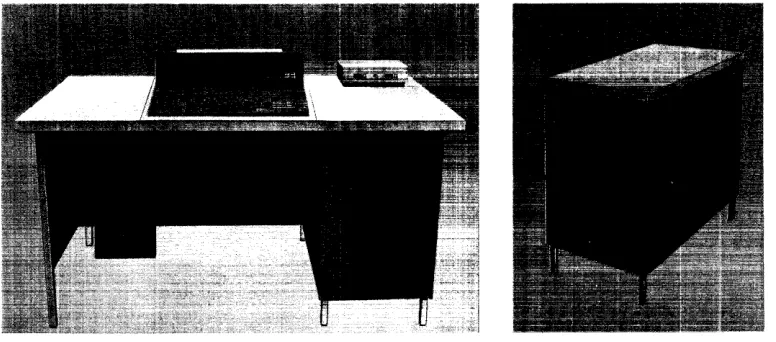
The IBM 1447 Console, Model 2, with the IBM 1447 Model 2 Inquiry Unit (Figure 5) has all the operating keys and lights of the Model 1, plus the input/output printer. It can be attached to the IBM 1240, 1440, or
1460 systems.
Console
'/0
Printer
The console I/O printer combines a keyboard of 64 characters and a pin-feed platen (special feature) with the advantages of a carriageless printer. The single printing element moves horizontally when printing, no longer subjecting :forms to horizontal carriage move-ment. This printing method results in an output rate of 14.8 characters per second.
Margins, tab stops, and ribbon shift (color) are set manually by the operator. When the printing element reaches the right-hand margin, an automatic carrier-return and line-feed operation is executed. Printing is suspended during this operation and during any tabu-lation operation. This printer can print up to 130 characters per line without the pin-feed platen, and up to 128 characters per line with the pin-feed platen feature (10 characters per inch).
The printing of either ten or twelve characters per inch must be specified by the customer. Vertical
spac-Figure 5. roM 1447 Console, Model 2
IBM 1447 Console, Model 2
ing of six or eight lines per inch must also be specified by the customer. This vertical spacing then can be manually altered with a double,·space setting, resulting in either three-instead-of-six or four-instead-of-eight lines per inch.
Printer Forms
The console I/O printer can: 1. Print on cut forms
2. Feed and stack continuous pin-feed forms 3. Feed continuous-roll single-thickness paper.
With the pin-feed special feature installed, form width (pin to pin) can be 6, 7~, 8, 9, 10, 10%, 11~, 11~ or 13% inches. The form width must be specified for each pin-feed platen.
The maximum form width is 15 inches" The maxi-mum length of a printer line is 13 inches.
When using continuous forms, the forms are placed on the forms platform. The form is then inserted in a slot between the console printer and the table, and then inserted in the console printer.
The printed forms are stacked on the portion of the console inquiry station table behind the console printer.
Keyboard
The console I/O printer keyboard (Figure 6) is not mechanically connected to the printer mechanism. Seven keys on the keyboard are function keys ini-tiating space, cancel, release, carrier return and line feed, tab, shift, and shift lock.
Some of these function keys also transmit specific characters when they are pressed. The function keys and the characters they transmit are:
Function Key Character BCD Coding
Space no character C
Carrier Return
Line Feed C B 8 4 1
Tabulate A B 8 4 1
Functional-Control Characters
Besides being able to print 64 characters, the console printer can execute various printer functions when the
[image:15.615.72.311.500.697.2]I
PROCEEDII
CHECK~
~
,----SH---IIFT
I []
QJ
8
[J
8 GJ
IT]
D
[J
D
''----_SHIFT---II
SPACEI
NOTE: Characters on left side of key are the H arrangemenT; characters on right side of key are the A arrangement.
Figure 6. Console Printer Keyboard
specific functional-control characters are sent from the system in the move mode. The characters designated as functional-control characters and the printing func-tions they initiate are:
Character BCD Coding Printer Function
blank C Space
] CB841 Carrier Return
Line Feed
AB841 Tabulate
These characters can be printed when they are trans-mitted in the load mode, but the printer function is
not executed.
Five keys on the 1447 keyboard offer a choice of two special characters each (Figure 6). The 1447 is equipped with two interchangeable print elements, one containing print-arrangement A and the other print-arrangement H. The operator can change the print element to provide the special-character printing re-quired by the program. Internal coding is not affected when the print element is changed.
Word-Mark Key
When the period ( . ) key is pressed in upper shift, a word mark (inverted circumflex) is printed. Transmis-sion of the word mark with its associated character depends upon the operation being performed.
Cancel Key
The cancel key is used to inform the system that the message should be disregarded. The key operation: 1. Sets the inquiry-clear (
* )
latch on in the system. 2. Turns on the red type light on the console.3. Inserts a C-bit in core storage.
4. Initiates a carrier-return and line-feed operation. 5. Disconnects the printer from the system.
Release Key
The release key is used to end a printer-to-system operation. When in normal shift status, the key opera-tion:
1. Inserts a group-mark with word-mark in core stor-age.
2. Initiates a carrier-return and line-feed operation. 3. Disconnects the printer from the system.
(When the release key is pressed during an alter op-eration, the group-mark with word-mark is not sent to the system.)
Shift and Shift-Lock Keys
[image:16.615.51.551.63.254.2]Figure 7. Margin Stops
Console I/O Printer Keys and Levers
Tab Contr<>1 (Clear and Set)
To clear tab settings, tab to each stop and press the
CLR (or top) of the tab control (Figure 7). To set a
tap stop, position the carriage to the desired point on the writing line and press the SET (or bottom) of the
tab control.
Margin Stop
The margin stops limit the length of the line to be typed. To set the margin stops:
1. Lift the I/O printer cover.
2. Space until the position indicator is at desired lo-cation iQf new margin.
3. Push the margin stop toward the typewriter, and align the red mark on the margin stop with the typing position indicator.
To set the left margin stop" push in the left margin stop and slide it to the desired position on the margin guide.
Figure 8. Impression and Form Controls
Multiple-Copy Control Lever
[image:17.615.75.568.68.167.2]To compensate for additional copies, move the mul-tiple-copy control lever toward the rear of the printer (Figure 8). This adjusts the platen so that the printing element will strike squarely on the form. Paper weight and number of copies will determine the setting of this control. Normally, set the multiple-copy control lever on the second marking for one original with three carbon copies, and on the third marking for one original with five carbon copies.
Line-Space Lever
This lever controls the line-space movement of the platen (Figure 8). The line-space lever can be set for either single or double space.
Paper-Release Lever
[image:17.615.72.554.545.705.2]Platen Variable
This control, operated by pressing in on the left end of the platen, allows the platen to rotate freely. The platen variable is useful after reinserting a page for correction or addition.
Ribbon and Platen Procedures
Ribbon Reversal
Open the top cover of the console printer by grasping the center of the cover and pulling up and away from the printer. To close the cover, lower it and press lightly. The cover will snap shut.
Reverse the ribbon direction by moving the ribbon-reverse lever (Figure 9) to the opposite side of the ribbon cartridge.
Ribbon Installation (Figure 9)
l. Open the cover over the print element.
2. Position the carrier near the center of the carrier rod.
3. Shift the ribbon-change lever to the right, and raise the ribbon guide.
4. Lift the ribbon cartridge vertically off the carrier ribbon posts.
5. Ease the ribbon through the slots in the ribbon guides.
6. Insert a pencil in the cartridge hole, and turn the cartridge in the direction of the arrow. Rewind any excess ribbon.
Figure 9. Console Printer Ribbon
7. Hold the new ribbon cartridge with the exposed length of ribbon toward the platen.
8. Slide the ribbon down through the slots in the ribbon guides.
9. Position the cartridge on the cartridge posts, and press down firmly.
10. Rewind any excess ribbon by turning either car-tridge post in the direction of the arrow.
11. Move the ribbon-change lever to the left to lower the ribbon guide into the typing position.
Platen Removal and Replacement (Figure 8)
l. Move the paper-release lever forward.
2. Move the paper hail forward. 3. Lift the cover.
4. Press the platen spring and lift the platen.
The feed rolls are now accessible. Clean the platen, feed rolls and bail rolls periodically to assure proper paper feeding and to prevent roll marking. There is no need to remove the metal deflector.
To replace the platen, position it with the ratchet teeth to your right. Center the end plate in the groove in the platen shaft, and press down until it clicks into place.
Console I/O Printer Operation
The console I/O printer furnishes an input to the at-tached system in three ways, and provides output from the system in two ways. The various input/output operations are:
l. Console-initiated input to system 2. Program-initiated input to system 3. Console-inquiry operation
4. Console-initiated output from system 5. Program-initiated output from system.
Console-Initiated Input to the System
The following procedure is used to set up a data-transfer from the console I/O printer into the system: 1. Stop the machine.
2. Set the manual address switches to the initial ad-dress of the area that will receive the data. 3. Turn the mode switch to ALTER.
[image:18.615.53.291.506.698.2]5. Press the start key. This places the address specified in the manual address switches in the B-address register.
6. Press the type key. This places the console and the system in read status and lights the white portion of the type key light.
7. Type data on the console I/O printer. Before each character sent is stored, that core-storage position is cleared of all bits, including the WM bit. The character can be sent with or without word marks, making the operation a type of manual load opera-tion.
8. The operator ends the operation by pressing the release key. This key operation initiates a carrier-return and line-feed operation and releases the read-status interlock (which returns the system to normal processing), but does not insert a group-mark with word-mark in core storage.
Program··lnitiated Input to the System
The stored program can set up a console-printer-to-core-storage transfer by executing a READ FROM 1447 CONSOLE instruction - M/L (%TO) (BBB) R. The
A-address specifies the console printer. The B-A-address specifies the initial core-storage position of the area where the input data will be stored. The d-character R specifies a read operation, and turns on the white type light.
The console operator types the data on the console printer, and the characters enter core storage, begin-ning at the location specified by the B-address portion of the instruction.
If the operation takes place in the move mode (M Op-code), word marks cannot be entered from the console printer into core storage. Any word marks already in the area that accepts the message will re-main there.
If the operation takes place in the load mode (L Op-code), word marks can be entered from the console printer into core storage when the word-mark key is pressed. Any word marks already in the area that ac-cepts the message will be removed.
The operator enters a word mark by pressing the shift key and the word-mark key. The upper case (word-mark position) of the period key prints an inverted circumflex. The next character printed will enter a core-storage position and have a word mark associated with it.
The release key enters a group-mark with word-mark in core storage, stops the data transfer, and causes a carrier-return and line-feed operation. The stored program continues processing.
Console Inquiry
The following procedure is used to initiate a console-inquiry operation:
l. The operator presses the type key while the pro-gram is running. This sets the inquiry request (Q) latch in the system ON.
2. The stored program branches to the inquiry sub-routine after it tests the Q-Iatch and finds it on. 3. The inquiry subroutine contains a READ FROM 1447
CONSOLE instruction - M/L (%TO) (BBB) R. The
A-address specifies the console printer. The Q-Iatch is turned off and the white type light is turned on. The B-address specifies the initial core-storage posi-tion of the area where the console-inquiry data will be stored. The d-character R specifies a read operation.
4. The operator types the data on the console printer, and the characters enter core storage, beginning at the location specified by the B-address of the in-struction. Word marks are handled as described under Program-Initiated Input to System.
5. When the complete inquiry message is correctly entered in core storage, the operator ends the oper-ation by pressing the release key. This operoper-ation inserts a group-mark with word-mark in the next core-storage position, initiates a carrier-return and line-feed operation, and advances the system to the next instruction.
Input-Operation Check Conditions
The four check conditions that can occur during an input operation are:
l. Operator keying mistake
2. Input message exceeds core··storage area capacity
3. 1447~detected parity check
4. System-detected parity check.
Operator Keying Mistake
Input Message Overflow
When the input message exceeds the core-storage area capacity:
1. The group-mark with word-mark in core storage prevents any further data transfer.
2. The inquiry-clear (
* )
indicator in the system comeson.
. 3. The red type light on the console comes on.
1447 -De·tected Parity Error
A parity error detected by the 1447:
1. Turns on the inquiry-clear (*) indicator in the system.
2. Positively resets off the A-register error latch. Any parity error detected in the 1447 will reach the. A-register and would, normally, turn on the error latch and stop the system. In this instance, the error latch is kept off and the system does not stop. 3. Turns on the red type light on the console.
System-Detected Parity Error
A parity check detected by the A-register turns on the A-register error latch 'and stops the system. The parity is corrected, and the character is stored in core storage with the correct parity.
Console-Initiated Output from the System
The following procedure is used to set up a data trans-fer from the system:
1. Stop the machine.
2. Set the manual address switches to the initial ad-dress of the core-storage area that contains the data to be sent to the console.
3. Turn the mode switch to CHARACTER DISPLAY.
4. Press the B-address register key.
5. Press the start key. This places the address specified in the manual address switches in the B-address register.
6. Press the type key. This places the console and the system in a write status, and the printing operation begins automatically.
7. Printing continues until the stop key is pressed. Pressing this key also releases the write-status inter-lock, which allows the system to return to normal processing and returns the carrier to the left-hand margin, causing a line-feed operation.
Program-Initiated Output from the System
The stored program can set up data transfer from core-storage to the console I/O printer by executing a
WRITE ON 1447 CONSOLE instruction M/L (%TO) (BBB) W. The A-address specifies the console printer and turns on the white type light. The B-address specifies the initial core-storage position of the data message that will be sent to the console printer. The d-character W specifies a write operation .
The data reads out of core storage, beginning at the address specified in the instruction and continuing until a group-mark with word-mark is encountered. The group-mark with word-mark ends the operation, but does not print. A carrier-return operation, with an associated line-feed operation, occurs, and the system advances to the next instruction.
1£
the end of a printed line is reached before the group-mark with word-mark is sensed, printing is suspended, and a carrier-return and line-feed opera-tion is executed. When the carrier reaches the left-hand margin, the printout operation continues.When a console-printer write operation is executed in the move mode, word marks are ignored. The char-acter with an associated word mark is printed as a character only. Functional-control characters cause the specified carrier movement on the console printer, but the characters do not print.
When a console-printer write operation is executed in the load mode, the word marks are printed. The word mark (inverted circumflex) is printed before the associated character is printed. Functional-control characters are also printed. The carrier movement spe-cified by the character does not occur when the write operation is executed in the load mode.
Output-Operation Check Conditions
The two check conditions that can occur during an output operation are:
1. System-detected parity check 2. 1447-detected parity check.
System-Detected Parity Error
A parity error detected by the B-register turns on the B-register error latch and stops the system at the end of the printout operation. The character in error is printed as an underscore (_).
1447-Detected Parity Error
A parity error detected by the 1447 circuitry:
2. Turns on the red type light on the console.
3. Depending on the BCD coding involved, some other character may be printed.
Conditiolll Indicators
Two indicators reflect the various system-1447 condi-tions that occur. The status of these indicators is checked by the system when it executes a BRANCH IF INDICATOR ON instruction - B (III) d with the proper
d-character. The indicator names, the d-characters that test the indicators, and the conditions that set the indicators are:
Inquiry-RE!quest (d-character Q)
The Q-indicator normally signifies that the console I/O printer has a message to send to the system. The indi-cator turns on during a console-inquiry operation when the console operator presses the type key on the con-sole.
Inquiry-Clear (d-character *)
This indicator and its associated red type light on the 1447 console turn on:
l. When the console operator makes a keying mistake and instructs the system to disregard the message (by pressing the cancel key).
2. When the input message exceeds the core-storage area capacity.
3. When the 1447 circuitry detects a parity check dur-ing the 1447-to·-core-storage transfer.
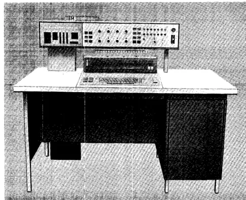
IBM 1447 Console, Model 3
The IBM 1447 Console, Model 3 (Figure 10), provides the 1401 system user with a fast means of communica-tion. All the advantages of the IBM 1407 Console
In-quiry Station, plus the increased printout speed of 14.8 characters per second, provides the console oper-ator with an efficient and time-saving method of in-quiry and reply.
Before the 1447, Model 3, can be attached to a 1401 system, the IBM 1409 Console Auxiliary (Figure 11)
and the 1409 adapter special feature must be installed. The Model 3 does not have the indicator panel or the operator panel. These panels are located on the 1401 processing unit. Several additional keys and lights, located on the printer keyboard, are used dur-ing I/O printer operations. The additional keys and lights are:
Proceed Light
The proceed light glows when the console I/O printer is selected to operate.
Check Light
The check light glows when the inquiry-clear indicator is turned on.
Reset Key
The reset key is used with the type key, on a 1447 Model 3 having buffer storage. The reset key is not required on the unbuffered model.
Figure 10. IBM 1447 Console, Model 3
Alter Type-In Key
When the CPU mode switch is set to ALTER, this key
must be pressed to allow storage entry of keyboard information. Characters enter storage starting at the address indicated by the B-storage address register.
Type Stop Key
This key is used to terminate a character-display type-out operation.
Type Key
During manual operation, the type key initiates a stor-age type-out operation, beginning with the address indicated by the CPU B-storage address register. The CPU mode switch must be in alter mode.
During programmed operation, the type key is used to perform the following functions.
Buffer: The type key initiates request to the buffer. CPU selection of the 1447 permits keyboard entry into the buffer. Press the release key to turn on the inquiry-request (Q) latch.
Buffer and Polling: The type key initiates a request to the buffer. Subsequent CPU selection of the 1447 being polled allows keyboard information to enter buffer storage.
Unbuffered: The type key turns on the inquiry-request (Q) latch. CPU selection (by a branch on Q and a read Op) allows the operator to enter information from the keyboard.
Unbuffered and Polling: This initiates the turn-on of the Q-Iatch when the 1447 is polled.
[image:22.612.53.441.539.710.2]The IBM 1447 Console, Model 4, (Figure 12) has all
the functions and capabilities of a 1447, Model 2, plus the lights, keys, and switches needed to operate an IBM
1448 Tra.nsmission Control Unit. This console can be attached to the IBM 1240, 1440, or 1460 systems.
With the 1448 attached to the system, the manual address switches and the power-on switch have addi-tional functions. A new section of display lights on the indicator panel, a 1448 start-reset key, and a 1448 check-reset key are added to complete the necessary controls.
Manual Address
The two manual address switches (units and tens) address a given data or control character in core buffer. To do this, set the units and tens switches to the line number with which the character is associated (the inner numbers refer to the 1448). The control character for a given line can be addressed by setting the line number in the units and tens switches.
Power On/Off Switch
This switch turns the main power supply for the sys-tem and the 1448 off and on. The switch is operated upward to turn power off, and downward to turn power on. After being operated, the switch automati-cally returns to a central position.
Figure 12.. IBM 1447 Console, Model 4
IBM 1447 Console, Model 4
Display Lights
These back-lighted indicators (Figure 13) provide in-formation about the location and bit configuration of data as it stands in storage.
Status. This light comes on to indicate a parity error
in status or an invalid-processor status. The other display lights in this column refer to the status of the system:
PAR (Parity)
TSM (Transmit)
REC (Receive)
ESA (End of Storage Area) CTL (Control)
CK (Check) IDL (Idle)
EOB (End of Block)
RDY (CPU is Ready)
Check. This light comes on to indicate a data parity
error. The other display lights in this area include:
LRC comes on to indicate a longitudinal redundancy
check at the end of a transmission.
OVL (Overflow) comes on to indicate that a 1448
buffer overflow occurred because the program ex-ceeded the maximum allowable noninterruptable interval, or because of a processor-stop condition.
STATUS CHECK
PAR lRC
TSM OVl
REC RNG
ESA OS
cn
SQ 1CK SQ2
IDl REQ
EOB INT
RDY
[image:23.613.72.315.506.704.2] [image:23.613.332.545.512.697.2]RNG comes on when transmission of an invalid ad-dress occurred for the message-storage area.
as (Out of Step) comes on to indicate that at the end of the scan operation, the 1448 was not at the last channel address.
sQ1 and sQ2 indicate the sequence of line-control operations
REQ (Request) indicates the request for interrupt is on.
INT (Power Interlock) comes on to indicate that
IBM 1026 Transmission Control Unit
The IBM 1026 Transmission Control Unit is an eco-nomical means of entering numeric, alphabetic, and special-character data directly into the IBM 1240, 1401, 1440, or 1460 Data Processing Systems from a half-duplex multipoint communication line. As many as four 1026 units can be attached to a data processing system. Information can be transmitted on a half-duplex line in either direction, but in only one direc-tion at a time. This IBM Tele-processing system com-ponent directs and regulates the flow of data, and provides compatibility among terminals and process-ing and exchange devices.
The 1026 transmission control unit operates with most of the controls that the IBM 1448 uses, except that it can handle only one line. The four instructions used are four of the instructions that are used with the IBM 1448 Transmission Control Unit:
ENABLE INTERRUPT
ENABLE INTERRUPT AND BRANCH DISABLE INTERRUPT
DISABLE INTERRUPT AND BRANCH
When a 1026 is installed with a 1447, the following programming examples must be considered.
power is not on, and that the dataset equipment for the addressed line is not ready to operate.
NOTE: For automatic-calling lines, the INT light will be on from the end of one call until the establishment of a connection to the remote terminal for the next call.
1448 Start-Reset Key
This key resets the complete IBM 1448 system.
1448 Check-Reset Key
This key resets the IBM 1448 error indicators.
To write to the 1447 console:
WCONSO SBR EXITW+3
V6SEL CV 6
BIN U6SEL, D
WCP TYPEW
EXITW B 0
TYPEW DA lX100, G 1,1
To read from 1447 console:
RCONSO SBR EXITR+3
WI CU 6
WCP POLST BIN Wl,*
W2 CU 6
BIN Rl,Q
B W2
Rl RCP TYPER
EXITR B 0
TYPER DA lX200, G
1,1
POLST DeW @AO@,G
Save return to main line. Select 1026 channel. Branch if bujffer busy. Write to console printer. Branch to main line. Typeout I/O storage area.
Save return address to main line.
Select 1026 channel. Poll the console. Branch if error. Select 1026 channel. Branch if service request. Branch if no service re-quest.
Read from console. Re