TM
Virtual Navigation of Complex Scenes using Clusters of Cylindrical Panoramic Images
Sing Bing Kang and Pavan K. Desikan
CRL 97/5
Cambridge Research Laboratory
The Cambridge Research Laboratory was founded in 1987 to advance the state of the art in both core computing and human-computer interaction, and to use the knowledge so gained to support the Company’s corporate objectives. We believe this is best accomplished through interconnected pur-suits in technology creation, advanced systems engineering, and business development. We are ac-tively investigating scalable computing; mobile computing; vision-based human and scene sensing; speech interaction; computer-animated synthetic persona; intelligent information appliances; and the capture, coding, storage, indexing, retrieval, decoding, and rendering of multimedia data. We recognize and embrace a technology creation model which is characterized by three major phases:
Freedom: The life blood of the Laboratory comes from the observations and imaginations of our
research staff. It is here that challenging research problems are uncovered (through discussions with customers, through interactions with others in the Corporation, through other professional interac-tions, through reading, and the like) or that new ideas are born. For any such problem or idea, this phase culminates in the nucleation of a project team around a well articulated central research question and the outlining of a research plan.
Focus: Once a team is formed, we aggressively pursue the creation of new technology based on
the plan. This may involve direct collaboration with other technical professionals inside and outside the Corporation. This phase culminates in the demonstrable creation of new technology which may take any of a number of forms - a journal article, a technical talk, a working prototype, a patent application, or some combination of these. The research team is typically augmented with other resident professionals—engineering and business development—who work as integral members of the core team to prepare preliminary plans for how best to leverage this new knowledge, either through internal transfer of technology or through other means.
Follow-through: We actively pursue taking the best technologies to the marketplace. For those
opportunities which are not immediately transferred internally and where the team has identified a significant opportunity, the business development and engineering staff will lead early-stage com-mercial development, often in conjunction with members of the research staff. While the value to the Corporation of taking these new ideas to the market is clear, it also has a significant positive im-pact on our future research work by providing the means to understand intimately the problems and opportunities in the market and to more fully exercise our ideas and concepts in real-world settings.
Throughout this process, communicating our understanding is a critical part of what we do, and participating in the larger technical community—through the publication of refereed journal articles and the presentation of our ideas at conferences–is essential. Our technical report series supports and facilitates broad and early dissemination of our work. We welcome your feedback on its effec-tiveness.
Virtual Navigation of Complex Scenes using Clusters of Cylindrical
Panoramic Images
Sing Bing Kang and Pavan K. Desikan
1September 1997
Abstract
The traditional approach of generating novel virtual views of an object or a scene is to render the appropriate 3-D model. Higher realism can be achieved by texture-mapping object surfaces or simulating surface reflectance properties. The alternative is to render directly from the original images; this approach, which is based on pixel interpolation or reprojection, is called image-based rendering.
In this technical report, we describe a technique that enables virtual navigation within a com-plex environment using an image-based rendering technique. In particular, we make use of clusters of cylindrical panoramic images. Each cluster of panoramic images allows the user to smoothly navigate within a particular area, say within a single room. Having a collection of such intercon-nected clusters would enable the user to seamlessly navigate within a complex environment, such as an entire floor of a building, with each cluster representing a room. To achieve this goal, we ex-amine a few techniques for image-based rendering using a cluster of cylindrical panoramic images to synthesize views from virtual viewpoints. We also describe our method for enabling smooth transition between clusters.
c Digital Equipment Corporation, 1997
This work may not be copied or reproduced in whole or in part for any commercial purpose. Per-mission to copy in whole or in part without payment of fee is granted for nonprofit educational and research purposes provided that all such whole or partial copies include the following: a notice that such copying is by permission of the Cambridge Research Laboratory of Digital Equipment Corpo-ration in Cambridge, Massachusetts; an acknowledgment of the authors and individual contributors to the work; and all applicable portions of the copyright notice. Copying, reproducing, or repub-lishing for any other purpose shall require a license with payment of fee to the Cambridge Research Laboratory. All rights reserved.
CRL Technical reports are available on the CRL’s web page at http://www.crl.research.digital.com.
Digital Equipment Corporation Cambridge Research Laboratory One Kendall Square, Building 700
CONTENTS i
Contents
1 Introduction 1
1.1 Previous work . . . 1
1.2 Organization of technical report . . . 3
2 General idea–Using multiple panoramic clusters 4 2.1 Extracting information for a panoramic cluster . . . 5
3 Rendering techniques within a cluster 5 3.1 Forward mapping . . . 6
3.1.1 Occlusion . . . 6
3.1.2 Speeding up forward mapping . . . 7
3.2 Inverse mapping . . . 8
3.2.1 Image smoothing . . . 8
3.2.2 Geometric interpolation . . . 9
3.3 Texturing issues . . . 10
3.4 Experimental results . . . 11
4 Moving between panoramic image clusters 13 4.1 Indicating “hotspots” . . . 15
4.2 Moving to “hotspot” and changing scenes . . . 16
5 Discussion 17
ii LIST OF TABLES
List of Figures
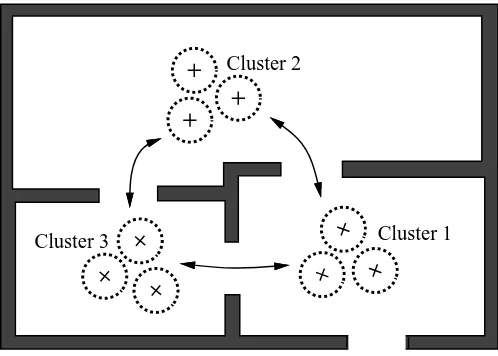
1 Virtual navigation using multiple panoramic clusters (3 clusters in this example). . 3
2 Forward mapping . . . 6
3 Handling occlusion using back-to-front ordering (top view). . . 7
4 Different cases for forward mapping (top view). . . 9
5 Geometric interpolation for filling in holes left by forward mapping. . . 10
6 Results for a close-up view: (a) Forward mapping only, with the rest with forward mapping and (b) Smoothing with fixed radius, (c) Smoothing with adaptive radius, and (d) Geometric interpolation. . . 12
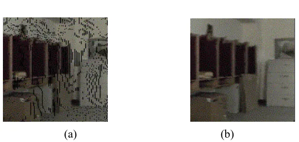
7 Results for a distant view: (a) Forward mapping only, and (b) Smoothing (with fixed radius and adaptive radius) and geometric interpolation. Only one is shown for the three reverse mapping techniques because the images are virtually indistin-guishable. . . 12
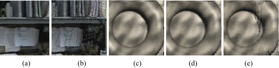
8 Using a single panoramic image source ((a), (c)), and some worst case effects of using multiple sources: two panoramic images ((b), (d)), and three panoramic images (e). . . 13
9 First cluster. . . 14
10 Second cluster. . . 14
11 Third cluster. . . 15
12 Example of “hotspots” (indicated by hollow squares) and supporting anchor points (indicated by crosses). The arrows indicate the direction of transition between panoramic clusters. . . 16
13 Sequence of snapshots taken during motion to one “hotspot” (a)-(e), transitioning from one cluster to another (f)-(i), and arrival at the destination cluster (j). . . 18
1
1
Introduction
The ability to synthesize new views from many different virtual viewpoints is important in many current and future applications, in areas that range from games and entertainment to business (e.g., real estate, tourism) and education. A typical application would involve real-time interactive walk-throughs within a virtual environment. The scene to be displayed remains the same, but the view position and direction of the virtual camera are controlled by the user.
The traditional method for producing such walkthroughs is based on 3-D model-based ren-dering, where views are generated by directly rendering 3-D models at specified viewpoints. The 3-D representation of the object or scene can either be created using a geometric modeler or from real data. Real 3-D data can be obtained using a 3-D digitizer or a rangefinder, or by applying a stereo algorithm on multiple images of the same scene or objects at different camera viewpoints. In scientific or biomedical visualization, the input data may be multidimensional.
In the specific case of visualizing 3-D objects or scenes, the resulting virtual views can be made more photorealistic by either texture-mapping images of actual objects onto the surfaces of models, or simulating surface properties using physically-based reflectance models. However, it is difficult to produce photorealistic images in a timely fashion without the use of both sophisticated and expensive rendering software and graphics hardware accelerators.
An alternative method for rendering is to create new views directly from images, called image-based rendering. Novel virtual views created using this approach can be as high a quality as the input images. As a result, it can be relatively easy to produce photorealistic images from images of real scenes. The philosophy of image-based rendering is that all the information for rendering is available in the images themselves. A survey of image-based rendering techniques is given in [7].
We are particularly interested in developing an image-based rendering system that allows a user to smoothly navigate within a large and complex environment (such as a multiple room en-vironment). While there are techniques to allow navigation within a restricted range of virtual camera motion [1, 12], none has addressed the problem of allowing virtual navigation along a long, continuous path.
1.1
Previous work
2 1 INTRODUCTION
to pan and tilt the virtual camera to view (after dewarping) a section of a cylindrical panoramic image of a real scene. Other commercial products are based on a similar principle, such as Infinite Pictures’ SmoothMove, IBM’s PanoramIX, and RealSpace, Inc.’s RealVRTM. Instead of using cylindrical panoramic images, Interactive Pictures Corp.’s IPIX (formerly Omniview’s Photobub-ble) uses spherical images instead.
On the research front, mosaics are constructed to represent a wide scene; examples include rectilinear panoramic images (e.g., [4, 17, 15]), cylindrical panoramic images (e.g., [1, 12, 8]), spherical mosaics [20, 18], super-resolution images (e.g., [5]), image mosaics with identified mul-tiple motions (e.g., [14, 19]), and image mosaics with identified parallax (e.g., [10]). However, only cylindrical and spherical mosaics allow 360 viewing in at least one direction. Out of the work listed, only [12] and [8] allow virtual navigation involving arbitrary translational motion. This is done using multiple cylindrical mosaics. Both systems are restricted to viewing of one wide scene. One approach to viewing a complex, interconnected set of wide scenes is to construct the appropriate 3-D model and render it. For real scenes, constructing such a 3-D model is difficult to achieve with high accuracy [6] without resorting to using accurate, expensive rangefinders.
The goal of our work is to enable smooth virtual navigation along a long, continuous path within a large complex environment. An example of such complex environment is a multi-room floor of a building, where one or a small number of panoramic images taken at close proximity to each other is not sufficient to visualize and represent the entire environment. There are two options to realize this goal:
Use a relatively dense sampling of panoramic snapshots of the entire environment, or
Use a select number of clusters of panoramic snapshots strategically chosen to represent the environment.
1.2 Organization of technical report 3
Cluster 1 Cluster 2
[image:9.612.182.431.109.287.2]Cluster 3
Figure 1: Virtual navigation using multiple panoramic clusters (3 clusters in this example).
tradeoff would result in the user not being able to navigate and get high quality image reconstruc-tion at all viewpoints. The idea for opreconstruc-tion (2) is shown in Figure 1.
This technical report also explores some of the techniques for image-based rendering. For modeling wide scenes that have a angular span close to or greater than 180 , flat images are mathe-matically unwieldy. Cylindrical and spherical panoramic images offer a much better mathematical generalization for modeling such a scene. The approach that we use is to reproject the pixels in a geometrically consistent manner. As in [12], we use cylindrical panoramic images as input, though the concept can be extended to spherical images as well.
1.2
Organization of technical report
4 2 GENERAL IDEA–USING MULTIPLE PANORAMIC CLUSTERS
2
General idea–Using multiple panoramic clusters
In work such as those of [12] and [8], the user has the ability to view the scene at any vantage point, even at locations not coincident with any of the projection centers corresponding to the previously recorded images. However, they are restricted to visualization of a single wide scene at a time. We add to this the ability to not only move within a wide scene, but to move from one wide scene to a different wide scene in a smooth, seamless manner. We represent each wide scene with a cluster of panoramic images, each cluster consisting of at least three panoramic images. This idea is depicted in Figure 1. Travel between clusters is through an access point called a “hotspot,” using the term for Apple’s QuickTime VRTM. The alternative is to have a dense panoramic sampling along a path. This will allow high quality view reconstruction within a larger viewing space. However, it is potentially not very practical as a large number of panoramic images will be required to represent many pockets of a large, complicated interconnected series of wide scenes. This, in turn, will result in a huge demand for both computational and memory resources.
2.1 Extracting information for a panoramic cluster 5
2.1
Extracting information for a panoramic cluster
We assume that the camera baselines within a cluster of panoramic images are small enough so that there is almost complete visual overlap between the constituent panoramic images. This allows automatic (or in the worst case, guided) registration to be performed.
As mentioned earlier, the scene to be modeled is assumed to be a static scene. For ease of modeling wide scenes, we require cylindrical panoramic images. The input is obtained by taking a sequence of images while rotating the camera about a vertical axis passing through the camera projection center. The panoramic image is a composite of these rotated camera images [12, 8]. At least two cylindrical panoramic images are needed to capture the geometry of the scene.
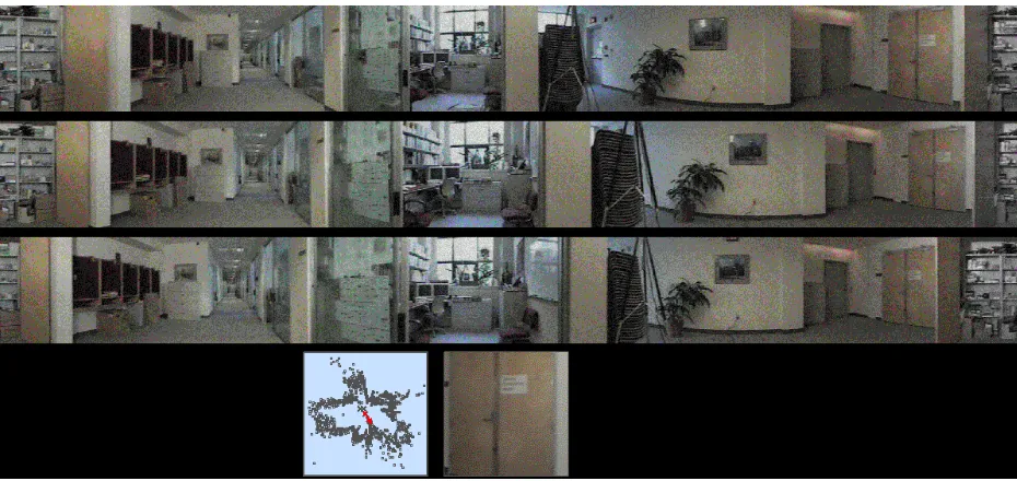
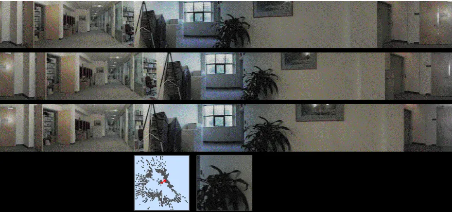
Pixel correspondence between pairs of panoramic images is obtained by using the spline-based registration technique, which attempts to deform a mesh in order minimize the intensity difference between the reference image and the warped second image [16]. Once we have the pixel corre-spondences, we use the 8-point algorithm [11] to recover the camera parameters and position up to a scale factor. In particular, we use the pixel normalization variant of the 8-point algorithm for higher stability [3]. We need to know the relative positions of the camera and the orientation of the camera for image-based rendering. The focal length of the camera is also assumed to be known. The focal length can be determined using either direct calibration using a calibration pattern or using the image sequence itself (e.g., [9]). Note that it is not necessary that the focal lengths of the cameras for the different panoramic images be identical for us to perform image-based rendering. However, we need to know the focal length of each individual camera. In our work, we assume that the focal lengths associated with all panoramic images are the same. This is a reasonable as-sumption, since all the images used in our work are taken with the same camera under a fixed focal length setting. n example of a cluster of panoramic images and its recovered structure is shown in Figure 9.
3
Rendering techniques within a cluster
6 3 RENDERING TECHNIQUES WITHIN A CLUSTER
Panoramic image 1 Panoramic image 2
[image:12.612.167.442.110.269.2]Virtual panoramic image
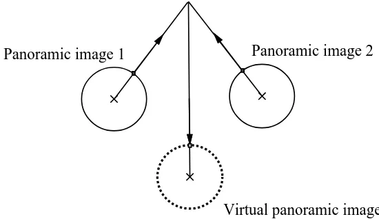
Figure 2: Forward mapping
3.1
Forward mapping
Forward mapping refers to the process of projecting pixels in texture space (available panoramic images) to the final screen space (rendered virtual view). This simple idea is depicted in Fig-ure 2. The forward mapping process is equivalent to finding the 3-D point associated with the two corresponding points in panoramic images 1 and 2, and then projecting the point onto the virtual panoramic image. The final rendered virtual view is the dewarped or “flattened” version of the frontal section of the virtual panoramic image.
One fundamental issue that has to be handled in rendering new images correctly is that of object occlusion, or depth ordering.
3.1.1 Occlusion
The forward mapping is a many-to-one mapping, and this is caused by object occlusion. As a result, occlusion has to be handled correctly in order to generate correct views from virtual view-points. A straightforward but inefficient method for handling occlusion information is to compute depth at every pixel and apply the usual z-buffering technique. However, as noted by McMillan and Bishop [12], a depth buffer is not necessary if we can find a simple back-to-front ordering. This ordering is indexed simply by the cylindrical angular coordinate in the cylindrical reference view.
3.1 Forward mapping 7
Reference View Second View
Virtual View
Epipole 1 Epipole 2
P
2 1
[image:13.612.191.423.115.323.2]P
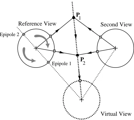
Figure 3: Handling occlusion using back-to-front ordering (top view).
from Epipole 2 to Epipole 1 in the reference panoramic image gives us a consistent back-to-front ordering.
Once we have the back-to-front ordering, we just reproject the pixels in the reference image onto the virtual cylinder, replacing the pixel with a new value. This algorithm is similar in spirit to the painter’s algorithm and performs the hidden surface removal. In the example given in Fig-ure 3, the pixel associated with the closer 3-D point, i.e.,P2, is correctly projected onto the virtual
cylindrical image.
3.1.2 Speeding up forward mapping
We approximate the limited human visual field with a 160160 square viewing window. This
viewing window is usually much smaller than the size of the cylindrical panoramic image. We can take advantage of this fact to speed up the reprojection computation. In other words, the main speedup in rendering virtual views comes from the fact that we are not computing the entire virtual cylinder, but rather only a small portion of the virtual cylinder.
8 3 RENDERING TECHNIQUES WITHIN A CLUSTER
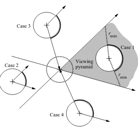
solid circles, and the virtual panoramic image shown as a dashed circle. For each of the cases, the regions appropriate for scanning are in solid thick arcs.
Case 1: The center of the reference camera lies in the view pyramid. At first glance, it would seem
that in this case, no speed up is possible as the pixels on the virtual cylinder could get their values from any of the pixels on the reference cylinder. As a result, it would appear that a complete scan is necessary to ensure the correctness of the algorithm.
However, we can assume that there are no objects closer to the projection center of the reference panoramic image thanrmin. A reasonable value ofrmin is 10 (relative to the unit
baseline length between projection centers of the reference panoramic image and a second given panoramic image). With this assumption, the range of scan can then be restricted considerably (see Figure 4).
Case 2: The center of the virtual camera lies in the view pyramid of the reference camera. In this
case, a scan is required to be performed only over the view pyramid of the reference camera.
Cases 3 and 4: The two cases are symmetric. In both these cases, the scan area on the reference
cylinder is larger than the view pyramid, but smaller than the whole cylinder.
3.2
Inverse mapping
Holes will be created by the forward mapping process if a small preimage area (on the reference panoramic image) is projected onto a larger screen area (on the virtual panoramic image), causing a loss of resolution. Holes may also occur because of the existence of regions that were not visible from any of the given cylindrical panoramic images. These regions have to be filled in order to produce a more visually appealing image. In this section, we shall discuss some techniques for filling in the holes.
3.2.1 Image smoothing
3.2 Inverse mapping 9
Case 1
Case 2 Case 3
Case 4
Viewing pyramid
[image:15.612.164.450.98.364.2]rmin rmin
Figure 4: Different cases for forward mapping (top view).
small kernel might tend to leave holes unfilled, while a large kernel might unnecessarily smooth out sharp edges.
Two image smoothing techniques involving circular interpolation kernels are implemented. The first uses a fixed radius while the other uses an adaptive radius. Both uses the weighting function
!(r)=2 ;2
r
r2 (1)
whereris the distance of the neighboring pixel to the pixel whose color is to be interpolated, and is the parameter indicating the size of the kernel. In the first technique, is set to 7 pixels.
However, in the second technique, varies; at every pixel location, is automatically set to the
distance of the central pixel to the nearest colored pixel. The second technique is very similar to the idea of elliptical weighted averaging described in [2], except that we apply a circular kernel in screen space on unfilled pixels only.
3.2.2 Geometric interpolation
10 3 RENDERING TECHNIQUES WITHIN A CLUSTER
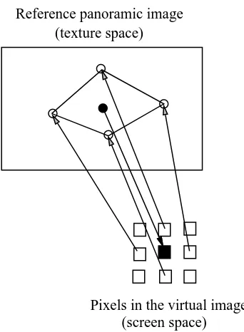
Pixels in the virtual image (screen space) Reference panoramic image
[image:16.612.220.391.109.342.2](texture space)
Figure 5: Geometric interpolation for filling in holes left by forward mapping.
the pixel in the given images. The neighbors of the hole on the scan line and in the vertical line containing the pixel are inverse mapped onto the reference image. Bilinear interpolation is then performed on the quadrilateral in the reference image to obtain an estimate of the position of the pixel in the reference image that corresponds to the hole in the virtual image. This estimate is accurate if the scene area is small or if the scene is flat in this region and far from the camera optical center. The pixel value at this position is then mapped onto the hole.
3.3
Texturing issues
When multiple panoramic images are available, we can make use of the information from the different panoramic image pairs in order to obtain the virtual view. The forward mapping is done using every pair of cylindrical panoramic images available. Any image-smoothing technique can then be used for the inverse mapping as in the case of just two cylindrical panoramic images.
3.4 Experimental results 11
cylindrical views, a simple image smoothing technique will ignore the information. Application of the geometric interpolation technique only on the reference image will result in the mapping of some incorrect pixel value to the hole. If we can identify the cylindrical panoramic image from which the portion of the scene is actually seen, then a geometric interpolation performed on this panoramic image will yield a more accurate virtual panoramic image. Thus it is possible that we accurately recover the scene from the virtual viewpoint. Since we do not know the “right” cylindrical panoramic image on which to perform geometric interpolation, we perform geometric interpolation on all the cylindrical panoramic images available to us and average over the pixel values obtained from each individual panoramic image. The averaging is actually weighted; a higher weight is accorded to pixels in the panoramic image whose camera center is closest to the virtual viewpoint. This is because we expect that the closer the virtual camera position is to a projection center of a real panoramic image, the more visually similar the virtual panoramic image is to that real panoramic image.
3.4
Experimental results
We ran our algorithms on a set of panoramic images, both synthetic and real. The size of the viewing image is160160. In general, we did not notice significant perceptual visual difference
between the image smoothing technique using the interpolation kernel with adaptive circular radius and the geometric interpolation technique for the inverse mapping, as Figure 6 shows. There are significant differences in the rendered views between the all different techniques if close-up views (such as in Figure 6) are involved. For distant views, however, the results are hardly distinguish-able, as shown in Figure 7. Overall, however, there is a reduction of quality in the reconstructed view using the image smoothing technique with fixed-radius interpolation kernel.
Some typical timing data collected are listed in Table 1. As can be seen, the rendering technique of forward mapping and geometric interpolation is the fastest amongst the three techniques using forward mapping as the first step. We have observed a significant variation in time between refresh. This can be attributed to the virtual view being a result of a varying number of projected preimage pixels, which in turn depends on the virtual camera field of view of the environment. Our program was run under the UNIX platform in DEC AlphaStation 600, which has an operating frequency of 333 MHz. Based on speed and output quality, the technique of forward mapping and geometric interpolation performed the best.
12 3 RENDERING TECHNIQUES WITHIN A CLUSTER
[image:18.612.78.536.156.287.2](a) (b) (c) (d)
Figure 6: Results for a close-up view: (a) Forward mapping only, with the rest with forward map-ping and (b) Smoothing with fixed radius, (c) Smoothing with adaptive radius, and (d) Geometric interpolation.
(a) (b)
[image:18.612.151.459.432.579.2]13
Mapping technique Average time between refresh Frequency
Forward mapping (FM) only 220 msec 4.5 Hz
FM and Fixed radius smoothing 683 msec 1.5 Hz
FM and Adaptive radius smoothing 1.15 sec 0.9 Hz
[image:19.612.106.508.108.196.2]FM and Geometric interpolation 325 msec 3.1 Hz
Table 1: Timing comparisons between the different mapping techniques for motion within the vicinity of the virtual camera viewpoint shown in Figure 6.
(a) (b) (c) (d) (e)
Figure 8: Using a single panoramic image source ((a), (c)), and some worst case effects of using multiple sources: two panoramic images ((b), (d)), and three panoramic images (e).
spline-based registration technique. It is in general very difficult to achieve exact registration.
So far we have described how new views are generated at virtual camera locations within a cluster of panoramic images. We now describe how travel between clusters is implemented.
4
Moving between panoramic image clusters
[image:19.612.82.537.262.373.2]14 4 MOVING BETWEEN PANORAMIC IMAGE CLUSTERS
Figure 9: First cluster.
[image:20.612.74.539.418.638.2]4.1 Indicating “hotspots” 15
Figure 11: Third cluster.
4.1
Indicating “hotspots”
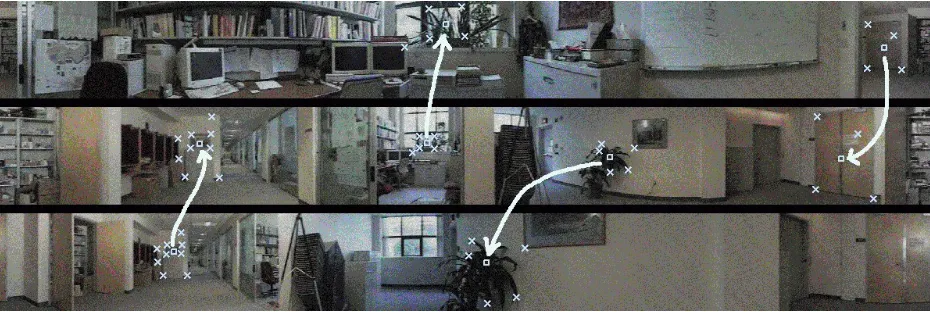
A “hotspot” can be viewed as a gateway from the current cluster to another cluster of panoramic images. From the user’s point of view, it allows the viewer to move seamlessly from one scene to another scene. In our implementation, the user or developer indicates the “hotspots” and their auxiliary points as shown in Figure 12. Each “hotspot” is represented by hollow squares while each auxiliary point is represented by a cross. “Hotspots” comes in pairs, and for each pair, there is a designated source “hotspot” and a designated destination “hotspot.” Figure 12 shows the pairs of “hotspots,” where a source “hotspot” leads to a corresponding destination “hotspot” (in the direction of the arrowed line). The auxiliary points also come in pairs; they are used to compute the global affine motion from the source to the destination portions of the reference panoramic images.
16 4 MOVING BETWEEN PANORAMIC IMAGE CLUSTERS
Figure 12: Example of “hotspots” (indicated by hollow squares) and supporting anchor points (indicated by crosses). The arrows indicate the direction of transition between panoramic clusters.
4.2
Moving to “hotspot” and changing scenes
We provide two ways of changing scenes via “hotspots.” The first is to have the user manually navigate until he or she sees a “hotspot” within view; the “hotspot” is indicated by a hollow box. The user can then indicate a change of scene by clicking inside that box. The other way is to just type a key command (current set to ’m’). This has the effect of automatically moving and reorienting the virtual camera view such that the location of the virtual camera is at the reference location and the virtual camera is pointed directly at the nearest “hotspot.” The camera motion is determined by linearly interpolating the camera position and angular orientation independently.
Once the virtual camera has been properly positioned and oriented, toward the “hotspot,” tran-sitioning between reference views of the source and destination clusters begins. The transition views are computed based on interpolated global affine motion. The global affine motion can be calculated from the corresponding the “hotspot” and auxiliary corresponding points by comput-ing the least-squares best fit through Scomput-ingular Value Decomposition (SVD). If only one pair is indicated, only the displacement in the image plane is computed. If only two pairs are selected, then only the scale and displacement in image x and y directions are computed. The global affine model is used if more than two pairs are available. Let(u
i v
i
)T and(u
0 i
v 0 i
)T be theith point in
the source image and the corresponding point in the destination image respectively. Then, using the global affine motion model,
0 B B @ u 0 i v 0 i 1 C C A =A 0 B B @ u i v i 1 C C A = 0 B B @
a11 a12 a13 a21 a22 a23
17 and 0 B B @ u i v i 1 1 C C A =A 0 0 B B @ u 0 i v 0 i 1 1 C C A =A ;1 0 B B @ u 0 i v 0 i 1 1 C C A = 0 B B @ a 0 11 a 0 12 a 0 13 a 0 21 a 0 22 a 0 23
0 0 1 1 C C A 0 B B @ u 0 i v 0 i 1 1 C C A (3)
ForN(N 3)point pairs, the elements ofAcan be extracted by solving the overdetermined
system (4) through SVD [13].
0 B B B B B B B B B B B B B B @
u1 v1 1 0 0 0 0 0 0 u1 v1 1 u2 v2 1 0 0 0 0 0 0 u2 v2 1
.. . ... ... ... ... ... u N v N
1 0 0 0 0 0 0 u
N v N 1 1 C C C C C C C C C C C C C C A 0 B B B B B B B B B B @ a11 a12 a13 a21 a22 a23 1 C C C C C C C C C C A = 0 B B B B B B B B B B B B B B @ u 0 1 v 0 1 u 0 2 v 0 2 .. . u 0 N v 0 N 1 C C C C C C C C C C C C C C A (4)
Constructing intermediate views between clusters is done through inverse mapping, i.e., using the mapping from screen space to both source and destination image spaces. The color at each pixel is the weighted average of both the appropriately sampled pixels at the source and destination images. Letbe the parameter ranging from 0 to 1 that indicates the “proximity” of the user to the
destination scene (with 0 being at the current scene and 1 being at the destination scene). Then, if
cis the color RGB vector,
c (u)=csrc(f(uA 0
))+(1;)cdest(f(uA)) (5)
where
f(uA)=(I2 2
+(A2 2
;I2 2
))u+t (6)
withI2
2 being the
22identity matrix,
A2 2
= 0 @
a11 a12 a21 a22
1 A, and
t= 0 @ a13 a23 1 A (7)
An example of automatically moving to a “hotspot,” transitioning, and arriving at a new scene is shown in Figure 13.
5
Discussion
18 5 DISCUSSION
(a) (b) (c) (d)
[image:24.612.78.537.108.250.2](e) (f) (g) (h) (i) (j)
Figure 13: Sequence of snapshots taken during motion to one “hotspot” (a)-(e), transitioning from one cluster to another (f)-(i), and arrival at the destination cluster (j).
of cluster location can enable us to visualize the complex scenes without sacrificing too much quality in the reconstructed virtual view and without prohibitively narrowing the range of virtual camera motion that results in view reconstruction with acceptable quality. However, our choice of approach opens up a range of questions.
Most of these questions relate to the quality of local navigation. Only a cluster of panoramic images of limited number (three in our case) is used to produce virtual views. As such, the quality of reconstructed virtual views is sensitive to the quality of image registration between panoramic images within the cluster. Unless both the panoramic image construction and image registration are perfect, which is impossible in practice, the quality of reconstructed views is expected to de-grade with increasing distance of the virtual camera position to the reference camera position. A reasonable solution to this is to restrict the range of motion of the virtual camera to within a certain distance from any of the panoramic image center. A distance threshold that can be used is the average baseline (i.e., average distance between cameras) within the cluster.
Each panoramic cluster is considered separately from the other clusters, with the relative cam-era positions computed separately. As a result, the relative scales across clusters may not be ex-actly consistent, unless reference distances are known a priori. Subsequently, the apparent motion within different clusters and between clusters will be different for the same mouse movement or keyboard commands. However, the effect may be inconsequential, since the human is quick to adapt and if the changes in the relative scales are small.
con-19
structed and registered exactly correctly. In such as case, one can envision taking advantage of the multiple image sources to provide super-resolution images [5]. In practice, however, we are very likely better off using just one panoramic image source.
There is also the question of how many panoramic images per cluster is sufficient for accept-able output. While two panoramic images are theoretically sufficient for view reconstruction, the quality will be poor in the vicinity of the epipole locations, or points where the line joining the two camera centers intersect the panoramic images. As a result, at least three panoramic images are required, as long as the camera centers associated with the images are not colinear. Again, there are the competing factors of high computational and memory demands against quality of reconstruction in choosing the number of panoramic images per cluster.
The placement of panoramic images within each cluster is also important. Ideally, the panoramic images should be placed as equally apart from each other as possible. The baselines should also be appropriately set as a function of the size of the scene. The guideline that we use is to have a camera baseline approximate a tenth of the scene dimension in the same direction. Hence, for a rectangularly-shaped room, the baseline parallel to the longer room dimension should be propor-tionally longer than that parallel to the shorter room dimension.
At the most technical level, there is the matter of the choice of pixel reprojection and interpo-lation techniques. We chose a combination of forward mapping and geometrically-based inverse mapping or spatial interpolation as a means of view reconstruction. This is in contrast to just apply-ing pure inverse mappapply-ing. In pure inverse mappapply-ing, two operations are necessary: the computation of the epipolar curves to search along, and the verification of intersection of the epipolar curves with the disparity curve. Ideally, the true point of origin associated with a point in screen space is the one which the epipolar curves intersect exactly with the disparity curve for all panoramic images. In practice, heuristics have to be added to find an “optimal” point. In contrast, the repro-jection computation in the mixed mapping approach is direct. However, in the case of reconstruct-ing a virtual view with a large field of view, the reprojection computation associated with forward mapping could easily overwhelm the system. In such a case, the pure inverse mapping should be used instead. However, as mentioned before, if we restrict the range of virtual camera motion, this switch in the view reconstruction approach may not be necessary.
20 REFERENCES
with each panoramic image within the cluster and the choice of the reference panoramic image per cluster are still heuristic.
6
Conclusions and future work
We have described a technique for enabling smooth virtual navigation of a complicated network of wide scenes. Any environment that involves a large expanse of space (such as an outdoor environment) or significantly large occluding partitions (such as a multi-room environment within a floor of a building) is a good candidate for this method of visualization. The technique that we have proposed uses clusters of panoramic images, with each cluster representing a separate wide scene.
Each cluster of panoramic images allows local and unconstrained navigation within a wide scene. For this purpose, we have devised a combination of forward and inverse mapping techniques to reconstruct new virtual views using the original panoramic images. The interpolation technique using the adaptive circular radius yields the best results. The geometric interpolation technique yields images of very visually similar quality, except that it is significantly faster. It is a good tradeoff between the speed of view generation and quality of reconstruction.
Predefined “hotspots” provide gateways to smoothly transition (albeit in a restricted manner) from the current cluster to the next cluster. We interpolate views using global affine motion to simulate linear camera motion from one wide scene to another.
The biggest obstacle to high quality reconstruction is the quality of image registration between panoramic images within a cluster. One way to improve the spline-based dense image registration is to incorporate some correction mechanism, such as through the imposition of hypothesized epipolar constraints at each step. Motion discontinuities may be accounted for by allowing tears and foldovers on the spline nodes.
While the current speed of performance of the implemented version is reasonable, a significant amount of engineering effort will be required to speed it further to interactive speeds. Our goal is to be able to finetune and port this visualization tool for use within the PC Windows platform.
References
REFERENCES 21
[2] N. Greene and P. Heckbert. Creating raster Omnimax images from multiple perspective views using the Elliptical Weighted Average filter. IEEE Computer Graphics and Applications, pages 21–27, June 1986.
[3] R. Hartley. In defence of the 8-point algorithm. In Fifth International Conference on Com-puter Vision (ICCV’95), pages 1064–1070, Cambridge, Massachusetts, June 1995. IEEE Computer Society Press.
[4] M. Irani, P. Anandan, and S. Hsu. Mosaic based representations of video sequences and their applications. In Fifth International Conference on Computer Vision, pages 605–611, Cambridge, Massachusetts, June 1995.
[5] M. Irani and S. Peleg. Super resolution from image sequences. In International Conference on Pattern Recognition, pages 115–120, 1990.
[6] A. Johnson and S. B. Kang. Registration and integration of textured 3-D data. In Interna-tional Conference on Recent Advances in 3-D Digital Imaging and Modeling, pages 234–241, Ottawa, Canada, May 1997.
[7] S. B. Kang. A survey of image-based rendering techniques. Technical Report CRL 97/4, Cambridge Research Lab., Digital Equipment Corp., August 1997.
[8] S. B. Kang and R. Szeliski. 3-D scene data recovery using omnidirectional multibaseline stereo. In Proc.s IEEE Computer Society Conference on Computer Vision and Pattern Recog-nition, pages 364–370, June 1996.
[9] S. B. Kang and R. Weiss. Characterization of errors in compositing panoramic images. In Conference on Computer Vision and Pattern Recognition, pages 103–109, San Juan, Puerto Rico, June 1997.
[10] R. Kumar, P. Anandan, M. Irani, J. Bergen, and K. Hanna. Representation of scenes from collections of images. In IEEE Workshop on Representations of Visual Scenes, pages 10–17, Cambridge, Massachusetts, June 1995.
[11] H. C. Longuet-Higgins. A computer algorithm for reconstructing a scene from two projec-tions. Nature, 293:133–135, 1981.
22 REFERENCES
[13] W. H. Press, B. P. Flannery, S. A. Teukolsky, and W. T. Vetterling. Numerical Recipes in C: The Art of Scientific Computing. Cambridge University Press, Cambridge, England, 1988.
[14] H. S. Sawhney and S. Ayer. Compact representations of videos through dominant and mul-tiple motion estimation. IEEE Transactions on Pattern Analysis and Machine Intelligence, 18(8):814–830, August 1996.
[15] R. Szeliski. Video mosaics for virtual environments. IEEE Computer Graphics and Applica-tions, pages 22–30, March 1996.
[16] R. Szeliski and J. Coughlan. Hierarchical spline-based image registration. In IEEE Computer Society Conference on Computer Vision and Pattern Recognition (CVPR’94), pages 194–201, Seattle, Washington, June 1994. IEEE Computer Society.
[17] R. Szeliski and S. B. Kang. Direct methods for visual scene reconstruction. In IEEE Work-shop on Representations of Visual Scenes, pages 26–33, Cambridge, Massachusetts, June 1995.
[18] R. Szeliski and H.-Y. Shum. Creating full view panoramic image mosaics and environment maps. Computer Graphics (SIGGRAPH’97), pages 251–258, August 1997.
[19] J. Y. A. Wang and E. H. Adelson. Representing moving images with layers. IEEE Transac-tions on Pattern Analysis and Machine Intelligence, 3(5):625–638, September 1994.
TM
Vir
tual
Na
vigation
of
Comple
x
Scenes
using
Cluster
s
o
f
Cylindrical
P
anoramic
Ima
g
e
s
Sing
Bing
Kang
and
P
a
v
a
n
K
.
Desikan
CRL
97/5
September