34
Genetic Algorithm based Analysis of Six-phase
Self-excited Induction Generators for
Wind Energy Conversion
S.Sasikumar
Assistant ProfessorDepartment of Electrical Engineering Annamalai University, Annamalainagar
Tamilnadu – 608002, India
S.Singaravelu
Associate ProfessorDepartment of Electrical Engineering Annamalai University, Annamalainagar
Tamilnadu – 608002, India
ABSTRACT
This paper presents the application of genetic algorithm for the analysis of six-phase self-excited induction generators (SPSEIG) by means of series compensation. A new, simple and generalized mathematical model for the steady-state analysis of SPSEIG with series compensation is proposed. The mathematical model is formed directly from the equivalent circuit of SPSEIG using nodal admittance method based on inspection. The proposed model completely avoids lengthy derivations of nonlinear equations which are followed so far. Since the model results in matrix form, inclusion or elimination of any equivalent circuit elements can be carried out easily. Moreover, this model can be used to find any combination of unknown quantities of the equivalent circuit. The matrix equation is solved by Genetic Algorithm (GA) to predict the steady-state performance of SPSEIG with three capacitor excitation configuration such as simple shunt, short shunt and long shunt. Comparative performance evaluation of SPSEIG with simple shunt, short shunt and long shunt configurations is also presented. Computed results are experimentally verified to validate the analytical approach presented in the paper.
Keywords:
Steady-state analysis, Six-phase induction generator, Series compensation, Short shunt, Long shunt, Genetic algorithm
1.
INTRODUCTION
During the last few decades, there has been a huge increase in energy demand which has accelerated the depletion of world fossil fuel supplies. Thus the development of suitable isolated power generators by utilizing the renewable sources has become great importance. Therefore, the study of self-excited induction generators has regained importance as they are particularly suitable for wind and small hydro power plants [1]. Induction generators are considered as an alternative choice to the synchronous generators because of their lower unit cost, inherent ruggedness, operational and maintenance simplicity. Three-phase self-excited induction generators are normally used in such isolated renewable energy generation. Initially, the mathematical modelling of three-phase induction generators was based on separation of real and imaginary components of complex impedance or admittance [2-4]. However, this work is tedious because of
its lengthy derivations of non linear equations. Later, the author introduced a simple mathematical model for self-excited induction generators by using graph theory concept [5] to reduce the long and cumbersome derivations.
According to reliability point of view, multi-phase induction machines (more than three-phase) are preferred [6-7] particularly, six-phase self-excited induction generators (SPSEIG) are becoming increasingly popular [8]. Although six-phase induction generators have many advantages, it suffers from inherent poor voltage regulation and its applications to power system have been apparently reduced. The voltage regulation is doubtless the bottleneck for the wide employment of six-phase self-excited induction generators. Due to the quick development of high power semiconductor devices, different types of voltage regulators can be employed. However, they are quite expensive and complex. Hence series compensation such as short shunt and long shunt configurations are proposed in this paper to improve the voltage regulation of SPSEIG.
The modelling of SPSEIG using graph theory [5] was presented in [9], in which three mathematical models for simple shunt, short shunt and long shunt were presented. But, a single generalized model can be used for all the three configurations. Moreover, for SPSEIG, even simple and generalized model can be developed instead of graph theory based modelling.
Therefore, in the present paper, the author has developed a further simplified and generalized mathematical model of six phase self-excited induction generator in matrix form using nodal admittance method based on inspection. In the proposed model, the nodal admittance matrix can be formed directly from the equivalent circuit of SPSEIG rather than deriving it using graph theory approach. The advantage of the proposed model is any equivalent circuit elements can be easily included or eliminated. Also, this model is flexible to find any combination of unknown quantities of the equivalent circuit for various capacitor and load configurations. The proposed mathematical model is also more generalized such that the same model can be utilized to determine the selection of capacitors and the steady-state performance of SPSEIG for simple shunt, short shunt and long shunt configurations (Fig. 1).
35 (GA).Since GA is a stochastic global search method, it is
[image:2.612.152.391.81.268.2]suitable for the steady-state analysis. The experimental results are found to be in good agreement with analytical results.
Fig. 1: Schematic diagram of the induction generator system employing a SPSEIG.
2.
MATHEMATICAL MODEL
The formulation of a suitable mathematical model is the first step in the analysis of a SPSEIG. The model must describe the characteristics of the individual components of the SPSEIG as well as the relations that govern the interconnections of these elements. Therefore, a mathematical model of a SPSEIG using nodal analysis based on inspection is developed from the equivalent circuit of the generator. The developed model results in a matrix form that proves convenient for computer solutions.
The steady-state equivalent circuit [9] of the SPSEIG with four nodes is shown in Fig. 2. The equivalent circuit is valid for any per unit speed ʋ.
The branch admittances of equivalent circuit are: Y1 = 1 / [Rr / (F - ʋ) +j Xr]; Y2 = 1 / [j XM];
Y3 = 1 / [j Xlm];
Y4= 1 / [Rs2 / F +j Xs2 – j Xlo2 / F2]; Y5 = 1 / [Rs1 / F + j Xs1 – j Xlo1 / F2]; Y6 = 1 / [- j Xsh2 / F2];
Y7 = 1 / [RL2 / F – j Xse2 / F 2
]; Y8 = 1 / [- j Xsh1 / F2]; Y9 = 1 / [RL1 / F – j Xse1 / F2];
The matrix equation based on nodal admittance method for the equivalent circuit can be expressed as
[Y] [V] = [IS] (1)
Where [V] is the node voltage matrix, [IS] is the source current matrix and [Y] is the nodal admittance matrix.
The [Y] matrix can be formulated directly from the equivalent circuit (Fig. 2) by inspection [10] as
Y1 + Y2+ Y3- Y3 0 0
[Y] = - Y3Y3 + Y4 + Y5- Y5- Y4
0 - Y5Y5 + Y8 + Y90
0 - Y4 0 Y4 + Y6 +Y7
3 - Phase Load
E S
S E
E
S
E S
E
S E
Six-Phase SEIG
3 - Phase Load C se1
C se2
a c b
y
x z
Prime Mover
C lo1
C lo2 Csh1 Long Shunt Short Shunt
Simple Shunt
Csh2
Long Shunt Short Shunt Simple Shunt
S
R L2 F
- j Xsh2 2 F
Rs2 j X s2 F
RL1 F
- j Xsh1 2 F
Rs1 F
j XM Rr
F-j Xlm j Xr
v Vg
F VT1
F
VT2
F VL2
F VL1
F
Is1
Is2
Ir
IM
I Ish1
IL1
IL2
j Xs1
1 2
4 3
sh2
- j Xse1 2 F
- j Xlo2 2 F - j Xlo1
2 F
- j Xse2 2 F
[image:2.612.102.504.430.592.2]36 (2)
Where
Yii = ∑ Admittance of the branches connected to ith node Yij = - ∑ Admittance of the branches connected between ith
node and jth node
Since [Y] is symmetric, Yji = Yij. If there is no branch between any two nodes, then the corresponding element in the matrix is zero.
Since, the equivalent circuit does not contain any current sources, [IS] = [0] and hence Eq. (1) is reduced as
[Y] [V] = 0 (3)
For successful voltage build up, [V] ≠ 0 and therefore from Eq. (3), [Y] should be a singular matrix i.e., det [Y] = 0. It implies that both the real and the imaginary components of det [Y] should be independently zero. Therefore to obtain required parameter which resultsdet[Y] = 0, genetic algorithm based approach is implemented.
3.
PERFORMANCE EVALUATION OF
SPSEIG
USING
GENETIC
ALGORITHM
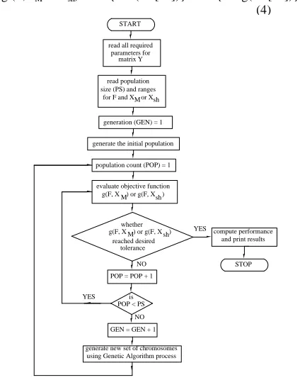
Genetic algorithm (GA) is a stochastic global search method that resembles natural biological evolution [11]. An application of GA method to obtain det[Y] = 0, which provides solution for unknown quantities, is illustrated in Fig. 3, which indicates the handling the population size and generating new set of chromosomes at the end of every iteration until convergence is reached. Thus satisfying an operating point, the objective function whose value is to be minimized is given by Eq. (4).
g (F,XM or Xsh) = abs{real(det[Y ])} + abs{imag(det[Y ])} (4)
In many optimization problems to obtain initial estimates suitably, certain trials may be required. However, in the present problem of the SPSEIG, it is easy to give the range for the unknown variables Fand XMor Xshbecause in well-designed self-excited induction generators, it is known that the slip {(F − υ)/F}is small and operation of the machine is only in the saturated region of the magnetization characteristics. So, the ranges for F can be given as 0.8 to 0.999 times the value of υand for XMas 25% to 100% of critical magnetizing reactance XMO. Similarly for Xsh, the same range 25% to 100% of CMAXcan be used, where CMAXis the maximum capacitance required under any conditions. Thus, starting from such initial estimates, the final value of Fand XMor Xshis obtained through GA. The air gap voltage Vgcan be determined from the magnetization characteristics corresponding to XM, as described in Section 4. Once the air gap voltage Vgis calculated, the equivalent circuit (Fig. 2) can be completely solved to determine the steady-state performance of SPSEIG with and without series compensation.
4.
EXPERIMENTAL
SET UP AND
MACHINEPARAMETERS
The machine used for the purpose of conducting experiments (Fig. 4) is a six-phase, 4-pole, delta connected, 2.2kW, 230V, 5A, 50Hz induction generator which consists of two identical three-phase stator winding sets namely winding set abc (set-1) and winding set xyz (set-2). The base values of the SPSEIG are
Vbase = rated phase voltage = 230V Ibase = rated phase current = 5/√3 = 2.887A Zbase = Vbase/Ibase = 79.6675 Ω
Pbase = Vbase x Ibase = 0.664 kW Nbase = 1500 rpm
fbase = 50 Hz
The parameters of the equivalent circuit of the test machine, obtained from the results of the standard tests are
Rs1= Rs2 = 6.9944 Ω, Rr = 1.0503 Ω, Xs1 = Xs2 = Xr = 3.6034 Ω, Xlm = 0.7283 Ω
Magnetization characteristics of the machine play a vital role in the analysis of SPSEIG. The magnetization curve (Fig. 5) of the SPSEIG can be determined experimentally by conducting synchronous speed test. The machine is made to run at rated synchronous speed corresponding to rated frequency, and the magnetizing reactance for different input voltages is measured. The
START
read all required parameters for matrix Y
read population size (PS) and ranges
for F and X or XshM
generation (GEN) = 1
generate the initial population
population count (POP) = 1
evaluate objective function g(F, X ) or g(F, X )M sh
whether g(F, X ) or g(F, X )M sh
reached desired tolerance
POP = POP + 1
is POP < PS
GEN = GEN + 1
generate new set of chromosomes using Genetic Algorithm process
compute performance and print results
STOP YES
NO
YES
[image:3.612.71.283.418.686.2]NO
Fig. 3: Flow chart for minimization of the objective function using genetic algorithm (GA).
Fig. 4: Photograph of six-phase self-excited induction generator (SPSEIG) with capacitor
bank.
SPSEIG Primemover
37 variation of Vg/F (in p.u) with XM (in p.u) is non-linear due
to magnetic saturation and approximated as two straight lines using piecewise linearization technique as given by Eq. (5) and (6).
Vg/F = 1.21− 0.22 XM,XM< 1.82(5) Vg/F = 2.66 − 0.97 XM,XM ≥ 1.82 (6)
5.
RESULTS AND DISCUSSION
The selection of capacitors and steady-state performance analysis of SPSEIG as given below are presented in this section using the generalized mathematical model given by Eq. (2) and GA based approach as discussed in sections 2 and 3 respectively.
Selection of capacitors
o Simple shunt configuration. o Short shunt configuration. o Long shunt configuration. Performance characteristics
o Steady-state performance analysis of simple shunt configuration.
o Steady-state performance analysis of short shunt configuration.
o Steady-state performance analysis of long shunt configuration.
Comparative analysis of simple shunt, short shunt and long shunt configurations of SPSEIG.
Experiments were conducted (Fig. 4) on uncompensated (simple shunt) and series compensated (short shunt and long shunt) SPSEIG with different capacitance and loading configurations.
5.1 Selection of capacitors
The value of simple shunt capacitance and series capacitance must be chosen to yield the desired no load voltage at the given speed and to obtain the desired voltage regulation respectively.
5.1.1 Simple shunt configuration
There is a minimum value of shunt capacitance to self-excite the SPSEIG at no load. A six-phase generator can be self-excited and operated successfully with single/double capacitor bank. But, value of shunt capacitance differs in
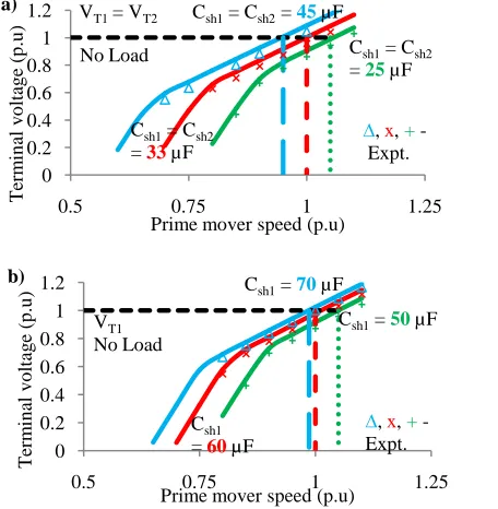
both the cases. Hence a proper value of shunt capacitance for six-phase induction generator has to be selected. The value of simple shunt capacitance to achieve the desired no load voltage for a particular speed can be predetermined by taking the shunt capacitive reactance, Xsh and frequency, F (Fig. 2) as unknown quantities.
The no load terminal voltage variation with prime mover speed for different values of equal capacitance connected to both winding sets abc and xyz is shown in Fig. 6a. It is observed that the value of simple shunt capacitance corresponding to rated terminal voltage (1.0 p.u) and rated speed (1.0 p.u) is found to be 33 µF.
Fig. 6b shows the no load terminal voltage with prime mover speed for different values of simple shunt capacitance when winding set abc alone is excited and other set xyz is kept open. From Fig. 6b, it is noticed that the value of simple shunt capacitor value is 60 µF for which the terminal voltage and speed are equal to rated value of 1.0 p.u.
5.1.2 Short shunt configuration
In order to improve the voltage regulation under loaded condition, short shunt connection is provided. For this purpose, capacitance is connected in series with the load as shown in Fig.1. This series capacitance can be used to provide excessive reactive power for the generator as load current increases. The combination of shunt and series capacitance is considered to provide excitation and self-regulation respectively. Depending on the required voltage regulation, proper value of series capacitance can be selected.
[image:4.612.81.283.109.293.2]The characteristic curve (Fig. 7) shows the change in voltage (voltage regulation) with short shunt capacitance value when both the three-phase winding sets are connected as short shunt configuration, and are subjected to resistive
Fig. 5: Variation of air gap voltage with magnetizing reactance.
0 0.2 0.4 0.6 0.8 1 1.2
0 1 2 3
Vg
/F
(p
.u
)
XM(p.u) Vg/F = 1.21 - 0.22 XM
Vg/F = 2.66 - 0.97 XM
∆ - Expt.points
Fig. 6: Open circuit characteristics when shunt capacitance connected to: (a) both winding sets abc and xyz, (b) only winding set abc.
0 0.2 0.4 0.6 0.8 1 1.2
0.5 0.75 1 1.25
T
erm
in
al
v
o
lt
ag
e
(p
.u
)
Prime mover speed (p.u) Csh1= Csh2= 45µF
No Load
∆, x, + -Expt. Csh1= Csh2
= 33µF
Csh1= Csh2 = 25µF VT1= VT2
a)
0 0.2 0.4 0.6 0.8 1 1.2
0.5 0.75 1 1.25
T
erm
in
al
v
o
lt
ag
e
(p
.u
)
Prime mover speed (p.u) Csh1= 70µF
Csh1 = 60µF
Csh1= 50µF VT1
No Load
∆, x, + -Expt.
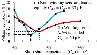
[image:4.612.314.542.149.382.2]38 load. The minimum voltage regulation of 10% is observed at
rated output power with shunt capacitance Csh1 = Csh2 = 33 µF and short shunt capacitance Cse1 = Cse2 = 100 µF, for no load voltage of 1.0 p.u at rated speed of 1.0 p.u.
The characteristic curve for short shunt configuration of single three-phase winding set abc is also shown in Fig. 7. It is observed that the minimum voltage variation is 11% with shunt capacitance Csh1 = 60 µF and short shunt capacitance Cse1 = 125 µF, for no load voltage of 1.0 p.u at rated speed.
5.1.3 Long shunt configuration
In long shunt configuration, the series capacitance is placed in series with the stator of SPSEIG (Fig. 1). As the long shunt capacitors carry stator current, they have to be rated for high current. Moreover, a short circuit across the load do not de-excite the machine, because the long shunt capacitance is still effective to supply the magnetizing reactive power.
Fig. 8 shows the voltage regulation with the value of long shunt capacitance when both the three-phase winding sets are connected as long shunt configuration, and are subjected to resistive load. From this, it is observed that the
minimum voltage regulation is 16% at rated output power with shunt capacitance Csh1 = Csh2 = 33 µF and long shunt capacitance Clo1 = Clo2 = 200 µF, for rated no load voltage and rated speed of 1.0 p.u.
The characteristic curve for long shunt configuration of single three-phase winding set abc is also shown in Fig. 8. With the value of shunt capacitance Csh1 = 60 µF and long shunt capacitance Clo1 = 225 µF, the minimum voltage regulation is found to be 15%.
5.2 Performance characteristics
The steady-state performance characteristics of SPSEIG are determined under no load condition and connection of resistive load with simple shunt, short shunt and long shunt configuration with shunt capacitance connected to (i) both the phase winding sets; (ii) any one of the three-phase winding set. The steady-state performance of all the three configurations can be computed by using the same generalized mathematical model as described by Eq. (2) with appropriate modifications in the elements of equivalent circuit (Fig. 2) along with GA based approach. The steady-state performance characteristics of SPSEIG for a particular speed can be obtained by taking XM and F as unknown quantities.
5.2.1 Steady-state performance analysis of
simple shunt configuration
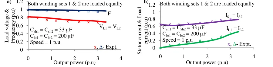
For this configuration, the equivalent circuit elements Z9, Z7, Z5 and Z4 are modified such that the terms Xse1, Xse2, Xlo1 and Xlo2 respectively are made zero in order to eliminate the effect of short shunt and long shunt capacitance. The analytical and experimental variations of load voltage, frequency, stator current and load current with output power is shown in Fig. 9. In this case, shunt capacitance (Csh1 = Csh2 = 33 µF) is connected to both the winding sets abc and xyz and both winding sets are subjected to equal resistive loading.
It can be noted from Fig. 9a that the load voltage and frequency decreases as the load on both the winding sets increases. In this mode of operation, it is observed that the voltage regulation is 23% and decrease in frequency is about 2.4% from no load to full load. From Fig. 9b, it is found that the stator current is below its rated value. The maximum power developed in this case is 3.2 p.u.
Results depicting the variation of load voltage, frequency, stator current and load current with output power are given in Fig. 10 when shunt capacitance (Csh1 = 60 µF) is connected to winding set abc only and is subjected to resistive loading. Winding set xyz is kept open. From Fig. 10a, it can be stated that the voltage regulation is 20% and drop in frequency is 1.3% from no load to full load. Also from Fig. 10b, it can be observed that the stator current is below the rated value. The maximum power developed is 1.5 p.u.
5.2.2 Steady-state performance analysis of short
shunt configuration
For short shunt configuration, the equivalent circuit components Xlo1 and Xlo2 in the elements Z5 and Z4 respectively are made zero in order to eliminate the effect of long shunt capacitance. Experimental and computed results for variation of load voltage, frequency, stator current and
Fig. 7: Maximum voltage variation with short shunt capacitance when: (a) both the winding sets abc and xyz
are connected as short shunt configuration and subjected to load. (b) single winding set abc is connected as short shunt configuration and subjected to load with winding set xyz is kept open.
8 10 12 14 16 18 20
50 150 250
V
o
lt
ag
e
re
g
u
la
ti
o
n
(
%
)
Short shunt capacitance (Cse) in µF (a) Both winding sets are loaded equally Csh1= Csh2= 33 µF
(b) Winding set -1 (abc) is loaded Csh1= 60 µF
Fig. 8: Maximum voltage variation with long shunt capacitance when: (a) both the winding sets abc and xyz
are connected as long shunt configuration and subjected to load. (b) single winding set abc is connected as long shunt configuration and subjected to load with winding set xyz is kept open.
12 14 16 18 20 22 24
50 150 250 350 450
V
o
lt
ag
e
re
g
u
la
ti
o
n
(
%
)
Long shunt capacitance (Clo) in µF (a) Both winding sets
are loaded equally Csh1= Csh2= 33 µF
[image:5.612.76.273.120.233.2] [image:5.612.78.288.470.578.2]39
Fig. 9: Variation of: (a) load voltage and frequency, and (b) stator current and load current of SPSEIG with output power when both the winding sets abc and xyz are connected as simple shunt configuration ( Csh1 = Csh2 = 33 µF ), and
are subjected to independent equal loading.
Fig. 10: Variation of: (a) load voltage and frequency, and (b) stator current and load current of SPSEIG with output power when winding set abc is connected as simple shunt configuration ( Csh1 = 60 µF ), and subjected to load with
[image:6.612.75.533.85.195.2]winding set xyz is kept open.
Fig. 11: Variation of: (a) load voltage and frequency, and (b) stator current and load current of SPSEIG with output power when both the winding sets abc and xyz are connected as short shunt configuration (Csh1 = Csh2 = 33 µF and Cse1 =
Cse2 = 100 µF), and are subjected to independent equal loading.
Fig. 12: Variation of: (a) load voltage and frequency, and (b) stator current and load current of SPSEIG with output power when winding set abc is connected as short shunt configuration (Csh1 = 60 µF and Cse1 = 125 µF), and subjected
to load with winding set xyz is kept open.
0 0.2 0.4 0.6 0.8 1 1.2
0 1 2 3 4
L o ad v o lt ag e & F re q u en cy (p .u )
Output power (p.u)
x, ∆ - Expt. Csh1= Csh2= 33 µF
Speed = 1 p.u
F
VL1= VL2
Both winding sets 1 & 2 are loaded equally
a) 0 0.2 0.4 0.6 0.8 1 1.2
0 1 2 3 4
S tato r cu rre n t & L o ad cu rre n t (p .u )
Output power (p.u)
x, ∆- Expt. Csh1= Csh2= 33 µF
Speed = 1 p.u
IS1= IS2
IL1= IL2 Both winding sets 1 & 2 are loaded equally b) 0 0.2 0.4 0.6 0.8 1 1.2
0 0.5 1 1.5 2
L o ad v o lt ag e & F re q u en cy (p .u )
Output power (p.u) Csh1= 60 µF
Speed = 1 p.u x, ∆ - Expt. F
VL1 Winding set -1 (abc) is loaded
a) 0 0.4 0.8 1.2 1.6 2
0 0.5 1 1.5 2
S tato r cu rre n t & L o ad cu rre n t (p .u )
Output power (p.u) Csh1= 60 µF
Speed = 1 p.u
x, ∆- Expt. IS1
IL1 Winding set -1 (abc) is loaded
b) 0 0.2 0.4 0.6 0.8 1 1.2
0 1 2 3 4
L o ad v o lt ag e & F re q u en cy (p .u )
Output power (p.u)
x, ∆- Expt. VL1= VL2
F
Csh1= Csh2= 33 µF Cse1= Cse2= 100 µF Speed = 1 p.u
Both winding sets 1 & 2 are loaded equally
a) 0 0.2 0.4 0.6 0.8 1 1.2
0 1 2 3 4
S tato r cu rre n t & L o ad cu rre n t (p .u )
Output power (p.u)
x, ∆- Expt. IS1= IS2
IL1= IL2 Csh1= Csh2= 33 µF
Cse1= Cse2= 100 µF Speed = 1 p.u
Both winding sets 1 & 2 are loaded equally
b) 0 0.2 0.4 0.6 0.8 1 1.2
0 0.5 1 1.5 2
L o ad v o lt ag e & F re q u en cy (p .u )
Output power (p.u) Csh1= 60 µF
Cse1= 125 µF
Speed = 1p.u x, ∆- Expt.
VL1 F Winding set -1 (abc) is loaded
a) 0 0.4 0.8 1.2 1.6 2
0 0.5 1 1.5 2
S tato r cu rre n t & L o ad cu rre n t (p .u )
Output power (p.u) Csh1= 60 µF
Cse1= 125 µF Speed = 1p.u
x, ∆- Expt. IS1
IL1 Winding set -1 (abc) is loaded
[image:6.612.78.537.245.354.2] [image:6.612.80.533.394.507.2] [image:6.612.75.539.555.670.2]40 load current with output power when both the winding sets
abc and xyz are connected as short shunt (Csh1 = Csh2 = 33 µF and Cse1 = Cse2 = 100 µF) and subjected to equal resistive loading are shown in Fig. 11.
The effect of series capacitance (in short shunt mode) on load voltage and frequency is shown in Fig. 11a. It is observed that the voltage regulation is found to be 10% from no load to full load. This indicates that the voltage profile is improved when compared to the simple shunt configuration in which the voltage regulation is 23%. Also the drop in frequency is observed as 1.9% which is low when compared to simple shunt configuration. Fig. 11b shows the variation of stator current and load current with output power and it is observed that the stator current is within its rated value. The maximum power developed is 3.5 p.u.
Fig. 12 depicts the computed and experimental variation of load voltage, frequency, stator current and load current with output power when single three-phase winding set abc is connected as short shunt configuration (Csh1 = 60 µF and Cse1 = 125 µF) and is subjected to resistive load with winding set xyz is kept open.
From Fig. 12a, it is found that the voltage regulation is 11% from no load to full load. Also it is observed that, the voltage profile is improved when compared to 20% in simple shunt configuration. It is also noticed that the reduction in frequency is 1.1% which is low when compared to simple shunt configuration. The variation of stator current and load current with output power is shown in Fig. 12b and it is observed that the stator current is below its rated value. The maximum power developed is 1.8 p.u.
5.2.3 Steady-state performance analysis of long
shunt configuration
To compute the performance of SPSEIG under long shunt configuration, the equivalent circuit components Xse1 and Xse2 in the elements Z9 and Z7 respectively are made zero. Experimental and computed results for variation of load voltage, frequency, stator current and load current with output power when both the winding sets abc and xyz are connected as long shunt (Csh1 = Csh2 = 33 µF and Clo1 = Clo2 = 200 µF) and subjected to equal resistive loading are shown in Fig. 13.
Fig. 13a shows that load voltage and frequency decrease as the load increases. It is observed that the full load voltage regulation is found to be 16% which indicates that the voltage profile is improved when compared to the simple shunt configuration but it is not good enough when compared to short shunt configuration. It is also noticed that the reduction in frequency is about 2%. From Fig. 13b, it is found that the stator current is below its rated value. The maximum power developed in this case is 3.3 p.u.
[image:7.612.85.535.402.513.2] [image:7.612.88.534.563.676.2]Fig. 14 shows the analytical and experimental variation of load voltage, frequency, stator current and load current with output power when single three-phase winding set abc is connected as long shunt configuration (Csh1 = 60 µF and Clo1 = 225 µF) and is subjected to resistive load with winding set xyz is kept open. From Fig. 14a, it is found that the voltage regulation is 15% from no load to full load. Also it can be noticed that the drop in frequency is 1.2%. From Fig. 14b and it is observed that the stator current is below its rated value. The maximum power developed is 1.7 p.u.
Fig. 13: Variation of: (a) load voltage and frequency, and (b) stator current and load current of SPSEIG with output power when both the winding sets abc and xyz are connected as long shunt configuration (Csh1 = Csh2 = 33 µF and Clo1 =
Clo2 = 200 µF), and are subjected to independent equal loading.
Fig. 14: Variation of: (a) load voltage and frequency, and (b) stator current and load current of SPSEIG with output power when winding set abc is connected as long shunt configuration (Csh1 = 60 µF and Clo1 = 225 µF), and subjected
to load with winding set xyz is kept open.
0 0.2 0.4 0.6 0.8 1 1.2
0 1 2 3 4
L
o
ad
v
o
lt
ag
e
&
F
requenc
y
(p.
u)
Output power (p.u) Csh1= Csh2= 33 µF
Clo1= Clo2= 200 µF Speed = 1 p.u
VL1= VL2 F
x, ∆- Expt. Both winding sets 1 & 2 are loaded equally
a)
0 0.2 0.4 0.6 0.8 1 1.2
0 1 2 3 4
St
at
o
r
cur
re
nt
&
L
o
ad
cur
rent
(
p.
u)
Output power (p.u) IL1= IL2 IS1= IS2
x, ∆- Expt. Csh1= Csh2= 33 µF
Clo1= Clo2= 200 µF Speed = 1 p.u
Both winding sets 1 & 2 are loaded equally
b)
0 0.2 0.4 0.6 0.8 1 1.2
0 0.5 1 1.5 2
L
o
ad
v
o
lt
ag
e
&
Fr
eque
nc
y
(p.
u)
Output power (p.u) Csh1= 60 µF
Clo1= 225 µF Speed = 1p.u
VL1 F
x, ∆- Expt. Winding set -1 (abc) is loaded
a)
0 0.4 0.8 1.2 1.6 2
0 0.5 1 1.5 2
St
at
o
r
cur
re
nt
&
L
o
ad
cur
re
nt
(
p.
u)
Output power (p.u)
IS1
x, ∆- Expt. Csh1= 60 µF
Clo1= 225 µF Speed = 1p.u
IL1 Winding set -1 (abc) is loaded
41
5.3 Comparative analysis of simple shunt,
short shunt and long shunt configurations
of SPSEIG
Fig. 15 shows the comparative performance analysis of SPSEIG with simple shunt, short shunt and long
shunt configurations when both winding sets and single winding set is excited with shunt capacitance respectively. It can be observed that the long shunt configuration can maintain lower load voltages while the short shunt configuration has better voltage regulation under higher load voltages.
6.
CONCLUSION
In this paper, a generalized mathematical model for steady-state analysis of SPSEIG with simple shunt, short shunt and long shunt configuration is presented. The model developed using nodal admittance method based on inspection is in matrix form, which is convenient for computer simulation. The proposed model is quite simple as it can be formulated from the equivalent circuit directly by inspection. Also, the model is equally applicable for all the three configurations of SPSEIG under both the conditions when shunt capacitance is connected across (i) both the three-phase winding sets, (ii) single three-phase winding set. The analysis shows that single three-phase capacitor bank is able to self-excite SPSEIG. This shows that, even if one of the three-phase windings lost its excitation the operation can be continued. Since SPSEIG is able to deliver two independent loads, it is possible to supply one load in the case of one winding fails thus avoids complete shutdown. A comparative performance study is also presented for simple shunt, short shunt and long shunt configurations of SPSEIG. Based on the analysis, it is observed that the short shunt configuration gives better voltage regulation when compared to simple shunt and long shunt configurations. The experimental and computed results are in close agreement which verifies the accuracy of the proposed model and solution technique.
7.
ACKNOWLEDGEMENTS
The authors gratefully acknowledge the support and facilities provided by the authorities of the Annamalai University, Annamalainagar, Tamilnadu, India to carry out this research work.
8.
REFERENCES
[1] Farret, F.A., Palle, B., and Simoes, M.G. 2005.Full expandable model of parallel self-excited induction generators. IEE Proc.-Electric Power Applications,152: pp. 96-102.
[2] Tarek Ahmed, and Mutsuo Nakaoka.2004. Static VAr compensator based terminal voltage control for
stand-alone ac and dc outputted self-excited induction generator. IEE Proc. : pp.40-45.
[3] Chan, T.F, and Lai, L.L. 2004. A novel excitation scheme for a stand-alone three-phase induction generator supplying single phase loads. IEEE Trans. on Energy Conversion,19: pp.136-42.
[4] Mosaad,M.I.2011. Control of self excited induction generator using ANN based SVC. International Journal of Computer Applications, 23: pp.22-25.
[5] Singaravelu, S., and Velusami, S. 2005. Generalized steady-state modeling and analysis three-phase induction generators. International Journal of Emerging Electric Power Systems,3: pp.1-31.
[6] Levi, E., Bojoi, R., Profumo, F., and Williamson, S. 2007. Multiphase induction motor drives – A technology status review. IET Electric Power Applications,1(4): pp.489-516.
[7] Lipo, T.A. 1980. A d-q model for six phase induction machines, Proceedings of the International Conference on Electrical Machines (ICEM), Athens Greece.pp.860-867.
[8] Wang, D., Ma, W., Xiao, F., Zhang, B., Liu, D., and Hu, A. 2005. A novel stand-alone dual stator winding induction generator with static excitation regulation. IEEE Trans. on Energy Conversion, 20: pp.826-835. [9] Singh, G.K., Senthil Kumar, A., and Saini, R.P.
2011.Performance analysis of a simple shunt and series compensated six-phase self-excited induction generator for stand-alone renewable energygeneration. EnergyConversion and Management,52: pp. 1688-1699. [10] Alexander von Weiss, 1964. Matrix Analysis for
Electrical Engineers.Princeton, New Jercy: D. Van Nostrand Company, INC.
[image:8.612.83.515.146.254.2][11] Goldberg, D.E. 2001. Genetic algorithm in search, optimisation, and machine learning. New Delhi: Pearson Education.
Fig. 15: Variation ofload voltageof SPSEIG with output power under simple shunt, short shunt and long shunt configurations when:(a) both the winding sets abc and xyz are loaded equally, and (b) single three-
phase winding set abc is loaded.
0 0.2 0.4 0.6 0.8 1 1.2
0 1 2 3 4
L
o
ad
v
o
lt
ag
e
(p.
u)
Output power (p.u)
Short shunt
Simple shunt
Csh1= Csh2= 33 µF
Cse1= Cse2= 100 µF
Clo1= Clo2= 200 µF
Speed = 1 p.u
Long shunt Both winding sets 1 & 2 are loaded equally
x, +, ∆ - Expt.
a)
0 0.2 0.4 0.6 0.8 1 1.2
0 0.5 1 1.5 2
L
o
ad
v
o
lt
ag
e
(p.
u)
Output power (p.u) Csh1= 60 µF
Cse1= 125 µF
Clo1= 225 µF
Speed = 1 p.u
Short shunt
Simple shunt
Long shunt
Winding set -1 (abc) is loaded
x, +, ∆ - Expt.