Multipath Global Rerouting for Fault Tolerant Overlay
Network (FTON) in Labeled Optical Burst-Switching
Marimuthu.G
, Dept. of IT, Krishnasamy College of Engineering & Technology,Cuddalore, India
Pragash.K,
Dept. of CSE, CK College of Engineering & Technology,
Cuddalore, India
Kaliaperumal. G
Tata Consultancy Services, India
ABSTRACT
In this paper, mainly concentrate on reduce the burst loss and Non-availability of wavelength in network; proposed an overlay model known as Fault Tolerant Overlay Network (FTON) which improves the performance of a regular IP electronic network. An FTON is created over the existing network; an FTON node collects the information about the underlying network periodically. Whenever a fault occurs in the underlying network, and in case of non availability of required wavelength, FTON nodes generate an alternate path to route the bursts. This proposed work extends the resilience concept to the Optical Burst Switched Network.
Keywords
Burst dropped; Fault Tolerant; IP-over-WDM; OBS; QoS; Resilience.
1.
INTRODUCTION
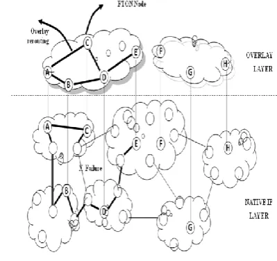
Overlay networks have recently gained attention as a viable alternative to overcome functionality limitations (e.g., lack of QoS, multicast routing) of the Internet. They offer enhanced functionality to end-users by forming an independent and customizable virtual network over the native network.
The basic idea of overlay networks is to form a virtual network on top of the native network so that these specialized overlay nodes can be customized to incorporate complex functionality without modifying the underlying native routers, overlay networks can be of different classes based on their specific purpose. Some common forms such service includes [1] are peer-to-peer (P2P) overlays, content delivery networks (CDN), and service (infrastructure) overlays.
In this work is particularly focused on the performance and stability observed in service overlays, which are overlays formed to over a value added network service to actual end-systems. The member nodes of this overlay are persistent and route traffic between one another.
1.1 Motivation
The motivation for having a FTON arises from the desire to improve on the poor performance of the underlying Internet routing protocols [1], such as the Border Gateway Protocol (BGP). BGP can take upwards of tens of minutes for a consistent view of the network topology to be established after routing failures occur. This could lead to delays in packets being delivered, and a higher frequency of packet loss.
It is also possible that when a routing failure occurs, BGP won't be able to reestablish a new route for the packet to travel. FTONs, on the other hand, take tens of seconds to repair network paths, and in certain cases they can also find routes for packets to travel even when the underlying BGP protocol cannot do.
1.2 Fault tolerant overlay network
In order to provide a better quality of service and fault detection and recovery in Optical Burst Switching Network, in this paper introduced a concept of Fault Tolerant Overlay Network over OBS Network. It is an architecture that allows Distributed Internet Application to observe and enhance the Quality of Service.
In this work, one of assumptions is that, the nodes don’t contain a wavelength converter. So to route packets across the network, same wavelength must be available at all the links throughout the route. By wavelength availability, the required wavelength must be free. If the required wavelength is not available at any link, the packet will be dropped else it will be transmitted to the next node. So this brings out a constraint known as wavelength continuity constraint.
A node in the network that provides the services or takes the transmission decision for the incoming data burst may not be able to view and predict the traffic at the other nodes as well as the condition of every link in the network.
In FTON, consider Control Overhead. However in an OBS Network, control traffic is routed through separate channel as it has to be converted from optical form to electronic form at every node. The capacity of control channel is in terms of Gigabits/sec, so it can tolerate the control overhead.
2.
ARCHITECTURE OF FTON
The Architecture of proposed FTON is show in figure 1 based on the application level routing. With the help of multilayer interaction fault detection and recovery are taken place very effectively with in second that will give more reliable and secure connection more over fault detection and recovery are taken place very effectively
FTON is an application layer overlay on top of the existing routing substrate. FTON nodes are specialized nodes which run a protocol at the application layer.
2.1 FTON
Node
will enable forwarding of packets. These information can be used by the nearby general nodes for routing of burst (to the next node) whenever necessary.
2.2 Observer
Observer is a component of FTON which gather information and summarizes them. Some of the information collected by the observer are, condition of bursts, availability of wavelength on each link, the traffic progressing towards each node, etc. From this information, the observer may come to the following conclusions: (1) certain links are overloaded i.e. wavelength is available or not. (2) Same wavelength is available between all nodes or not. (3) Any alternate path is available or not.
2.1.1
Steps involved in routing burst
Steps performed in routing the data burst across the network over the available wavelength at each link with the help of information obtained from FTON nodes are as follows:
At the General Node:
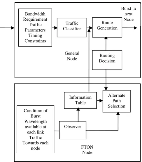
In Figure 3 illustrate the general node, the burst to be transmitted arrives at the source node, the node sends a request to the FTON seeking information about the availability of free bandwidth or channel for path selection.
The General node (GNode) extracts following information from the burst such as bandwidth requirement, traffic parameters, and timing constraints. Then, itpassed to traffic classifier which offers various services for traffic classes.
The data is further classified in the classifier to any of the available traffic classes, based on the information obtained the data traffic is forwarded to next node until it reach the destination.
At the FTON node
In FTON node observer act as a main component, that collects information from the surrounding node and links, with the collected information, FTON forms and updates the information table, Figure 3 illustrated the interaction between General Node and FTON Node.
If general node made request to FTON node, it seeks the information to the nearby FTON, then FTON node communicates with other FTON in the network and updates its information table, based on the information table obtained by FTON node has to select forwarder table to select path and transmit the burst.
The nodes will provide services to the requests made by client, such as, (1) FTON first of all checks if it can fulfill the clients request for requested services. (2) This may include estimation of available bandwidth, alternate path to transfer data, guarantee for service, network traffic analysis, etc. (3) FTON observes whether the same quality is maintained or not.
The FTON nodes are used mainly to reduce the wastage of bandwidth by checking for the available free wavelength and avoid contention in the network through prior monitoring and probing. This is done by considering the bandwidth requirements, distance between the current position of the burst and the link where contention might occur, time to transmit burst across the network, and of course the priority of the burst. Based on these values the burst will be allowed to take up the requested route else not.
There are various metrics to evaluate the proposed method; they are delay in end-to-end transmission, blocking probability, number of requests dropped, and number of applications meeting their traffic requirements. The results will be obtained under various conditions either with or without FTON nodes
.
Arriving Data
Burst Routed tonext Node Burst
Generat ion
Traffic Classificati
on
Routing Decision by FTON Nodes
Route Generat
[image:2.595.318.557.73.234.2]ion
Fig 2: General Node
[image:2.595.73.273.135.323.2]3.
WORKING MODEL FOR FTON
In this work, proposed an algorithm to group a number of General Nodes (GNodes) under each FTON Node. The FTON node will monitor the group of GNodes under it. A master node (MNode) is a node which has maximum number of links in group of GNodes belonging to the FTON Node this MNode is directly connected to the FTON Node and serves as an intermediate node between FTON Node and respective group of GNodes i.e. MNode communicates all the information from FTON Node to respective GNode and vice versa. The MNode selection procedure is as follow:
FTON Node finds number of GNodes in the network considered.
Arrange all the nodes in descending order of number of links connected to each node using swapping method.
Each FTON Node selects a MNode for itself from the array of GNodes, which is arranged in descending order. The number of MNode must be equal to number of FTON Nodes in the Overlay Network.
Now each FTON node has a MNode. All the GNodes which are linked to each MNode will be grouped under respective FTON node.
3.1 An Example
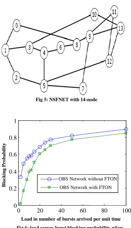
An example has been taken based on the reference [6]. In the given scenario, considered an NSFNET with 14 nodes. There is no wavelength converter, so wavelength continuity constraint exists in the network. A load of about 10 GB is to be transmitted across this network. The traffic arrives at different source and is to be carried to different destination i.e. each data burst belongs to a different source-destination pair. The data burst must be transmitted over the network with a minimum burst loss and maintaining the QoS guarantee promised by the service provider to each class of traffic.
Scenario I: In the given situation at time t=0, 2 data burst arrives at node 2 and 3 each and both of them use the same wavelength. The detail of each burst is given in table 1.
Table 1. Burst arriving at each node
Burs t No.
Sourc e
Destinatio n
Arriva l Time
Burs t Size
End Tim
e
5 3 12 0 1182 4
[image:3.595.55.299.81.359.2]7 2 11 0 692 4
Table 2. Shortest path for source-destination pair
Source Node
Destination Node
Edge Cost
Intermediate Node
2 11 2 13
3 12 3 4,13
The source node will look at the shortest path table and obtain the shortest path to the corresponding destination. The shortest path obtained is shown in table 2.
Now each source will check for the availability of the same wavelength in the network and finds that the wavelength is available. This situation will lead to contention because at a time node 13 can carry only one burst, both the burst try to use the same link. At this situation in an OBS network, one burst will be dropped.
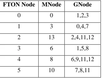
Now, analyzing the same scenario with FTON nodes, make use of a heuristic to find the number of FTON nodes and use the proposed MNode selection algorithm to select group of GNodes. A FTON Node architecture depicted in Figure 4 is used to solve the problem. Each FTON node interacts with other FTON nodes as well as with the MNodes and gather information. With this information it forms the information table and then distributes it among the other FTON nodes, respective MNode and the group of nodes under it. The FTON node contains information as shown in table III.
Traffic Classifier
Routing Decision
Alternate Path Selection Condition of
Burst Wavelength
available at each link
Traffic Towards each
node
Observer General
Node
FTON Node Information
Table
Burst to next Node Bandwidth
Requirement Traffic Parameters
Timing Constraints
Route Generation
Table 3. Information contained in FTON node
FTON Node MNode GNode
0 0 1,2,3
1 3 0,4,7
2 13 2,4,11,12
3 6 1,5,8
4 8 6,9,11,12
5 10 7,8,11
Using the FTON architecture, the FTON node 2 will find that there may be a possibility of contention at the link connecting node 4 and 13, so it will analyze the two burst and allows only one burst to take the link connecting node 4 and 13 and send the other burst through another route. FTON Nodes helps to route the traffic and reduce the burst loss.
4.
IMPLEMENTATION
The two important aspects of the proposed work is the implementation or simulation of the Time stamped Optical Burst Switching and the Mirror Rotation Table in the intermediate node that is used to route the bursts in proper direction.
4.1 Constraints & Assumptions
There are certain assumptions and constraints that are to be taken into account in this system. The various assumptions and constraints are:
All the nodes in the network have splitting capabilities.
The network is at least 2-connected so that failure of a link doesn’t disconnect the network,
All the links in the network are bidirectional
For simulation purpose considered a table (Mirror Rotation Table) which is used to rotation the burst with proper destination.
The Resilient nodes are selected based on the prioritization of the number of outgoing edges.
An optimal ratio between the Physical node and the Resilient nodes should be maintained4.2 Procedure for simulating FTON
1) Select a set of nodes as representative nodes which will be communicating directly with the Fault Tolerant Overlay Network nodes (FTON nodes).
2) Divide all other nodes in to groups in such a way that each FTON node gets complete information about its group nodes.
3) At regular intervals
a) FTON sends request message to all the nodes in its group.
b) Every node in the group responds to the request by sending information regarding link failure, wavelength cross connect failure, transmitter failure etc.
c) FTON keeps track of this information and it is shared with other FTONs by communicating with them at regular intervals.
4) Every node whenever it gets some data to transmit gets the route from IP.
5) The source node consults the FTON to find the reliability of wavelength lines in the route.
6) If all the lines are in good condition (available), then the control packet is sends and Optical Burst Switching occurs.
7) If the source node finds that the route given by the IP is not good (wavelength not available) then, the source can select an appropriate route from a set of alternative paths computed by K-Shortest Path algorithm.
8) It then checks the validity of the path using the reliability information obtained from the FTON node.
0
1
2 0
3 0
4 5
[image:4.595.85.253.456.584.2]NSFNETwith14
nodes
Overlay Network with FTON nodesFig 4: FTON architecture for the given scenario
FT
ON
N
o
d
e
MNode
Grouped under FTON Node0 Node 0
5.
RESULT DISCUSSION
Figures 6 and 7 shows the plots of Load versus Burst Blocking Probability by having the number of wavelengths WL available at each link as 3 and 5 respectively and the number of transmitters Tx and number of receivers Rx at edge nodes as 5. From the graphs, infer that OBS network with FTON has low burst loss compared to the OBS network without FTON at similar experimental conditions.
Fig. 8 plots the number of wavelengths on each link versus Burst Blocking probability for both FTON and without FTON schemes while keeping the load (burst arrival rate) constant. Burst arrival rate (parameter of the Poisson process) is taken as 5.
Here, the number of transmitters and receivers are taken as 3. From the graphs, it is evident that with FTON technique outperforms the without FTON in terms of data loss.
6.
CONCLUSIONS
Fault Tolerant Overlay Network (FTON) algorithm is to overcome both link and non-availability of wavelength in the network with the help of FTON which reliable and provide availability, Recovery can take place within a second where as the BGP-based Internet routing cannot do.
There are some fault tolerance mechanisms that are implemented at physical layer and IP layer, However fault tolerance at physical layer is achieved at the expense of high resource utilization. Fault detection and recovery mechanisms at IP layer is time consuming, in conventional IP electronic networks. Thus FTON is proposed to achieve resilience at application layer that overcomes these disadvantages
7. REFERENCES
[1] D. Andersen, H. Balakrishnan, M. Kaashoek, and R. Morris “Resilient Overlay Networks”. In Proceedings of ACM SOSP, Oct. 2001.
[2] C.Dovrolis, D. Stiliadis, and P. Ramanathan, “Proportional Differentiated Services: Delay differentiation and Packet Scheduling,” In Proceedings of ACM Sigcomm, pp. 109-120, August 1999.
[3] L.Yang, Y. Jiang, and S. Jiang, A probabilistic preemptive scheme for providing service differentiation in OBS networks,” In Proceedings of IEEE Globecom, vol. 5, pp. 2689–2693, December 2003.
[4] H. Tanida, K. Ohmae, Y. Choi, and H. Okada, “An effective BECN /CRN typed deflection routing for QoS guaranteed optical burst switching,” In Proceedings of IEEE Globecom, vol. 5, pp. 2601–2606, December 2003.
[5] Q.Zhang, V. Vokkarane, J. Jue, and B. Chen, “Absolute QoS differentiation in optical burst-switched networks,”
0
2
4
6
8
10
0
0.2
0.4
0.6
0.8
Number of Wavelengths per link
B
lo
ck
in
g
Pr
o
b
a
b
il
it
y
[image:5.595.53.265.97.464.2]OBS Network without FTON OBS Network with FTON
Fig 8: Number of Wavelengths per link versus Burst Blocking Probability when TX=5, RX=5 and =5
0 20 40 60 80 100
0 0.2 0.4 0.6 0.8 1
Load in number of bursts arrived per unit time
B
locki
n
g
P
rob
a
b
il
it
y
OBS Network without FTON OBS Network with FTON
Fig 7: Load versus Burst blocking probability when TX=5, RX=5 and WL=5
0 20 40 60 80 100
0 0.2 0.4 0.6 0.8 1
Load in number of bursts arrived per unit time
B
lo
ck
in
g
Pr
o
b
a
b
il
it
y
OBS Network without FTON OBS Network with FTON
Fig 6: load versus burst blocking probability when TX=5, RX=5 and WL=3
[image:5.595.316.520.144.317.2]IEEE Journal On Selected Areas In Communications, vol. 22, no. 9, pp. 1781–1795, November 2004.
[6] Y. Chen, M. Hamdi, and D.H.K. Tsang, “Proportional QoS over OBS network,” In Proceedings of IEEE Globecom, vol. 3, pp. 1510–1514, November 2001.
[7] M. Yoo and C. Qiao, “A new optical burst switching protocol for supporting quality-of-service,” In Proceedings of SPIE, pp. 396–405, November 1998.
[8] C. Qiao and M. Yoo, “Optical burst switching (OBS) - a new paradigm for an optical Internet,” Journal of High Speed Networks, vol. 8, no. 1, pp. 69–84, January 1999.
[9] J.Y.Wei, “Just-in-time optical burst switching for multiwavelength networks,” in Proceeding IEEE IFIP Broadband Communications, pp. 339–352, November 1999.
[10] V. M. Vokkarane, Q. Zhang, J.P. Jue, and B. Chen, “Generalized burst assembly and scheduling techniques for QoS support in optical burst-switched networks,” In Proceedings of IEEE Globecom, vol. 3, pp. 2747–2751, November 2002.
[11] H. Tanida, K. Ohmae, Y. Choi, and H. Okada, “An effective BECN /CRN typed deflection routing for QoS guaranteed optical burst switching,” In Proceedings of IEEE Globecom, vol. 5, pp. 2601–2606, December 2003.
[12] C-H Loi, W. Liao, and D-N Yang, “Service differentiation in optical burst switched networks,” In Proceedings of IEEE Globecom, vol. 3, pp. 2313–2317, November 2002.