N A N O E X P R E S S
Open Access
Optimization of dye adsorption time and film
thickness for efficient ZnO dye-sensitized solar
cells with high at-rest stability
Wei-Chen Chang
1,2, Chia-Hua Lee
2, Wan-Chin Yu
1*and Chun-Min Lin
1Abstract
Photoelectrodes for dye-sensitized solar cells were fabricated using commercially available zinc oxide (ZnO) nanoparticles and sensitized with the dye N719. This study systematically investigates the effects of two fabrication factors: the ZnO film thickness and the dye adsorption time. Results show that these two fabrication factors must be optimized simultaneously to obtain efficient ZnO/N719-based cells. Different film thicknesses require different dye adsorption times for optimal cell performance. This is because a prolonged dye adsorption time leads to a significant deterioration in cell performance. This is contrary to what is normally observed for titanium
dioxide-based cells. The highest overall power conversion efficiency obtained in this study was 5.61%, which was achieved by 26-μm-thick photoelectrodes sensitized in a dye solution for 2 h. In addition, the best-performing cell demonstrated remarkable at-rest stability despite the use of a liquid electrolyte. Approximately 70% of the initial efficiency remained after more than 1 year of room-temperature storage in the dark. To better understand how dye adsorption time affects electron transport properties, this study also investigated cells based on 26-μm-thick films using electrochemical impedance spectroscopy (EIS). The EIS results show good agreement with the measured device performance parameters.
Keywords:Zinc oxide, Dye-sensitized solar cells, Dye adsorption time, Film thickness, Conversion efficiency, At-rest stability, Electrochemical impedance spectroscopy
Background
Dye-sensitized solar cells (DSSCs) are regarded as promising low-cost solar cells with high light-to-energy conversion efficiency. Systems based on
titan-ium dioxide (TiO2) nanoparticle films sensitized with
ruthenium (Ru)-based dyes have achieved a light-to-energy conversion efficiency of more than 11% [1,2]. Other metal oxides, including tin dioxide, indium (III) oxide, niobium pentoxide, and zinc oxide (ZnO), have also been used as photoelectrode materials [3-5]. Among these materials, ZnO has attracted consider-able attention because it has an energy-band structure similar to that of TiO2but possesses a higher electron mobility and allows more flexibility in synthesis and morphologies [6,7].
The photovoltaic performance of a DSSC relies on the characteristics of its photoanode, which plays a central role in converting light into electrical energy. A DSSC photoanode typically consists of a mesoporous oxide film on a transparent conducting glass substrate. Dye molecules that capture photons from light during device operation are attached to the surface of oxide film. Photoexcitation of the dye molecules leads to the injec-tion of electrons into the oxide film. Therefore, an oxide film with a large interfacial surface area and superior electron transport properties is vital for strong light har-vesting and efficient device performance. Consequently, numerous researchers have attempted to develop novel nanostructures with these desirable properties [8-12]. Another important strategy that has been widely adopted in DSSCs to boost optical absorption is light scattering [13]. The basic principle of the light scattering method is to confine light propagation and extend the traveling distance of light within the oxide film. In this * Correspondence:[email protected]
1
Institute of Organic and Polymeric Materials, National Taipei University of Technology, Taipei 10608, Taiwan
Full list of author information is available at the end of the article
way, the opportunity of photon absorption by the dye molecules is increased, so is the cell conversion effi-ciency. In traditional DSSCs, the porous photoelectrode typically consists of nanocrystallites of approximately 20 nm in diameter to ensure a large interfacial surface area; to generate light scattering, submicron-sized particles are incorporated into the nanocrystalline film. These submicron-sized light scatterers can either be mixed into the nanocrystalline film [14,15] or form a scattering layer on the top of the nanocrystalline film [16-20]. In addition to submicron-sized particles, some other nanostructures, such as nanowires [21-23] and nanotubes [24,25] have also been studied as light scatterers in DSCCs. Recently, a promising three-dimensional nanostructure that has been developed to fulfill multiple functions in DSSCs is nano-crystallite aggregates [26-29]. These aggregates not only provide a large interfacial surface area, but also generate light scattering because they are composed of nanoparti-cles that assemble into submicron aggregates. Employing nanocrystallite aggregates can avoid the drawbacks of using large particles as light scatterers in conventional DSSCs. Mixing the large particles into the nanocrystalline film unavoidably causes a decrease in the interfacial surface area of the film, whereas placing the large particles on top of the nanocrystalline film brings about a limited increase in the interfacial surface area of the film.
Regardless of the film nanoarchitecture employed, film thickness and dye adsorption time are two important factors that must be considered during photoanode fabrication. Increasing the total interfacial surface area of the porous film by raising the film thickness is simple, which boosts the amount of dye adsorbed and, thus, light absorption. Thus, raising the film thickness can increase the short-current density (JSC) [21,30]. However, a thick film also aggravates unwanted charge recom-bination and poses more restrictions on mass transfer.
Consequently, both the open-current voltage (VOC)
and overall conversion efficiency decline [14,21,30,31]. Therefore, film thickness must be optimized to obtain efficient cells.
Another key fabrication factor is the dye adsorption time, which determines the quantity and the nature of the adsorbed dye molecules. The dye adsorption time should be sufficiently long so that the interfacial surface of the oxide film is completely covered with a monolayer of dye molecules. In fabricating TiO2-based photoanodes, the length of the dye adsorption time is first determined and then applied to all film thicknesses during the subsequent thickness optimization process [32-34]. This is because TiO2is insensitive to prolonged sensitization times because of its higher chemical stability. Conversely, a prolonged dye adsorption time in ZnO-based photoanodes often signifi-cantly deteriorates cell performance. Thus, varying film thicknesses may require different dye adsorption times for
optimal cell performance. Compared to TiO2, ZnO is less stable with acidic dyes, such as Ru-based N3 and N719 dyes. The formation of Zn2+/dye aggregates is a result of ZnO dissolution in these acidic dye solutions [32,35-37]. The formation of dye aggregates has also been reported for indoline dyes [38]. Ideally, the oxide surface should be covered with a monolayer of dye molecules to achieve efficient electron injection. When dye molecules undergo aggregation, electron injection becomes less efficient, and overall conversion efficiency declines. However, Yan et al. [39], on the other hand, observe the surface etching of ZnO nanoflowers after a long sensitization time. Surface etching also leads to a significant loss in overall conversion efficiency. For ZnO-based cells, it is essential to optimize the dye adsorption time to minimize the formation of dye aggregates and the damage to ZnO surfaces. Because the dye molecules must penetrate the mesoporous oxide film before they attach to the interfacial surface, the optimal dye adsorption time likely depends on the thickness of the ZnO film. Thus, this study investigates both the film thickness and the dye adsorption time. Although these two factors have been individually investigated before and certain studies have reported the influences of dye con-centration and adsorption time on DSSC performance [32,36], a detailed and systemic study of the effects of film thickness and dye adsorption time for ZnO-based DSSCs is lacking.
This study reports the preparation of DSSC photo-electrodes using commercially available ZnO nanoparti-cles sensitized with the acidic N719 dye. This study also systematically investigates the influences of ZnO film thickness and dye adsorption time on the performance of the resulting DSSCs. To further understand the effect of dye adsorption time, electrochemical impedance spectroscopy (EIS) was used to investigate the electron transport characteristics of the fabricated cells. This study shows the correlation betweenJSCand dye loading as a function of the dye adsorption time and reports the at-rest stability of the best-performing cell.
Methods
Fabrication of solar cells
Dye sensitization was achieved by immersing the sintered ZnO films in a 0.5 mM solution ofcis -diisothiocyanato-bis(2,20-bipyridyl-4,40-dicarboxylato)-ruthenium(II) bis (tetrabutylammonium) (N719, Solaronix; Solaronix SA, Aubonne, Switzerland). The solvent used to prepare the dye solution consisted of equal parts of acetonitrile and
tert-butanol. Dye sensitization was performed at room
temperature, and the adsorption time varied from 0.5 to 4.5 h. The electrodes loaded with the N719 dye were then washed with acetonitrile and dried in air. Platinum (Pt)-coated FTO glass (Nippon Sheet Glass, 8–10Ω/□, 3 mm in thickness) served as the counter electrode,
which was prepared by placing a drop of H2PtCl6
so-lution on an FTO glass and subsequently sintering the glass at 400°C for 20 min. The ZnO photoanode and the counter electrode were sealed together with a
60-μm-thick hot-melting spacer (Surlyn, DuPont,
Wilmington, DE, USA), and the inner space was filled with a volatile electrolyte. The electrolyte was composed of 0.1 M lithium iodide, 0.6 M 1,2-dimethyl-3-propylimid-azolium iodide (PMII, Merk Ltd., Taipei, Taiwan), 0.05 M I2(Sigma-Aldrich), and 0.5 Mtert-butylpyridine (Sigma-Aldrich) in acetonitrile.
Characterization
The morphologies of the ZnO nanoparticle films were examined by field-emission scanning electron micros-copy (FE-SEM; Nova230, FEI Co., Hillsboro, OR, USA). The crystalline phases of the ZnO films were determined by X-ray diffraction (XRD) using a diffractometer (X'Pert PRO, PANalytical B.V., Almelo, The Netherlands) with
Cu Kαradiation. The thickness of the ZnO nanoparticle
film was measured using a microfigure-measuring instrument (Surfcorder ET3000, Kosaka Laboratory Ltd., Tokyo, Japan). Dye loading of the photoelectrode was estimated by desorbing the dye in a 10 mM NaOH aqueous solution and then measuring the absorbance of
the solution using UV–vis spectroscopy (V-570, Jasco
Inc., Easton, MD, USA). Photovoltaic characterization was performed under a white light source (YSS-100A, Yamashita Denso Company, Tokyo, Japan) with an
irradiance of 100 mW cm−2 at an equivalent air mass
(AM) of 1.5 on the surface of the solar cell. The irradiance of the simulated light was calibrated using a silicon photo-diode (BS-520, Bunko Keiki Co., Ltd, Tokyo, Japan).
Current–voltage (J-V) curves were recorded with a
PGSTAT 30 potentiostat/galvanostat (Autolab, Eco-Chemie, Utrecht, The Netherlands). The evolution of the electron transport process in the cell was investigated using EIS, and the impedance measurements were preformed under AM 1.5 G illumination. The applied DC bias voltage and AC amplitude were set at open circuit voltage (VOC) of the cell and 10 mV between the working and the counter electrodes, respectively. The frequency range extended
from 10−2 to 105 Hz. The electrochemical impedance
spectra were recorded using an electrochemical analyzer (Autolab PGSTAT30, Eco-Chemie) and analyzed using Z-view software with the aid of an equivalent circuit.
Results and discussion
Characteristics of ZnO films
Mesoporous films composed of commercial ZnO nanopar-ticles were prepared by screen printing. The as-printed films were sintered at 400°C for 1 h before dye sensitization to remove organic materials in the screen-printing paste. The FE-SEM image in Figure 1 provides a typical top view of the sintered ZnO film, which is uniform and highly porous. This figure also shows that the ZnO particles in the film have two sizes: most are approximately 20 nm in diameter, whereas some are rod-shaped and have an average dimension of 200 × 500 nm. Because of their sizes, these rod-shaped particles can serve as light scatterers in the visible region of incident light, enhancing light harvesting in the resulting device [14,15,22].
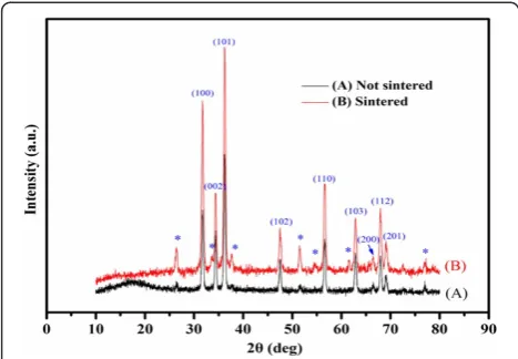
Figure 2 shows XRD patterns of the ZnO films before and after sintering. These two samples exhibited similar patterns except for differences in the peak intensity. Apart from those corresponding to the FTO substrate, the diffraction peaks can be indexed to the hexagonal
wurtzite ZnO (JCPDS card no. 79–0206). No other
[image:3.595.307.537.500.703.2]diffraction peaks were found in both cases, indicating that the prepared ZnO films are of the pure wurtzite phase, and no phase transformation occurs during thermal treatment. The diffraction peaks of the ZnO film became shaper after sintering, implying that the thermal treatment raised the crystallinity of the ZnO
film. Based on the XRD data, average crystallite size was estimated using the Scherrer's equation:
D¼B0:89λ
cosθ; ð1Þ
where 0.89 is the Debye-Scherrer's constant, λ is the
X-ray wavelength (0.15406 nm), θ is the Bragg's angle
(measured in radians) at which the peak is observed, and
Bis the full width at half maximum. The crystallite sizes before and after sintering, as estimated from major reflections, were both approximately 20 nm. The results show that sintering did not have a significant effect on crystallite size. The estimated crystallite size matched the size of the nanoparticles in the film.
Photovoltaic characteristics of fabricated DSSCs
The performance of the fabricated DSSCs was measured under 1 sun AM 1.5 G simulated light. Figure 3 shows the dependence of various photovoltaic parameters on the dye adsorption time and the film thickness:JSC,VOC, fill factor (FF), and overall conversion efficiency. Figure 3a shows a plot of JSC versus the dye adsorption time for various film thicknesses. Except for the thinnest
photoanode (14 μm), where the JSC values decrease
continuously with increasing dye adsorption time, the
JSC values of the remaining cells exhibit a similar trend with the dye adsorption time: theJSCvalues first increase as the dye adsorption time increases, reach a peak value, and then decrease as the dye adsorption time increases.
The initial rise in the JSC values with increasing dye
adsorption time is likely the result of increasing dye molecule adsorption on the ZnO film. However, when the dye adsorption time becomes too long, dye mole-cules can aggregate on the metal oxide surface, reducing
JSC [32,35-37]. Dye molecules exhibit slower electron
injection or self-quench if they undergo aggregation, which can occur either before or during dye adsorption on metal oxides [40]. Figure 3a also shows that different film thicknesses require different dye adsorption times
to achieve their respective peak JSC values. The dye
adsorption time required to achieve the maximum JSC
value increased from 1 h for the 20-μm photoelectrode
to approximately 3 h for the 31-μm photoelectrode. The 26-μm photoelectrode achieved the highestJSC.
Figure 3b presents a comparison of VOCvalues of the
fabricated devices. This figure shows that theVOCvalues first increase with the dye adsorption time. After
reach-ing a maximum VOC value, a further increase in the
adsorption time leads to a decline in the VOC value.
Similar to the JSC plot, the adsorption time required to
achieve the respective maximum VOC increases as the
film thickness increases. Figure 3b also shows that the
maximum VOC values decrease slightly as the film
thickness increases. This is likely the result of increased charge recombination and more restricted mass transfer with thick films. As the film thickness increases, electrons encounter a longer transport distance and recombine more easily with I3−. This results in a stronger electron transfer resistance and a shorter electron lifetime in the ZnO film [31]. The FF values shown in Figure 3c exhibit no clear trends. The FF values vary between 0.67 and 0.72, which are relatively high compared to those reported for ZnO-based DSSCs [37,41].
[image:4.595.56.290.89.251.2]Based on these parameters, the overall conversion efficiencies at various dye adsorption times and film thicknesses were calculated. The efficiency plot (Figure 3d) closely resembles theJSCplot (Figure 3a). Their trends are similar and their peak values appear at the same dye ad-sorption times.JSCis the efficiency-determining parameter because the dye adsorption time has a considerably stron-ger effect on JSC than on other photovoltaic parameters. Figure 3d also shows that each film thickness has a unique optimal dye adsorption time at which the maximum conversion efficiency occurs. The optimal dye adsorption time determined at a given film thickness does not apply to other thicknesses. This is because the dye adsorption time is either too short or too long for other film thicknesses, resulting in considerably lower efficiencies. For example, when a dye adsorption time of 3 h (optimal for the 31-μm film) was applied to the 20-μm film, the conver-sion efficiency dropped from the peak value of 4.95% to approximately 3.4%, representing a 31% drop. Prolonged dye adsorption times cause dye aggregation [32,35-38] and etching of the ZnO surface [39], both of which result in performance deterioration in ZnO-based DSSCs. Con-versely, TiO2-based DSSCs are typically less sensitive to prolonged sensitization times because of the higher chem-ical stability of TiO2[32-34]. For example, Lee et al. [33] reported similar dye loadings and conversion efficiencies
for TiO2/N719-based DSSCs when the dye soaking time was extended from 2 to 24 h. Table 1 presents a summary of the photovoltaic characteristics of the best-performing cell for each film thickness, along with the corresponding optimal dye adsorption time. The optimal dye adsorption time varies with the film thickness; thicker films require longer dye adsorption times. In addition, the attainable conversion efficiency depends on the photoanode thickness. A photoanode that is too thin or too thick results in a lower conversion efficiency. This is because insufficient film thick-ness leads to a low interfacial surface area, whereas an
overly thick film aggravates unwanted charge recombination and poses more restriction on mass transfer [14,21,30,31]. Consequently, for the fabrication of ZnO/N719-based DSSCs, the dye adsorption time must be optimized simul-taneously with the film thickness. A 26-μm-thick photoa-node soaked in the dye solution for 2 h achieved the highest conversion efficiency (5.61%) of all the cells prepared in this study. Figure 4 shows theJ-Vcurve of the best-performing cell measured under 1 sun AM 1.5 G simulated light.
[image:5.595.60.539.88.453.2]To better understand the effects of dye adsorption time on cell performance, this study also investigates dye
Figure 3Dependence of photovoltaic parameters of fabricated cells on dye adsorption time and ZnO film thickness.(a)JSC, (b)VOC, (c) FF, and (d) conversion efficiency.
Table 1 Optimal dye adsorption times and photovoltaic characteristics of best-performing cell at each film thickness
Film thickness (μm) Optimal dye adsorption time (h)
Conversion efficiency (%) Short-circuit photocurrent
density (mA/cm2) Open circuitvoltage (V) Fill factor
14 0.5 3.98 9.00 0.65 0.68
20 1 4.92 10.35 0.66 0.72
26 2 5.61 11.95 0.68 0.69
[image:5.595.55.540.656.734.2]loading in cells based on 26-μm-thick films. Figure 5
shows the correlation between JSC and dye loading as a
function of dye adsorption time. The amount of adsorbed dye molecules increases continuously as the adsorption time increases, whereas theJSCvalue reaches a maximum value and then decreases as the dye adsorp-tion time increases. This observaadsorp-tion is in contrast to that
reported for TiO2-based DSSCs, where dye loading
reached saturation after 2 h of sensitization and remained at the same level even when the sensitization time increased to 24 h [33]. The continuous increase of dye loading with sensitization time observed here suggests that the JSC deterioration is the result of dye aggregation. In this study, the ZnO film was sensitized with the weak acidic N719 dye, which was adsorbed onto the surface of ZnO particles through the carboxylic acid anchoring
group. Compared to TiO2, ZnO is less stable in acidic
dyes. Thus, immersing ZnO in an acidic dye solution for a long period can lead to ZnO dissolution and the formation of Zn2+/dye aggregates [32,35-37]. When dye aggregation
occurs, dye molecules exhibit slower electron injection and charge recombination aggravates, resulting in lower
JSCvalues [36,37].
[image:6.595.56.291.89.244.2]To determine parameters related to electron transport and recombination, this study used EIS to analyze cells based on 26-μm-thick films. The experimental impedance data, given by the Nyquist plots in Figure 6b, were fitted to an equivalent circuit based on the diffusion-recombination model [42-44] (Figure 6a). The circuit elements related to the ZnO photoelectrode include the electron transport re-sistance within the ZnO mesoporous film (Rw) (Rw=rwL, where L= film thickness), the charge transfer resistance (Rk) (Rk=rk/L), which is related to the recombination of electrons at the ZnO/electrolyte interface, and the chemical capacitance of the ZnO electrode (Cμ) (Cμ= cμL). Add-itional circuit elements were introduced to modify the equivalent circuit model, as described in the following. The series resistance (RS) represents total transport resistance of the FTO substrates and external circuits.ZNis the imped-ance of the diffusion of I3−in the electrolyte.RPtandCPtare the resistance and the capacitance at the Pt/electrolyte interface, respectively. RFTO and CFTO are the resistance and the capacitance at the FTO/electrolyte interface, respectively. RFZ and CFZ represent the resistance and the capacitance at the FTO/ZnO interface, respectively.
Figure 4J-Vcurve of the best-performing cell.The cell was prepared with a 26-μm film sensitized in a dye solution for 2 h.
[image:6.595.305.539.399.682.2]Figure 5Relationship betweenJSCand dye loading as a function of dye adsorption time.ZnO film thickness is 26μm.
[image:6.595.57.293.551.704.2]The three fitted parameters of Rw, Rk, and Cμ can be used to calculate additional parameters, such as the mean electron lifetime (τeff), effective electron diffusion coefficient (Deff), and effective electron diffusion length (Leff), which are useful for evaluating cell performance.
The Nyquist plots in Figure 6b show the experimental impedance data obtained at various dye adsorption times. The impedance spectra of DSSCs generally exhibit three semicircles. The semicircle in the high-frequency range corresponds to charge transfer behavior at the Pt/ electrolyte (RPtand CPt), the FTO/electrolyte (RFTOand CFTO), and the FTO/ZnO (RFZ and CFZ) interfaces. The semicircle in the mid-frequency range (the central arc) is assigned to the electron transfer at the ZnO/dye/electrolyte interfaces, which is related to Rw, Rk, and Cμ. The semi-circle in the low-frequency range represents the Warburg diffusion process of I−/I3−in the electrolyte (ZN) [42-45].
Table 2 presents a summary of results from fitting the experimental impedance data to the equivalent circuit. The highestRk/Rwvalue occurs at a dye adsorption time of 2 h, which is the optimal dye adsorption time for 26-μ
m-thick photoanodes. Both JSC and conversion efficiency
reach their maxima at this dye adsorption time (Figure 5). The highRk/Rwvalue obtained at the optimal dye adsorp-tion time suggests that a large number of electrons are injected into the photoelectrode [45,46]. The injected electrons undergo forward transport in the photoanode or recombine with I3−. This result explains the highJSCvalue observed at the optimal dye adsorption time. In addition, the keff value can be estimated from the characteristic frequency at the top of the central arc (keff=ωmax) of the impedance spectra. The parameterτeffwas then estimated as the reciprocal of keff (τeff= 1/keff) [45]. Table 2 shows thatτeffreaches its highest value at a dye adsorption time of 2 h. Lower τeff values result at insufficient (<2 h) or prolonged dye adsorption times (>2 h). The trend observed here is unlike that of TiO2-based cells, whose photovoltaic performance and corresponding EIS spectra remain unchanged after an adsorption time of 12 h [34]. The resistance reaches a constant level once sufficient dye molecules are adsorbed onto the TiO2surfaces, and does
not increase at prolonged adsorption times. When the dye adsorption time is insufficient, the ZnO surface is not completely covered with the dye molecules, and certain areas are in direct contact with the electrolyte. Conse-quently, severe charge recombinations lead to lowτeffand
VOC values. Prolonged dye adsorption times can lead to
ZnO dissolution and the formation of Zn2+/dye aggregates with acidic dyes [32,35-37], such as the N719 dye used in this study. Dye aggregation leads to slower electron injection and higher charge recombination [36,37]. The end result is a lowerJSCand overall conversion efficiency [39]. These reports support the trends ofτeffandJSCversus dye adsorption time observed in this study.
The effective electron diffusion time (τd) in the photoa-nodes is given by τd=τeff/(Rk/Rw). The lowest τd also occurs at the optimal dye adsorption time of 2 h, indicating that the optimal dye adsorption time enhanced electron transport in the ZnO photoanode. Charge collection efficiencies (ηCC) were estimated using the relationηCC= 1−τd/τeff [47]. Again,ηCCreaches its maximum value at the optimal dye adsorption time of 2 h, suggesting that using an appropriate dye adsorption time minimizes charge recombination.
[image:7.595.58.539.610.716.2]The parameterDeffwas then calculated using the relation Deff= (Rk/Rw)(L2/τeff), whereLis the thickness of the ZnO film (26μm). The highestDeff value (8.05 × 10⁻³cm2s−1) was also obtained at the optimal dye adsorption time of 2 h. This highDeffvalue can be explained by more injected electrons and induced faster transport of electrons. The parameter Leff, calculated by the relation Leff= (Deff×τeff)1/2, reflects the competition between the col-lection and recombination of electrons. A cell fabricated using the optimal dye adsorption time of 2 h achieved the highestLeffvalue of 111.6μm, which exceeds the thickness of the photoelectrode (26μm). This indicates that most of the injected electrons reached the FTO substrate before recombination occurred. ThisLefftrend shows good agree-ment with that ofJSC. Increased recombination can explain the significant drop in JSC values at other dye adsorption times. Overall, the EIS analysis results are in good agree-ment with the measured device performance parameters.
Table 2 Effects of dye adsorption time on electron transport properties of fabricated cells
Dye adsorption
time (h) Rk
/Rw Mean electron lifetime (ms)
Effective electron diffusion time (ms)
Charge collection efficiency (%)
Effective electron diffusion
coefficient (×10−3cm2s−1) diffusion length (Effective electronμm)
0.5 5.22 8.40 1.61 80.8 4.21 59.4
1 10.61 12.63 1.19 90.6 5.68 84.7
1.5 13.10 12.63 0.96 92.4 7.01 94.1
2 18.43 15.48 0.84 94.6 8.05 111.6
2.5 10.95 13.91 1.27 90.9 5.86 86.0
3 8.68 12.63 1.46 88.5 3.79 76.6
The thickness of the photoelectrode was 26μm.Rk, charge transfer resistance at the ZnO/electrolyte interface;Rw, electron transport resistance in the ZnO
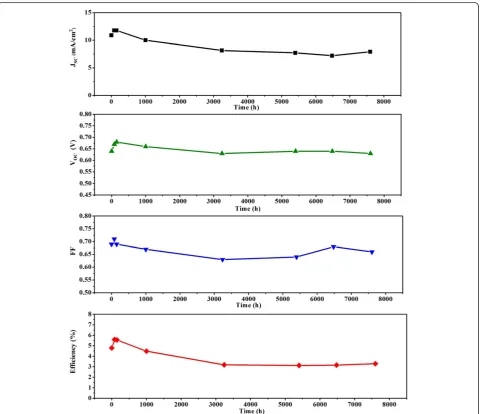
The DSSC prepared using the optimized fabrication
condition (film thickness = 26 μm and dye adsorption
time = 2 h) was also subjected to a long-term at-rest stability test, in which the cell was stored in the dark at room temperature. Figure 7 shows the changes in photo-voltaic characteristics over time. The efficiency data shown in this figure are the average of three measure-ments. During the first 100 h, the device performance improved slightly. The power conversion efficiency
increased from 4.76% to 5.61%, whereas JSC rose from
10.9 to 11.78 mA/cm2. From 100 to 3000 h, the overall
conversion efficiency gradually decreased to 3.39% because of the decline of JSC,VOC, and FF. Thereafter, the overall conversion efficiency remained nearly un-changed for 8,000 h, as did theJSC,VOC, and FF values. Although the fabricated cell used a liquid electrolyte, it
demonstrated excellent at-rest stability and retained approximately 70% of its initial efficiency after more than 1 year of storage.
Conclusions
[image:8.595.59.540.299.713.2]In summary, this study reports the successful fabrication of DSSC photoelectrodes using commercially available ZnO particles sensitized with acidic N719 dye. The effects of two fabrication factors, the film thickness and the dye adsorption time, were systematically investi-gated. The results show that to obtain efficient ZnO/ N719-based DSSCs, the dye adsorption time must be varied with the photoanode thickness. This is because the dye adsorption time suited for a particular film thickness does not apply to other film thicknesses. This is primarily because prolonged dye sensitization times
lead to significant deterioration in the performance of ZnO-based cells. This is in contrast to the typical behavior for TiO2-based cells, which usually adopt a single suffi-ciently long dye adsorption time for all film thicknesses. This is because TiO2-based cells are generally insensitive to prolonged sensitization times because of the higher chem-ical stability of TiO2. Through systematic optimization of the film thickness and the dye adsorption time, the highest overall conversion efficiency achieved in this study was 5.61%, obtained from a 26-μm photoelectrode sensitized for 2 h. The best-performing cell also showed remarkable at-rest stability, retaining approximately 70% of its initial efficiency after more than 1 year of room-temperature storage in the dark.
Abbreviations
AM: Air mass; DSSC: Dye-sensitized solar cells; EIS: Electrochemical impedance spectroscopy; FE-SEM: Field-emission scanning electron microscopy; FF: Fill factor; FTO: Fluorine-doped tin oxide;JSC: Short-circuit photocurrent density;VOC: Open circuit voltage; XRD: X-ray diffraction.
Competing interests
The authors declare that they have no competing interests.
Authors' contributions
WCC designed and performed the experiment, analyzed the data, and helped draft the manuscript. CML helped draft the manuscript. WCY conceived the study, participated in its design and coordination, and helped with the manuscript preparation. CHL helped draft the manuscript. All authors read and approved the final manuscript.
Acknowledgements
The authors acknowledge the financial support from the Bureau of Energy, Ministry of Economic Affairs, Taiwan (project no. B455DR2110) and National Science Council, Taiwan (project no. NSC 101-2221-E-027-120). The authors also thank Professor Chung-Wen Lan at the Department of Chemical Engineering, National Taiwan University for instrument support.
Author details 1
Institute of Organic and Polymeric Materials, National Taipei University of Technology, Taipei 10608, Taiwan.2Green Energy and Environment Research Laboratories, Industrial Technology Research Institute, Hsinchu 31053, Taiwan.
Received: 8 October 2012 Accepted: 12 December 2012 Published: 28 December 2012
References
1. Nazeeruddin MK, De Angelis F, Fantacci S, Selloni A, Viscardi G, Liska P, Ito S, Takeru B, Grätzel MG:Combined experimental and DFT-TDDFT
computational study of photoelectrochemical cell ruthenium sensitizers.
J Am Chem Soc2005,127:16835–16847.
2. Chen CY, Wang MK, Li JY, Pootrakulchote N, Alibabaei L, Ngoc-Le CH, Decoppet JD, Tsai JH, Grätzel C, Wu CG, Zakeeruddin SM, Grätzel M:Highly efficient light-harvesting ruthenium sensitizer for thin-film dye-sensitized solar cells.ACS Nano2009,3:3103–3109.
3. Hara K, Horiguchi T, Kinoshita T, Sayama K, Sugihara H, Arakawa H:Highly efficient photon-to-electron conversion with mercurochrome-sensitized nanoporous oxide semiconductor solar cells.Sol Energy Mater Sol Cells 2000,64:115–134.
4. Sayama K, Sugihara H, Arakawa H:Photoelectrochemical properties of a porous Nb2O5electrode sensitized by a ruthenium dye.Chem Mater
1998,10:3825–3832.
5. Katoh R, Furube A, Yoshihara T, Hara K, Fujihashi G, Takano S, Murata S, Arakawa H, Tachiya M:Efficiencies of electron injection from excited N3 into nanocrystalline semiconductor (ZrO2, TiO2, ZnO, Nb2O5, SnO2, In2O3) films.J Phys Chem B2004,108:4818–4822.
6. Quintana M, Edvinsson T, Hagfeldt A, Boschloo G:Comparison of dye-sensitized ZnO and TiO2solar cells: studies of charge transport and carrier lifetime.J Phys Chem C2007,111:1035–1041.
7. Gao YF, Nagai M, Chang TC, Shyue JJ:Solution-derived ZnO nanowire array film as photoelectrode in dye-sensitized solar cells.Cryst Growth Des2007,7:2467–2471.
8. Jiang CY, Sun XW, Lo GQ, Kwong DL, Wang JX:Improved dye-sensitized solar cells with a ZnO-nanoflower photoanode.Appl Phys Lett2007,
90(26):263501.
9. Hosono E, Fujihara S, Honna I, Zhou H:The fabrication of an upright-standing zinc oxide nanosheet for use in dye-sensitized solar cells.
Adv Mater2005,17:2091–2094.
10. Zhang Q, Dandeneau CS, Zhou X, Cao G:ZnO nanostructures for dye-sensitized solar cells.Adv Mater2009,21:4087–4108.
11. Zhang Q, Cao G:Nanostructured photoelectrodes for dye-sensitized solar cells.Nano Today2011,6:91–109.
12. Martinson ABF, Elam JW, Hupp JT, Pellin MJ:ZnO nanotube based dye-sensitized solar cells.Nano Lett2007,7:2183–2187.
13. Zhang Q, Myers D, Lan J, Jenekhe SA:Applications of light scattering in dye-sensitized solar cells.Phys Chem Chem Phys2012,14:14982–14998. 14. Wang ZS, Kawauchi H, Kashima T, Arakawa H:Significant influence of TiO2
photoelectrode morphology on the energy conversion efficiency of N719 dye-sensitized solar cell.Coord Chem Rev2004,248:1381–1389. 15. Kang SH, Kim JY, Kim HS, Koh HD, Lee JS, Sung YE:Influence of light
scattering particles in the TiO2photoelectrode for solid-state dye-sensitized solar cell.J Photochem Photobiol A2008,200:294–300. 16. Ito S, Nazeeruddin M, Liska P, Comte P, Charvet R, Péchy P, Jirousek M, Kay
A, Zakeeruddin S, Grätzel M:Photovoltaic characterization of dye-sensitized solar cells: effect of device masking on conversion efficiency.
Prog Photovolt Res Appl2006,14:589–601.
17. Hore S, Vetter C, Kern R, Smit H, Hinsch A:Influence of scattering layers on efficiency of dye-sensitized solar cells.Sol Energy Mater Sol Cells2006,
90:1176–1188.
18. Ito S, Nazeeruddin M, Zakeeruddin S, Péchy P, Comte P, Grätzel M, Mizuno T, Tanaka A, Koyanagi T:Study of dye-sensitized solar cells by scanning electron micrograph observation and thickness optimization of porous TiO2electrodes.Int J Photoenergy2009,2009:517609.
19. Ito S, Murakami T, Comte P, Liska P, Grätzel C, Nazeeruddin M, Grätzel M:
Fabrication of thin film dye sensitized solar cells with solar to electric power conversion efficiency over 10%.Thin Solid Films2008,516:4613–4619. 20. Qiu Y, Chen W, Yang S:Double-layered photoanodes from variable-size
anatase TiO2nanospindles: a candidate for high-efficiency dye-sensitized solar cells.Angew Chem Int Ed2010,49:3675–3679.
21. Tan B, Wu YY:Dye-sensitized solar cells based on anatase TiO2 nanoparticle/nanowire composites.J Phys Chem B2006,110:15932–15938. 22. Kevin M, Fou YH, Wong ASW, Ho GW:A novel maskless approach towards
aligned, density modulated and multi-junction ZnO nanowires for enhanced surface area and light trapping solar cells.Nanotechnology 2010,21:315602–315610.
23. Tetreault N, Horvath E, Moehl T, Brillet J, Smajda R, Bungener S, Cai N, Wang P, Zakeeruddin SM, Forro L, Magrez A, Grätzel M:High-efficiency solid-state dye-sensitized solar cells: fast charge extraction through self-assembled 3D fibrous network of crystalline TiO2nanowires.ACS Nano2010, 4:7644–7650.
24. Lin CJ, Yu WY, Chien SH:Effect of anodic TiO2powder as additive on electron transport properties in nanocrystalline TiO2dye-sensitized solar cells.Appl Phys Lett2007,91:233120.
25. Nakayama K, Kubo T, Nishikitani Y:Deposited TiO2nanotube light-scattering layers of electrophoretically dye-sensitized solar cells.
Jpn J Appl Phys2008,47:6610–6614.
26. Chou TP, Zhang QF, Fryxell GE, Cao GZ:Hierarchically structured ZnO film for dye-sensitized solar cells with enhanced energy conversion efficiency.Adv Mater2007,19:2588–2592.
27. Zhang Q, Chou TP, Russo B, Jenekhe SA, Cao G:Polydisperse aggregates of ZnO nanocrystallites: a method for energy-conversion-efficiency enhancement in dye-sensitized solar cells.Adv Funct Mater2008,
18:1654–1660.
29. Zhang Q, Park K, Xi J, Myers D, Cao G:Recent progress in dye-sensitized solar cells using nanocrystallite aggregates.Adv Energy Mater2011,
1:988–1001.
30. Lee B, Hwang DK, Guo P, Ho ST, Buchholtz DB, Wang CY, Chang RPH:
Materials, interfaces, and photon confinement in dye-sensitized solar cells.J Phys Chem B2010,114:14582–14591.
31. Hsu CP, Lee KM, Huang JTW, Lin CY, Lee CH, Wang LP, Tsai SY, Ho KC:EIS analysis on low temperature fabrication of TiO2porous films for dye-sensitized solar cells.Electrochim Acta2008,53:7514–7522.
32. Chou TP, Zhang QF, Cao GZ:Effects of dye loading conditions on the energy conversion efficiency of ZnO and TiO2dye-sensitized solar cells.
J Phys Chem C2007,111:18804–18811.
33. Lee KM, Suryanarayanan V, Huang JH, Justin Thomas KR, Lin JT, Ho KC:
Enhancing the performance of dye-sensitized solar cells based on an organic dye by incorporating TiO2nanotube in a TiO2nanoparticle film.
Electrochim Acta2009,54:4123–4130.
34. Kim JK, Seo H, Son MK, Shin I, Hong J, Kim HJ:The analysis of the change in the performance and impedance of dye-sensitized solar cell according to the dye-adsorption time.Curr Appl Phys2010,10:S418–S421. 35. Horiuchi H, Katoh R, Hara K, Yanagida M, Murata S, Arakawa H, Tachiya M:
Electron injection efficiency from excited N3 into nanocrystalline ZnO films: effect of (N3-Zn2+) aggregate formation.J Phys Chem B2003,
107:2570–2574.
36. Keis K, Lindgren J, Lindquist SE, Hagfeldt A:Studies of the adsorption process of Ru complexes in nanoporous ZnO electrodes.Langmuir2000,
16:4688–4694.
37. Qin Z, Huang YH, Qi JJ, Qu L, Zhang Y:Improvement of the performance and stability of the ZnO nanoparticulate film electrode by surface modification for dye-sensitized solar cells.Colloids Surf A2011,386:179–184.
38. Sakuragi Y, Wang XF, Miura H, Matsui M, Yoshida T:Aggregation of indoline dyes as sensitizers for ZnO solar cells.J Photochem Photobiol A 2010,216:1–7.
39. Yan FP, Huang LH, Zheng JS, Huang J, Lin Z, Huang F, Wei MD:Effect of surface etching on the efficiency of ZnO-based dye-sensitized solar cells.
Langmuir2010,26:7153–7156.
40. Thavasi V, Renugopalakrishnan V, Jose R, Ramakrishna S:Controlled electron injection and transport at materials interfaces in dye sensitized solar cells.Mater Sci Eng R2009,63:81–99.
41. Saito M, Fujihara S:Large photocurrent generation in dye-sensitized ZnO solar cells.Energy Environ Sci2008,1:280–283.
42. Juan B:Theory of the impedance of electron diffusion and recombination in a thin layer.J Phys Chem B2002,106:325–333. 43. Wang KP, Teng H:Zinc-doping in TiO2films to enhance electron
transport in dye-sensitized solar cells under low-intensity illumination.
Phys Chem Chem Phys2009,11:9489–9496.
44. Chang WC, Cheng YY, Yu WC, Yao YC, Lee CH, Ko HH:Enhancing performance of ZnO dye-sensitized solar cells by incorporation of multiwalled carbon nanotubes.Nanoscale Res Lett2012,7:166–172. 45. Adachi M, Sakamoto M, Jiu J, Ogata Y, Isoda S:Determination of
parameters of electron transport in dye-sensitized solar cells using electrochemical impedance spectroscopy.J Phys Chem B2006,
110:13872–13880.
46. Lee CH, Chiu WH, Lee KM, Yen WH, Lin HF, Hsieh WF, Wu JM:The influence of tetrapod-like ZnO morphology and electrolytes on energy conversion efficiency of dye-sensitized solar cells.Electrochim Acta2010,55:8422–8429. 47. Wang Q, Zhang Z, Zakeeruddin SM, Grätzel M:Enhancement of the
performance of dye-sensitized solar cell by formation of shallow transport levels under visible light illumination.J Phys Chem C2008,
112:7084–7092.
doi:10.1186/1556-276X-7-688
Cite this article as:Changet al.:Optimization of dye adsorption time and film thickness for efficient ZnO dye-sensitized solar cells with high at-rest stability.Nanoscale Research Letters20127:688.
Submit your manuscript to a
journal and benefi t from:
7Convenient online submission 7Rigorous peer review
7Immediate publication on acceptance 7Open access: articles freely available online 7High visibility within the fi eld
7Retaining the copyright to your article